MEDEE: A METHOD FRAMEWORK FOR
MULTIAGENT SYSTEMS
Tese apresentada à Escola Politécnica da Universidade de São Paulo para a obtenção do Título de Doutor em Ciências
MEDEE: A METHOD FRAMEWORK FOR
MULTIAGENT SYSTEMS
Tese apresentada à Escola Politécnica da Universidade de São Paulo para a obtenção do Título de Doutor em Ciências
Área de Concentração: Sistemas Digitais
Orientador:
Prof. Dr. Jaime Simão Sichman
Este exemplar foi revisado e alterado em relação à versão original, sob responsabilidade única do autor e com a anuência de seu orientador.
São Paulo, 27 de janeiro de 2012.
Assinatura do autor ____________________________
Assinatura do orientador _______________________
FICHA CATALOGRÁFICA
Casare, Sara Jane
Medee: a method framework for the multiagent systems / S.J. Casare. -- ed.rev. -- São Paulo, 2012.
285 p.
Tese (Doutorado) - Escola Politécnica da Universidade de São Paulo. Departamento de Engenharia de Computação e Sis-temas Digitais.
A os m eus pais, W arner e D elurdes
Acknowledgements
It’s with great pleasure that I thank the all the people who made this thesis possible.
For Professor Jaime Sichman, for his careful and thorough guidance. In addition, I thank Jaime for his friendship during my eight years of research at the Laboratório de Tecnicas Inteligentes (LTI).
Professor Zahia Guessoum, for the welcome I received at the Laboratoire d'informatique de Paris 6 (LIP6) and for her guidance during the research period I undertook at the lab.
Anarosa Brandão for friendship and support in this important piece of work, especially during the preparation and execution of the case study.
Professors Selma Melnikoff, Viviane Torres da Silva, Jomi Fred Hübner, and Jeferson Soares for having accepted to be members of my jury and for having honored me with their presence Also, Professor Carlos Lucena for his valuable comments and suggestions on my qualifying exam. I am privileged and thankful for their careful reading and thoughtful comments.
For the staff and fellow researchers at LIP6. A special thanks to Amel Boustil, Javier Gil-Quijanoand Hélène Giroire.
To my colleagues at LTI, especially Gustavo Pacianotto for his support in conducting the case study.
To my managers at IBM, Antonio Froes and Eduardo Villela, who made it possible for me to take a year out to study.
CAPES, FAPESP and the Post Graduate Program in Electrical Engineering from the Polytechnic School at USP, for financial support.
FIGURE 1.1CURRENT DEVELOPMENT SCENARIO FOR ORGANIZATION CENTERED MAS ... 4
FIGURE 1.2THREE DEVELOPMENT SCENARIOS FOR ORGANIZATION CENTERED MAS: FROM CURRENT TO TARGET. 6 FIGURE 1.3:RESEARCH OBJECTIVES IN A DIAGRAMMATICAL PERSPECTIVE... 9
FIGURE 1.4:MAIN COMPONENTS OF THE RESEARCH APPROACH... 11
FIGURE 1.5:DISSERTATION STRUCTURE... 12
FIGURE 2.1: FOUR SOFTWARE ENGINEERING LAYERS (PRESSMAN,2010, P.14)... 16
FIGURE 2.2: THE PROCESS IMPROVEMENT CYCLE (SOMMERVILLE,2007)... 19
FIGURE 2.3: QIP SIX STEPS... 21
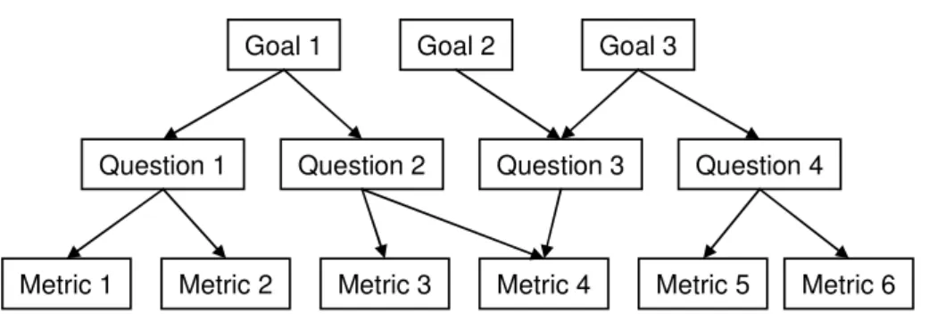
FIGURE 2.4: AN ABSTRACT GQM STRUCTURE COMPOSED OF GOALS, QUESTIONS AND METRIC (BASILI,1992) .. 25
FIGURE 2.5:RUP BI-DIMENSIONAL REPRESENTATION (KRUCHTEN,2003)... 31
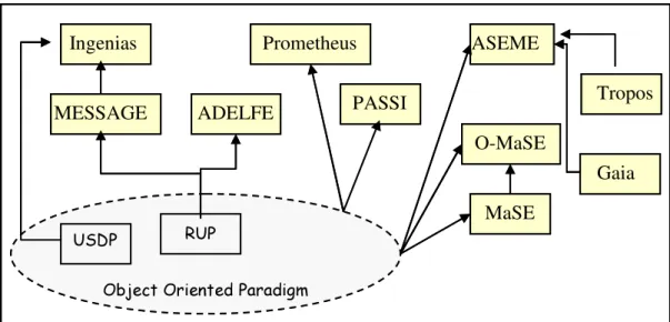
FIGURE 3.1: AOSE METHODS AND THEIR RELATIONSHIP WITH OBJECT-ORIENTED PARADIGM, INSPIRED BY (GIORGINI;HENDERSON-SELLERS,2005)... 49
FIGURE 4.1:AN ITERATIVE PROCEDURE FOR BUILDING SITUATIONAL METHODS, INSPIRED BY HARMSEN (1997) .. 60
FIGURE 4.2:S3 MODEL (HARMSEN,1997) ... 63
FIGURE 4.3:METHOD COMPONENT MAIN ELEMENTS... 66
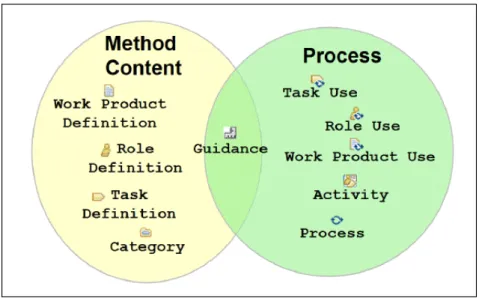
FIGURE 4.4:SPEM CORE CONCEPTS AND THEIR RELATIONSHIPS (HAUMER,2007A)... 69
FIGURE 4.5:SPEM KEY CONCEPTS MAPPED TO METHOD CONTENT AND PROCESS (OMG,2008A, P.14)... 69
FIGURE 4.6:SPEM CONCEPTUAL USAGE FRAMEWORK INSPIRED BY (OMG,2008A, P.10)... 73
FIGURE 4.7:EPFCOMPOSER ARCHITECTURE, INSPIRED ON (OMG,2008A) ... 75
FIGURE 4.8:AN EXAMPLE OF AN ACTIVITY DIAGRAM... 76
FIGURE 4.9:AN EXAMPLE OF AN ACTIVITY DETAILED DIAGRAM... 76
FIGURE 4.10:THE SEMIOTIC LADDER (STAMPER,1996)... 78
FIGURE 5.1: ELABORATING METHOD FRAGMENTS AND COMPOSING SITUATIONAL METHODS USING THE MEDEE METHOD FRAMEWORK, INSPIRED BY RALYTÉ (2001)... 87
FIGURE 5.2:THE MAIN ELEMENTS OF MEDEE MASSITUATIONAL METHOD AND MEDEE MASMETHOD FRAGMENT... 89
FIGURE 5.3:FROM THE MAS PROJECT SITUATION TO THE APPROPRIATE SITUATIONAL METHOD USING THE MEDEE COMPOSITION MODEL... 93
FIGURE 5.4PEOPLE FACTORS OF THE MEDEE PROJECT FACTORS TAXONOMY... 95
FIGURE 5.5:PROBLEM FACTORS OF THE MEDEE PROJECT FACTORS TAXONOMY... 96
FIGURE 5.6:PRODUCT FACTORS OF THE MEDEE PROJECT FACTORS TAXONOMY... 97
FIGURE 5.7:RESOURCE FACTORS OF THE MEDEE PROJECT FACTORS TAXONOMY... 98
FIGURE 5.13:EMPIRICAL LEVEL OF THE MEDEE MASSEMIOTIC TAXONOMY... 104
FIGURE 5.14:INSTABLE REQUIREMENTS GUIDELINE... 106
FIGURE 5.15:MAIN CONCEPTS OF THE MEDEE METHOD FRAMEWORK DEPICTED THROUGH A UML CLASS DIAGRAM... 109
FIGURE 5.16:THE MEDEE MASWORK PRODUCT FRAMEWORK DEPICTED THROUGH A UML CLASS DIAGRAM.. 110
FIGURE 5.17:THE MASACTIVITY METHOD FRAGMENT DEPICTED THROUGH A UML CLASS DIAGRAM... 112
FIGURE 5.18:THE MASITERATION METHOD FRAGMENT DEPICTED THROUGH A UML CLASS DIAGRAM... 113
FIGURE 5.19:THE MASPHASE METHOD FRAGMENT DEPICTED THROUGH A UML CLASS DIAGRAM... 115
FIGURE 5.20:THE MASPROCESS METHOD FRAGMENT DEPICTED THROUGH A UML CLASS DIAGRAM... 116
FIGURE 5.21:THE MEDEE MASSITUATIONAL METHOD DEPICTED THROUGH A UML CLASS DIAGRAM... 117
FIGURE 5.22:THE MEDEE COMPOSITION MODEL DEPICTED THROUGH A UML CLASS DIAGRAM... 118
FIGURE 6.1:MAIN COMPONENTS OF THE MEDEE FRAMEWORK... 122
FIGURE 6.2:THREE PILLARS OF THE MEDEE METHOD REPOSITORY... 124
FIGURE 6.3:THE MEDEE METHOD REPOSITORY DEPICTED THROUGH A UML CLASS DIAGRAM... 126
FIGURE 6.4:THE MEDEE ELEMENTS PILLAR DEPICTED THROUGH A UML CLASS DIAGRAM... 127
FIGURE 6.5:THE MEDEE FRAGMENT PILLAR DEPICTED THROUGH A UML CLASS DIAGRAM... 129
FIGURE 6.6:MEDEE MASSEMIOTIC TAXONOMY, DESCRIBING THE VALIDATION DEGREE CATEGORY... 130
FIGURE 6.7:MEDEE COMMON ROLES, DESCRIBING THE MASDESIGNER ROLE... 131
FIGURE 6.8:MEDEE WORK PRODUCT SLOTS, DESCRIBING THE MPSORGANIZATION ANALYSIS... 133
FIGURE 6.9:MASWORK PRODUCT VARIABILITY FOR EXTENDING TROPOS... 135
FIGURE 6.10:MASWORK PRODUCT VARIABILITY FOR EXTENDING MOISE+ ... 135
FIGURE 6.11:MASTASK VARIABILITY FOR EXTENDING MOISE+... 136
FIGURE 6.12:MTVANALYZE MASORGANIZATION, AFTER THE FULFILLMENT OF INPUT WORK PRODUCTS... 136
FIGURE 6.13:THE MEDEE METHODS PILLAR DEPICTED THROUGH A UML CLASS DIAGRAM... 137
FIGURE 6.14:SOME TERM DEFINITIONS OF THE MEDEE GLOSSARY... 138
FIGURE 6.15:THE THREE ELEMENTS OF THE MEDEE COMPOSITION MODEL AND THEIR RELATIONSHIPS... 139
FIGURE 6.16:MEDEE DELIVERY PROCESS ACTIVITY DIAGRAM... 140
FIGURE 6.17:METHOD ELEMENT CAPTURE PHASE REPRESENTED AS AN ACTIVITY DIAGRAM... 141
FIGURE 6.18:CAPTURE METHOD CONTENT ACTIVITY DETAILED DIAGRAM... 142
FIGURE 6.19:BUILD AOSE METHOD AS IS ACTIVITY DETAILED DIAGRAM... 144
FIGURE 6.20:PUBLISHED AOSE METHOD AS IS ACTIVITY DETAILED DIAGRAM... 145
FIGURE 6.21:METHOD FRAGMENT ELABORATION PHASE ACTIVITY DIAGRAM... 146
FIGURE 6.22:CREATE ACTIVITY METHOD FRAGMENT ACTIVITY DETAILED DIAGRAM... 147
FIGURE 6.23:CREATE INTERMEDIATE METHOD FRAGMENT ACTIVITY DETAILED DIAGRAM... 149
FIGURE 6.24:CREATE PROCESS METHOD FRAGMENT ACTIVITY DETAILED DIAGRAM... 150
FIGURE 6.25:MEDEE METHOD COMPOSITION PHASE ACTIVITY DIAGRAM... 151
FIGURE 6.30:GENERATE MEDEE AOSE METHOD ACTIVITY DETAILED DIAGRAM... 157
FIGURE 6.31:THE SEVEN STEPS OF THE MEDEE IMPROVEMENT CYCLE... 160
FIGURE 6.32: BIG PICTURE OF THE MEDEE IMPROVEMENT CYCLE, INSPIRED BY SOMMERVILLE (2007)... 165
FIGURE 7.1:ELABORATING METHOD FRAGMENTS USING THE MEDEE METHOD FRAMEWORK... 170
FIGURE 7.2:GAIA MODELS AND THEIR RELATIONSHIPS WITH THE DEVELOPMENT PHASES (ZAMBONELLI; JENNINGS;WOOLDRIDGE,2003) ... 171
FIGURE 7.3:TASKS AND WORK PRODUCTS CAPTURED FROM GAIA, DETAILING THE DEFINE AGENT MODEL TASK. ... 174
FIGURE 7.4:GUIDANCE CAPTURED FROM GAIA, DETAILING THE AGENT CONCEPT... 175
FIGURE 7.5:GAIA AS IS PUBLISHED BY EPFCOMPOSER... 175
FIGURE 7.6:MASWORK PRODUCT VARIABILITY FOR GAIA, DETAILING THE MPVGAIA AGENT DESIGN MODEL... 177
FIGURE 7.7:MASTASK VARIABILITY FOR GAIA, DETAILING THE MTVDEFINE AGENT MODEL... 177
FIGURE 7.8: MAS ACTIVITY METHOD FRAGMENTS SOURCED FROM GAIA, DETAILING MMFDESIGN AGENT WITH GAIA ... 179
FIGURE 7.9:MAS PHASE METHOD FRAGMENTS SOURCED FROM GAIA, DETAILING THE MMFDESIGN PHASE WITH GAIA ... 180
FIGURE 7.10:MILESTONE OF THE MMFDESIGN PHASE WITH GAIA... 180
FIGURE 7.11:MAS PROCESS METHOD FRAGMENTS SOURCED FROM GAIA, DETAILING THE MMFGAIA BASE METHOD ... 181
FIGURE 7.12:TROPOS PHASES AND WORK PRODUCTS... 183
FIGURE 7.13: TASKS AND WORK PRODUCTS CAPTURED FROM TROPOS, DETAILING THE IDENTIFY STAKEHOLDERS TASK... 185
FIGURE 7.14:GUIDANCE CAPTURED FROM TROPOS, DETAILING THE ACTOR MODELING GUIDELINE... 186
FIGURE 7.15:TROPOS AS IS PUBLISHED BY THE EPFCOMPOSER... 187
FIGURE 7.16:MAS WORK PRODUCT VARIABILITY FOR TROPOS, DETAILING THE MPVTROPOS ACTOR DIAGRAM... 189
FIGURE 7.17:MASTASK VARIABILITY FOR TROPOS, DETAILING MTVIDENTIFY STAKEHOLDERS... 189
FIGURE 7.18:MAS ACTIVITY METHOD FRAGMENTS SOURCED FROM TROPOS, DETAILING THE MMFIDENTIFY INITIAL REQUIREMENTS WITH TROPOS... 190
FIGURE 7.19:MAS PHASE METHOD FRAGMENTS SOURCED FROM TROPOS, DETAILING THE MMFREQUIREMENTS PHASE WITH TROPOS... 191
FIGURE 7.20:MASMETHOD FRAGMENTS SOURCED FROM TROPOS, ORGANIZED IN THE MMFTROPOS BASE METHOD ... 192
FIGURE 7.21MOISE+STRUCTURAL SPECIFICATION FOR A SOCCER TEAM (HUBNER;SICHMAN;BOISSIER, 2002,2007) ... 194
INFRASTRUCTURE FOR JASON... 199
FIGURE 7.25:MAS WORK PRODUCT VARIABILITY FOR MOISE+, DETAILING THE MPVORGANIZATIONAL SPECIFICATION ... 200
FIGURE 7.26:MAS TASK VARIABILITY FOR MOISE+, DETAILING THE MTVANALYZE MASORGANIZATION... 201
FIGURE 7.27:MASACTIVITY METHOD FRAGMENTS SOURCED FROM MOISE+, DETAILING THE MMFANALYZE ORGANIZATION WITH MOISE+... 202
FIGURE 7.28:TASKS AND WORK PRODUCTS CAPTURED FROM USDP, DETAILING FIND ACTORS AND USE CASES TASK... 204
FIGURE 7.29:MAS ACTIVITY METHOD FRAGMENTS SOURCED FROM USDP, DETAILING THE MMFIDENTIFY REQUIREMENTS WITH USDP... 205
FIGURE 8.1:MASENVIRONMENT COMPOSED BY COWBOYS (RED AND BLUE TRIANGLES), FENCES (GREEN OVALS), COWS (WHITE OVALS), AND OBSTACLES (BEHRENS ET AL.,2009) ... 212
FIGURE 8.2:APPLYING THE MEDEE IMPROVEMENT CYCLE TO THE USPFARMER PROJECT... 214
FIGURE 8.3:GQM MODEL FOR USPFARMER PROJECT, INSPIRED BY (BASILI;CALDIERA;ROMBACH,1994) ... 220
FIGURE 8.4:TOP-DOWN SITUATIONAL COMPOSITION, DETAILING SITUATIONAL PHASES USING TROPOS AND MOISE+... 229
FIGURE 8.5:TROPOS-MOISE SITUATIONAL METHOD PUBLISHED AS WEB PAGES... 230
FIGURE 8.6:BOTTOM-UP SITUATIONAL COMPOSITION, DETAILING SITUATIONAL PHASES USING GAIA,MOISE, USDP ... 231
FIGURE 8.7:GAIA-MOISE SITUATIONAL METHOD PUBLISHED AS WEB PAGES... 232
FIGURE 8.8:A PARTIAL VIEW OF QUESTIONNAIRE A–DEVELOPER VIEWPOINT... 234
FIGURE 8.9:THE MOISE+ ESTIMATION CONSIDERATION, DETAILING ITS IMPLEMENTATION ESTIMATION... 244
FIGURE 8.10:THE IMPROVED MMFIMPLEMENT AGENT WITH MOISE+... 245
FIGURE 8.11:THE IMPROVED MEDEE COMPOSITION MODEL... 245
FIGURE 8.12:IMPROVING MEDEE MAS METHOD FRAGMENTS SOURCED FROM TROPOS AND MOISE+... 246
FIGURE 8.13:IMPROVING MEDEE MAS METHOD FRAGMENTS SOURCED FROM GAIA AND USDP ... 247
FIGURE 8.14:IMPROVING MEDEE SITUATIONAL METHODS CLASSIFICATION... 247
FIGURE 10.1:PASSI DEVELOPMENT PHASES (COSSENTINO,2005)... 271
FIGURE 10.2:MAS METHOD FRAGMENTS SOURCED FROM PASSI, DETAILING THE MMFPASSIBASE METHOD USING USDP... 272
FIGURE 10.3:METHOD FRAGMENTS SOURCED FROM INGENIAS, DETAILING THE MMFENHANCED ELABORATION PHASE WITH INGENIAS... 274
FIGURE 10.4:OPERA ARCHITECTURE (DIGNUM,2004) ... 276
FIGURE 10.5:MASTASK VARIABILITY AND ACTIVITY METHOD FRAGMENTS SOURCED FROM OPERA... 277
FIGURE 11.1:FIRST PAGE OF QUESTIONNAIRE C–DEVELOPER VIEWPOINT... 279
FIGURE 12.1:MEDEE METHOD FRAGMENTS FOLDER AND THE FIREFOX INDEX FILE... 283
FIGURE 12.2:BROWSING MEDEE MAS METHOD FRAGMENTS... 283
FIGURE 12.3:BROWSING THE MEDEE SITUATIONAL METHOD CREATED DURING USPFARMER PROJECT... 284
FIGURE 12.4:BROWSING THE AOSE METHODS AS IS... 285
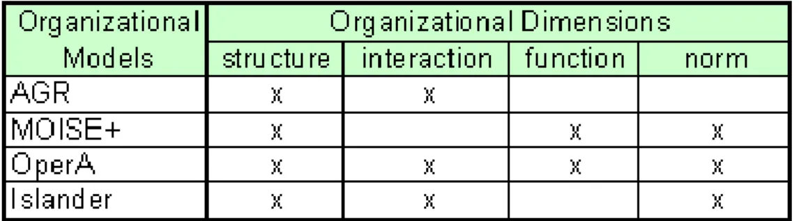
TABLE 3.1:AGENT ORGANIZATIONAL MODELS SUMMARY... 46
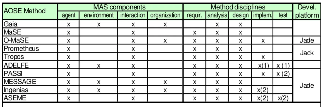
TABLE 3.2:AOSE METHODS SUMMARY... 55
TABLE 5.1:THE MEDEE COMPOSITION GUIDELINES... 107
TABLE 7.1:MEDEE METHOD REPOSITORY POPULATION SUMMARY... 207
TABLE 8.1:USPFARMER PROJECT SITUATION -PEOPLE FACTORS... 215
TABLE 8.2:USPFARMER PROJECT FACTORS ASSESSMENT USING MEDEE COMPOSITION MODEL... 225
TABLE 8.3:THE SIX QUESTIONNAIRES FOR COLLECTING GQM METRICS... 234
TABLE 8.4:COLLECTED GQM METRICS FROM A DEVELOPER’S VIEWPOINT... 237
TABLE 8.5:COLLECTED GQM METRICS FROM A PROJECT MANAGER’S VIEWPOINT... 239
TABLE 8.6:LESSONS LEARNED AND .IMPROVEMENT OPPORTUNITIES - MEASUREMENT GOALS 1 TO 4 ... 241
ADELFE Atelier de Développement de Logiciels à Fonctionnalité Emergente AOSE Agent-oriented Software Engineering
AUML Agent Unified Model Language
CASE Computer-Aided Software Engineering EPF Eclipse Process Framework
JADE Java Agent Development Framework
MAS Multiagent System
MOISE+ Model of Organization for Multiagent Systems MMF Medee MAS Method Fragment
MPS Medee work Product Slot MPV Medee work Product Variability MTV Medee Task Variability
OMG Object Management Group
PASSI Process for Agent Societies Specification and Implementation OperA Organization Per Agent
SPEM Software & Systems Process Engineering Meta-Model Specification RUP Rational Unified Process
UML Unified Model Language
CHAPTER 1 INTRODUCTION... 1
1.1MOTIVATION... 1
1.1.1 Multiagent Systems Development ... 2
1.1.2 Quality Focus in MAS Development... 5
1.2RESEARCH QUESTIONS... 7
1.3RESEARCH APPROACH... 7
1.3.1 Situational Method Engineering... 8
1.3.2 Research Objective ... 8
1.3.3 Research Procedure... 10
1.4TEXT STRUCTURE... 12
PART I BACKGROUND AND RELATED WORK ... 14
CHAPTER 2 SOFTWARE ENGINEERING... 15
2.1INTRODUCTION... 15
2.2SOFTWARE QUALITY FOCUS... 18
2.2.1 Overview... 18
2.2.2 Quality Improvement Paradigm ... 21
2.2.3 Goal Question Metric Paradigm ... 24
2.3SOFTWARE DEVELOPMENT METHOD... 26
2.3.1 Main notions... 26
2.3.2 Methods Overview ... 28
2.3.3 Unified Software Development Process (USDP)... 29
2.3.4 Rational Unified Process (RUP)... 30
2.3.5 Method Quality Attributes ... 32
2.4DISCUSSION... 33
CHAPTER 3 MULTIAGENT SYSTEMS DEVELOPMENT ... 36
3.1 INTRODUCTION... 36
3.2 THE AGENT-ORIENTED PARADIGM... 38
3.2.1 Vowel: Agent, Environment, Interaction, Organization ... 38
3.2.2 Agent Architectures ... 39
3.2.3 Agent Applications... 40
3.3.3 MOISE+ ... 44
3.3.4 OperA ... 45
3.3.5 Islander... 45
3.3.6 Agent Organizational Models Summary... 46
3.4AGENT-ORIENTED SOFTWARE ENGINEERING... 47
3.4.1 Overview... 47
3.4.2 Gaia ... 49
3.4.3 MaSE and O-MaSE... 50
3.4.4 Prometheus ... 51
3.4.5 Tropos... 51
3.4.6 ADELFE ... 52
3.4.7 PASSI... 52
3.4.8 Ingenias and MESSAGE ... 53
3.4.9 ASEME ... 54
3.4.10 AOSE Methods Summary... 54
3.5DISCUSSION... 56
CHAPTER 4 SITUATIONAL METHOD ENGINEERING... 58
4.1INTRODUCTION... 58
4.2MAIN APPROACHES... 60
4.2.1 Method Fragment ... 61
4.2.2 Method Chunk... 63
4.2.3 Work Product Description... 64
4.2.4 Method Component... 65
4.3META-MODELS,FRAMEWORKS, AND TOOLS... 67
4.3.1 Overview... 67
4.3.2 Software and System Process Engineering Meta-model (SPEM)... 68
4.3.3 Eclipse Process Framework Composer ... 74
4.3.4 Semiotic Ladder... 77
4.4SITUATIONAL METHOD ENGINEERING FOR MAS ... 78
4.4.1 Overview... 78
4.4.2 FIPA’s Approach... 79
4.4.3 Cossentino et al. Approach... 81
4.4.4 Henderson-Sellers et al. Approach... 82
5.1INTRODUCTION... 85
5.2 MEDEE MASMETHOD FRAGMENT AND MEDEE MASSITUATIONAL METHOD... 87
5.2.1 Definition... 87
5.2.2 Main Elements ... 89
5.2.3 Medee MAS Method Fragment Layers ... 90
5.2.4 Medee MAS Work Product Framework... 91
5.2.5 Medee MAS Internal and External Views... 91
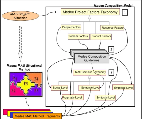
5.3MEDEE COMPOSITION MODEL... 92
5.3.1 Overview... 92
5.3.2 Medee Project Factors Taxonomy... 94
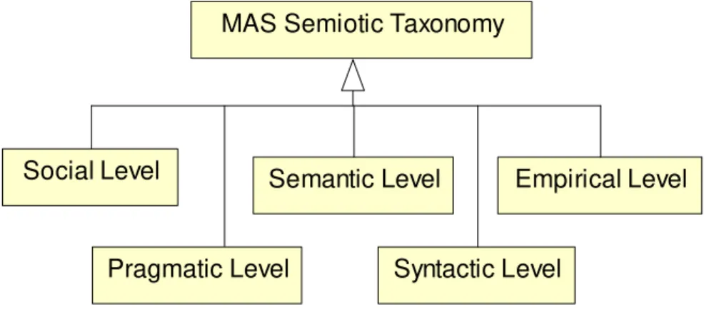
5.3.3 Medee MAS Semiotic Taxonomy... 99
5.3.4 Medee Composition Guidelines ... 105
5.4MEDEE CONCEPTUAL MODEL... 107
5.4.1 Overview... 108
5.4.2 MAS Work Product Framework ... 109
5.4.3 MAS Activity Method Fragment ... 111
5.4.4 MAS Iteration Method Fragment... 113
5.4.5 MAS Phase Method Fragment... 114
5.4.6 MAS Process Method Fragment and MAS Base Method ... 115
5.4.7 MAS Situational Method... 117
5.4.8 Medee Composition Model ... 118
5.5CONCLUSIONS... 119
CHAPTER 6 THE MEDEE FRAMEWORK... 121
6.1INTRODUCTION... 121
6.2MEDEE METHOD REPOSITORY... 123
6.2.1 Architecture ... 123
6.2.2 Medee Elements Pillar... 127
6.2.3 Medee Fragments Pillar ... 128
6.2.4 Medee Methods Pillar... 137
6.3MEDEE DELIVERY PROCESS... 139
6.3.1 Overview... 140
6.3.2 Method Element Capture Phase ... 141
6.3.3 Method Fragment Elaboration Phase ... 145
6.3.4 Medee Method Composition Phase ... 150
6.4 MEDEE IMPROVEMENT CYCLE... 157
6.4.1 Overview... 158
6.4.6 Executing MAS Project and Collecting Metrics ... 163
6.4.7 Analyzing MAS Project Execution... 164
6.4.8 Packaging MAS Project Experience... 164
6.4.9 Summing up with an Iterative Perspective... 165
6.5CONCLUSIONS... 166
PART III APPLICATION OF THE MEDEE FRAMEWORK ... 168
CHAPTER 7 POPULATING THE MEDEE METHOD REPOSITORY ... 169
7.1INTRODUCTION... 169
7.2GAIA AS MEDEE SOURCE... 171
7.2.1 Gaia in a Nutshell... 171
7.2.2 Capturing Method Elements from Gaia... 173
7.2.3 Elaborating MAS Method Fragments Sourced from Gaia ... 176
7.2.4 Summing up Gaia as a Medee Source ... 182
7.3TROPOS AS MEDEE SOURCE... 182
7.3.1 Tropos in a Nutshell ... 182
7.3.2 Capturing Method Elements from Tropos ... 185
7.3.3 Elaborating MAS Method Fragments Sourced from Tropos ... 188
7.3.4 Summing up Tropos as a Medee Source... 193
7.4MOISE+ AS MEDEE SOURCE... 193
7.4.1 MOISE+ in a Nutshell ... 193
7.4.2 Capturing Method Elements from MOISE+ ... 197
7.4.3 Elaborating MAS Method Fragment Sourced from MOISE+ ... 200
7.4.4 Summing up MOISE+ as a Medee Source... 202
7.5UNIFIED SOFTWARE DEVELOPMENT PROCESS AS MEDEE SOURCE... 203
7.5.1 Introduction ... 203
7.5.2 Capturing Method Elements from USDP ... 204
7.5.3 Elaborating MAS Method Fragment sourced from USDP ... 205
7.5.4 Summing up USDP as a Medee Source ... 206
7.6CONCLUSIONS... 206
CHAPTER 8 USP FARMER PROJECT CASE STUDY... 209
8.1INTRODUCTION... 209
8.1.1 Overview... 209
8.1.2 Multiagent Programming Contest ... 211
8.1.3 Applying the Medee Improvement Cycle to the USP Farmer Project ... 213
8.2.5 USP Farmer Project Factors Summary... 218
8.3SETTING USPFARMER PROJECT GQMMODEL... 219
8.3.1 Overview... 219
8.3.2 GQM Model for USP Farmer Project ... 221
8.4 COMPOSING THE USPFARMER PROJECT SITUATIONAL METHODS... 223
8.4.1 Select MAS Method Fragments... 223
8.4.2 Compose and Publish Tropos-MOISE Situational Method (Top-down) ... 228
8.4.3 Compose and Publish Gaia-MOISE Situational Method (Bottom-up) ... 230
8.5EXECUTING THE USPFARMER PROJECT AND COLLECTING METRICS... 233
8.5.1 Design Questionnaire for Collecting Metrics... 233
8.5.2 Execute USP Farmer Project ... 235
8.5.3 Collect and Validate Metrics ... 236
8.6ANALYZING THE USPFARMER PROJECT... 236
8.6.1 Developer Viewpoint Goal Analysis ... 236
8.6.2 Project Manager Viewpoint Goal Analysis ... 239
8.7PACKAGING THE USPFARMER PROJECT EXPERIENCE... 241
8.8MANAGING THE MEDEE METHOD REPOSITORY... 243
8.8.1 Improving MAS Method Fragment Description ... 243
8.8.2 Improving the Medee Composition Model... 245
8.8.3 Improving MAS Method Fragments Classification ... 246
8.8.4 Tropos-MOISE and Gaia-MOISE Situational Methods Classification ... 247
8.9CONCLUSIONS... 248
CHAPTER 9 CONCLUSIONS ... 249
9.1CONTRIBUTIONS... 249
9.2FUTURE WORK... 252
REFERENCES... 255
APPENDIX A PASSI, INGENIAS, OPERA AS MEDEE SOURCES ... 270
APPENDIX B QUESTIONNAIRES FOR COLLECTING GQM METRICS... 279
Chapter 1
Introduction
This thesis addresses the following issue: how to promote the development of agent-oriented software applications based on agent organizational models in a disciplined way1, even though such models are not currently incorporated into a software development method.
As its main contributions, this doctoral dissertation presents a controlled and computer-assisted approach for providing methods to develop this class of software project. Such methods are built out of reusable parts taken from several proposals for developing agent-oriented software applications, mainly agent-oriented development methods and agent organizational models. Moreover, this dissertation shows how such an approach can contribute to establishing an improvement cycle for MAS development methods.
1.1 Motivation
The agent-oriented paradigm is a matter of an Artificial Intelligent field called Multiagent Systems (MAS). MAS are computer systems originally composed of several agents that interact in order to achieve individual or common goals. Such interaction involves both cooperative and competitive situations. In the former, several agents tend to combine together to achieve a specific goal, while in the latter, agents act in order to get what only a part of them can achieve (WEISS, 2001). Thus, among agents and their interactions, MAS involves the agent organization notion, which leads to social cooperation patterns among agents, based on role definitions, task divisions, communication channels, and possibly hierarchy structures (PICARD et al., 2009).
Dignum (2004) suggests that the agent paradigm is suitable for building a broad class of computer systems, encompassing open systems, i.e. those characterized by a dynamic change in their structure, the complex systems, which exhibit aspects that are not derived from their interconnected parts, and the ubiquitous systems, which fit the human environment.
Moreover, Weiss (2001) outlines two main situations to use agent-oriented development: it is suitable for managing modern computing systems that require high-level interactions among them and are tightly connected with each other and their users (e.g. the Internet), and it is suitable for analyzing the interactive process among human beings, as such negotiations, conflict resolution, and organization formation.
However, as outlined in the next section, the adoption of the agent paradigm in software development gives rise to several issues, among them those relating to the development method to guide such a development in a disciplined way, instead of doing it in an ad hoc manner.
1.1.1 Multiagent Systems Development
Lemaitre and Excelente (1998) suggest that there are two main approaches for MAS development: agent centered and organization centered. The agent centered points of view propose several formalisms for representing individual agent architecture and agent “internal” knowledge, such as beliefs, intentions and desires (BRATMAN; ISRAEL; POLLACK, 1988, RAO,
GEORGEFF, 1992), among others. Organization centered approaches adopt a sociological and organizational vision for modeling MAS (LEMAITRE; EXCELENTE, 1998), involving organizations, teams and inter-agent relationship notions.
Being an area of research concerned with software products, the MAS field deals with issues relating to how one can engineer agent-oriented software artifacts. Thus, Agent-Oriented Software Engineering (AOSE) (JENNINGS; WOOLDRIDGE, 1999) is the engineering discipline concerned with software production based on the agent paradigm, encompassing development methods for building MAS, as well as development platforms and programming languages (BERGENTI; GLEIZES: ZAMBONELLI, 2004).
Several researches in AOSE have proposed methods for structuring and guiding development of MAS, among them Gaia (ZAMBONELLI; JENNINGS; WOOLDRIDGE, 2003), Tropos (BRESCIANI et al., 2004), MaSE (WOOD; DELOACH, 2001), O-MaSE (GARCIA-OJEDA;
DELOACH; ROBBY, 2008), MESSAGE (CAIRE et al., 2001), Prometheus (PADGHAM; WINIKOFF, 2002), ADELFE (BERNON et al., 2002), PASSI (COSSENTINO, 2005), Ingenias (PAVON; GOMEZ-SANZ; FUENTES,2005), and ASEME (SPANOUDAKIS, 2009, SPANOUDAKIS; MORAITIS, 2010).
However, AOSE methods are still at an early stage, mainly being applied in the context of academic projects (GIORGINI; HENDERSON-SELLERS, 2005). Some aspects confirm this. Firstly, most of these methods do not offer a whole development cycle covering the main software development phases - that is requirements, analysis, design, implementation, test, and deployment. Whereas, most of them are focused on analysis and design phases, usually only outlining the remaining phases, like Gaia, Ingenias, and MaSE.
Secondly, some of these methods do not deal with the four main components of a MAS application - agents, environments, interactions and organizations - as proposed in the Vowel paradigm (DEMAZEAU, 1995). For instance, Tropos and PASSI only deal with agent and interactions. Finally, given that there is no consensus in the MAS research field concerning key concepts, such as agents, roles, interaction, and organization, these AOSE methods do not rely on a common MAS meta-model.
Most AOSE methods adopt an agent centered MAS approach, focusing on agent behavior, such as Tropos, MaSE, Prometheus, PASSI, and ASEME. Nonetheless some of them – such as Gaia and Ingenias - propose developing MAS based on the notion of agent organizations.
However, several agent organizational models have been proposed in MAS literature for developing organization centered MAS beyond AOSE methods, such as AGR (FERBER;
MAS application and possibly changing them during application execution. Such changes are done through organizational acts, e.g. agent actions that can modify the organization, like adding roles or changing organizational structure (PICARD et al., 2009).
Figure 1.1 depicts such a MAS development issues, related to both AOSE methods and agent organizational models: they do not offer a whole software development cycle, usually only covering a sub-set of MAS components that are specified without a common meta-model.
Figure 1.1 Current development scenario for organization centered MAS
Thus, a project team that looks for a disciplined way to develop a MAS application involving such organizational characteristics will not find a method ready to be used. Nevertheless, using AOSE methods or agent organizational models separately may cause some project drawbacks. On one hand, AOSE methods offer a structured development cycle but may not support the required organizational aspects. On the other, most agent organizational models do not provide a structured MAS development cycle in terms of phases, tasks, roles1, and work products.
Therefore, a project team could not take advantage of both AOSE methods and agent organizational models for developing the required MAS application. Nonetheless, without a software development method, a project is developed in an ad hoc manner. In this scenario,
1 Here we consider the notion of software development role from the Software Engineering discipline, instead of the notion of agent role from the MAS field.
PASSI Tropos Gaia ADELFE Prometheus MESSAGE Ingenias ASEME MaSE O-MaSE MOISE OperA AGR ISLANDER
AOSE Methods
Organization Frameworks
Partial development cyclePartial coverage of MAS components Lack of common MAS
metamodel
Lack of development method PASSI PASSI Tropos Tropos Gaia Gaia ADELFE Prometheus Prometheus MESSAGE Ingenias Ingenias ASEME ASEME MaSE MaSE O-MaSE O-MaSE MOISE OperA AGR ISLANDER
AOSE Methods
Organization Frameworks
Partial development cyclePartial coverage of MAS components Lack of common MAS
metamodel
the project success relies on the extraordinary efforts of dedicated and well skilled individual contributors (KRUCHTEN, 2003, p. 15).
Furthermore, the variety of AOSE methods suggests that historically specific needs have arisen on MAS development and that MAS developers have adopted different approaches to deal with them. This variety shows that a method cannot be general enough in order to be applied to any MAS development project without some level of customization (GUESSOUM; COSSENTINO; PAVON, 2004). An important point to notice is that this customization requires a depth of knowledge in AOSE methods and other MAS development approaches, as such agent organizational models.
1.1.2 Quality Focus in MAS Development
Developing software with a focus on quality requires performing projects based on repeatable and reliable development processes, considering both the quality of delivered software and the timeliness of delivery. Development tools, methods, and processes should be built on a continuous software process improvement in order to focus on quality commitment (PRESSMAN, 2010).
Roughly speaking, a software process improvement concerns understanding the development processes, including technical methods and tools, and changing them to increase product quality and reduce both development cost and time. Moreover, it is based on the assumption that the quality of the development processes is critical for both the software product quality and software development productivity (SOMMERVILLE,2007).
In resume, software process improvement consists of a cycle composed of three main stages: process measurement, analysis, and change (SOMMERVILLE, 2007, p. 667). Firstly, current quality process attributes are measured, such as process understandability and product reliability. Secondly, these measurements are assessed to identify current process strengths and weaknesses. Finally, the third stage consists of modifying the current process in order to mitigate its weaknesses and enforcing its strengths, such as introducing and/or eliminating artifacts, techniques, and tools, as well as changing the sequence of phases and activities.
Figure 1.2 presents, from a diagrammatical perspective, a roadmap for organization centered MAS development, starting with the actual stage, i.e. the current scenario depicted in Figure 1.1, going towards a scenario in which software applications based on an agent-oriented approach are developed using a sound, reliable and repeatable process.
A possible intermediate scenario (shown in the lower center frame) that can be used to get to the target scenario involves bridging the current scenario gap, by creating a whole MAS development cycle, taking into account both project phases and MAS components, possibly founded into a set of common MAS concepts.
Finally, the target scenario depicted in Figure 1.2 (upper right) involves the development of MAS applications based on an improvement cycle for MAS development methods. Such a cycle involves analyzing MAS project issues, changing MAS development methods based on such analysis, and then executing and measuring the MAS project. Besides, this cycle is based on those proposed by Sommerville (2007) and Basili (1993) dealing with software engineering in general, presented in Chapter 2.
Figure 1.2 Three development scenarios for organization centered MAS: from current to target
This dissertation contributes in two ways to achieve this target scenario for organization centered MAS development. Firstly, it proposes a method framework for composing MAS methods that may cover main MAS development phases and components.
MAS Analysis MAS Design MAS Implementation MAS Testing MAS Deployment Agent Component Environment Component Interaction Component Organization Component User Requirements
Current Scenario Target Scenario
Executing & Measuring MAS projects Analyzing MAS projects issues Changing MAS development methods Intermediate Scenario PASSI Tropos Gaia ADELFE Prometheus MESSAGE Ingenias ASEME MaSE O-MaSE MOISE OperA AGR ISLANDER AOSE Methods Organizational Models Partial development cycle Partial coverage of
MAS components Lack of common MAS
metamodel
Lack of development method Organization Centered Multiagent System development MAS Analysis MAS Design MAS Implementation MAS Testing MAS Deployment Agent Component Environment Component Interaction Component Organization Component User Requirements
Current Scenario Target Scenario
Executing & Measuring MAS projects Analyzing MAS projects issues Changing MAS development methods Intermediate Scenario PASSI PASSI Tropos Tropos Gaia Gaia ADELFE Prometheus Prometheus MESSAGE Ingenias Ingenias ASEME ASEME MaSE MaSE O-MaSE O-MaSE MOISE MOISE OperA OperA AGR
AGR ISLANDERISLANDER
AOSE Methods
Organizational Models
Partial development cycle Partial coverage of
MAS components Lack of common MAS
metamodel
Secondly, this dissertation proposes an improvement cycle for organization centered MAS development methods.
1.2 Research Questions
Considering, on one hand, that this thesis is concerned with the development of organization centered MAS based on a disciplined way to perform the software project and, on the other, the current MAS development issues presented in the previous section, the main research questions that have guided this work are presented below:
1) How to combine the broad knowledge related to AOSE methods and agent organizational models in order to create methods for promoting development of organization centered MAS in a disciplined way, taking advantage of the research from both fields?
2) Is it possible to focus on quality to promote a software improvement cycle for developing organization centered MAS? If so, how to measure, analyze, and change the development methods involved in such a cycle?
3) Can such development methods and improvement cycle be effectively used for building organization centered MAS applications?
This thesis looks to answer these three questions, as presented in the course of this text.
1.3 Research Approach
In this thesis we investigate the development of organization centered MAS through projects performed in a disciplined way, even using agent organizational models that are not incorporated to AOSE methods. Thus, this thesis proposes a systematic way to compose and improve methods for developing this class of applications.
adopted in this doctoral dissertation is strongly based on the principles of Situational Method Engineering. Thus, before presenting this research objective, the next section outlines the mains aspects of such a discipline.
1.3.1 Situational Method Engineering
Situational Method Engineering is a sub-division of Method Engineering where development methods are tailored for a given situation. Roughly speaking, a situational method is built from reusable parts of methods according to a project situation. It is constructed in a controlled and computer-assisted way. This type of project situation encompasses several factors, for example, those related to the project team, such as size, levels of experience, as well as those relating to the problem at hand, to the product to be engineered, and available project resources.
Kruchten (2003, p.30) suggests that a development method should not be used before being customized according to current project characteristics. Otherwise, the project risks wasting work already done and producing artifacts of little added value. On one hand, the method might be made as lean as possible and, on the other, it must fulfill the objective to produce high quality software. A suitable method for a small project, for example a three month project, typically will not fit a larger project, such as a three year project, given that during a longer time period, the project environment – such as the problem to be solved and people involved - will probably change.
Several approaches to compose situational methods have been proposed in Situational Method Engineering, among them the method fragment (BRINKKEMPER, 1996, HARMSEN,
1997). Such an approach supports the specification of method fragments into several layers of granularity and a mechanism for composing situational methods, by assembling the selected fragments.
1.3.2 Research Objective
though AOSE methods and agent organizational models involve distinct MAS meta-models and concepts.
On the other hand, this thesis proposes embedding organization centered MAS development in an improvement cycle, focusing on the continuous enhancement of MAS development methods. Such a cycle applies Software Engineering principles for measuring, analyzing, and changing the MAS situational methods.
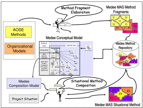
Figure 1.3 depicts the main aspects of the objective of this thesis. Firstly, the proposed solution allows a method engineer to elaborate a collection of method fragments sourced from several AOSE methods and agent organizational models, as well as to store them in a Method Repository. Such a repository could then cover most development phases and MAS components, depending on the AOSE methods and agent organizational models used as method fragment sources.
Figure 1.3: Research objectives in a diagrammatical perspective
Secondly, we propose an approach that allows a method engineer selecting the suitable
AOSE Methods Organizational Models MAS Method Fragments F1 F2 F5 F4 F3 F1 F2 F3 F4 F5 F1 F2 F5 F4 F3 F1 F2 F3 F4 F5 F1 F2 F3 F4 F5 Method RepositoryMethod Repository Method Fragment Elaboration Method Engineer Method Engineer
MAS Situational Method
Situational Method Composition Agent Agent Org Org MAS MAS Project Team MAS Project Execution MAS Project
Analysis MAS Project
Measurement
out of such fragments. In such an activity, the method engineer can eventually be helped by some members of the project team.
Thirdly, the proposed solution allows the project team, including the method engineer, to measure and analyze several quality attributes of the MAS situational method during the project execution, such as the extent in which the situational method addresses the factors that characterize the project situation and how easy it is to be understood. Finally, closing the improvement cycle, the lessons learned resulting from MAS project analysis could then be used by the method engineer to enhance the content of the Method Repository.
To the best of our knowledge, there is no research concerning MAS situational methods for building organization centered MAS as part of an improvement cycle for MAS development.
1.3.3 Research Procedure
These research objectives have been achieved by taking the following steps:
1. Definition of building blocks for composing situational methods for organization centered MAS out of method fragments. Such building blocks include Medee MAS method fragments, Medee MAS situational methods, and a situational composition model that guides the creation of MAS situational method according to a specific project situation, called Medee Composition Model.
2. Development of a MAS method repository to store both method fragments and situational methods, called Medee Method Repository.
3. Development of a procedure to populate the Medee Method Repository with MAS
method fragments captured from AOSE methods and agent organizational models, as well as composing situational methods out of these fragments. Such a procedure is called Medee Delivery Process.
4. Population of the MAS method repository with method fragments sourced from several AOSE methods and agent organizational models. Namely, Tropos, Gaia, PASSI, Ingenias, MOISE+, and OperA.
6. Design a case study to investigate the use of the proposed solution for developing organization centered MAS projects in a disciplined way, as part of an improvement cycle for MAS methods.
Figure 1.4 depicts such a research approach from a diagrammatical perspective, showing that the definition of Medee building blocks, together with the Medee Method Repository and Medee Delivery Process contribute to achieving the intermediate scenario for
developing organization centered MAS, presented in Section 1.1.2.
Figure 1.4: Main components of the research approach
Furthermore, Figure 1.4 shows that the Medee Improvement Cycle, built upon the previous propositions, contributes to reaching the ideal scenario for organization centered MAS development.
Finally, as depicted at the top of Figure 1.4, all these elements – Medee building blocks, Medee Method Repository, Medee Delivery Process, and Medee Improvement Cycle – constitute the Medee Framework that is the main contribution of this thesis.
Medee Building Blocks Medee Repository Medee Delivery Process Medee Improvement Cycle MAS Development Intermediate Scenario
Steps 1, 2, 3 and 4 Towards MAS
Development Ideal Scenario
Steps 5 and 6
Medee Framework
Medee Building Blocks Medee Repository Medee Delivery Process Medee Improvement Cycle MAS Development Intermediate Scenario
Steps 1, 2, 3 and 4 Towards MAS
Development Ideal Scenario
Steps 5 and 6
1.4 Text Structure
This doctoral dissertation consists of three parts, containing nine chapters, and three appendixes. Figure 1.5 depicts how these parts and the relating chapters are structured according to the research procedure previously presented.
Part I, which is composed of Chapters 2, 3 and 4, presents background and related work concerned with the research approach. While Chapter 2 focuses on aspects of Software Engineering that are related to the subject of this thesis, namely, software development methods and quality improvement cycle, Chapter 3 presents the main aspects of the MAS field, highlighting those closely relating to the subject of this dissertation, namely, AOSE methods and agent organizational models. Furthermore, Chapter 4 focuses on aspects of the Situational Method Engineering discipline, including concepts, meta-models, frameworks, and tools.
Figure 1.5: Dissertation Structure
Part II, which is composed of Chapters 5 and 6, describes the proposed solution itself, namely, the Medee Framework. Chapter 5 presents the main building blocks for developing organization centered MAS applications in a disciplined way. They are: Medee MAS Method Fragment, Medee MAS Situational Method, and Medee Composition Model. Chapter 6 shows
Medee Building Blocks Medee Repository Medee Delivery Process Medee Improvement Cycle Chapter 6 Chapter 5 Chapter 8 Chapter 7 Software Engineering Multiagent Systems Development Situational Method Engineering
Chapter 2 Chapter 3 Chapter 4 Part I: Background and Related Work Part II: The Medee Framework Part III: Application of Medee Framework
Medee Framework
Medee Building Blocks Medee Repository Medee Delivery Process Medee Improvement Cycle Chapter 6 Chapter 5 Chapter 8 Chapter 7 Software Engineering Multiagent Systems Development Situational Method Engineering
Chapter 2 Chapter 3 Chapter 4 Part I: Background and Related Work Part II: The Medee Framework Part III: Application of Medee Framework
how to compose and improve methods for developing this class of MAS applications, using the Medee Framework.
Part III, which is composed of Chapters 7, 8, and 9, describes the applications of the Medee Framework. Firstly, Chapter 7 shows how the Medee Framework can be populated with method fragments sourced from several MAS development approaches. Secondly, Chapter 8 presents a case study conducted to investigate the use of the Medee Framework for composing MAS situational methods, sourced mainly from Tropos, Gaia, and MOISE+. Moreover, these situational methods were used within an improvement cycle for MAS development methods. This case study, called the USP Farmer project, involved the development of organization centered MAS to solve the problem proposed by the Multiagent Programming Contest. Chapter 9 presents our conclusions, highlighting the main contributions of this work as well as some directions for future work.
Part I
Chapter 2
Software Engineering
This chapter presents the main aspects of the engineering discipline concerned with software production, namely Software Engineering. Although the huge amount of literature concerning this discipline, both in the industry and academic arenas, this chapter focuses on aspects of Software Engineering that are related to the subject of this dissertation, more precisely, software development methods and quality improvement cycle.
It is set out as follows: Section 2.1 outlines the main concepts of Software Engineering, while Section 2.2 and 2.3 detail software quality and development methods respectively. Finally, Section 2.4 discusses some of the issues relating to these aspects.
2.1 Introduction
The Institute of Electrical and Electronics Engineers (IEEE, 1990, p. 67) defines Software Engineering as the study and “application of a systematic, disciplined, quantifiable approach to the development, operation, and maintenance of software; that is, the application of engineering to software”.
In other words, Software Engineering is an Engineering discipline concerned with the practical problems of producing software, from the early phases of system specification to maintaining the system after deployment. As an Engineering discipline, Software Engineering concerns the application of theories, methods and tools where appropriate, taking into account organizational and financial constraints. Along with the technical processes of software development, Software Engineering is about the development of tools to support software production, as well as software project management (SOMMERVILLE,2007).
Thus, the main Software Engineering goal is to provide processes, methods, techniques, models, and tools to cope with the complexity inherent to the software development (SOMMERVILLE, 2007).
first two layers are based on traditional engineering1 procedures, the remainder is more dependent on software technology aspects (PRESSMAN, 2010).
This dissertation is concerned with two of these four layers - Quality Focus and Methods layers – since it proposes a method framework for developing organization centered MAS towards a continuous method quality improvement. Thus, the following paragraphs outline these four layers, while the next sections present the main conceptual aspects concerning quality focus and software development methods.
A quality focus is the basic principle that supports Software Engineering since, as an Engineering discipline, it deals with the commitment to quality, fostering a continuous process improvement culture that leads to the development of more effective approaches to building software.
Figure 2.1: Four Software Engineering layers (PRESSMAN, 2010, p.14)
Furthermore, the Processes layer aims to establish rational and timely software development, constituting the basis for management control of software projects. In resume, project management deals with planning, scheduling, managing risks, and controlling resources and costs. Sommerville (2007, p.93) points out that project management is an essential part of Software Engineering, since it aims to ensure that software projects meet their constraints, such as deadline, budget, and product quality. Moreover, he suggests that although good project management cannot assure project success, bad management usually causes project failure independently of the other three layers.
1 Engineering concerns the “application of a systematic, disciplined, quantifiable approach to structures, machines, products, systems, or processes” (IEEE, 1990, p. 30).
Quality Focus
Processes
Methods
Tools
Quality Focus
Processes
Methods
Tools
Quality Focus
Processes
The next layer - the Methods layer - is concerned with technical development methods for building software. Such methods are composed of development phases - such as requirements, analysis, design, implementation, test, and deployment- over the course of which all the artifacts encompassed in a software system are produced, like models, diagrams, source code, and machine executable code. Without a software development method, a software project is developed in an ad hoc manner. As previously mentioned, the success of a project relies on the extraordinary efforts of dedicated and well skilled individuals whenever executed in an ad hoc way. Given that it is not sustainable, software organizations should use a well-defined method to develop software systems in a repeatable and predictable way (KRUCHTEN, 2003, p.16).
Finally, the Tools layer offers support for the three previous layers. A tool is a means, that can be automated or semi automated and used to support part of the software development process (BRINKKEMPER, 1996).
Such tools, commonly called computer-aided software engineering (CASE) tools, encompass a broad range of computer programs that can be classified into three perspectives: (i) a functional perspective that groups CASE tools by functionality; (ii) a process perspective that takes into account the development phase in which tools are involved (e.g. requirements, analysis, design); and (iii) an integration perspective that aims to group tools taking into account how they are put together in integrated units that provide support for process and method activities (SOMMERVILLE, 2007).
From a functional perspective, CASE tools can be classified using the following categories (SOMMERVILLE, 2007), among others:
• planning tools: for project estimations and scheduling, such as PERT1 tools;
• change management tools: such as change control systems and requirement traceability tools;
• configuration management tools: such as version management system and system building tools;
• method-support tools: such as Unified Model Language (UML) (BOOCH; RUMBAUGH; JACOBSON,1999) based tools for graphical analysis and design;
• language-processing tools: such as compilers and interpreter tools;
• program analysis tools: such as cross reference generators and static analyzer tools;
• testing tools: such as test data generators;
• debugging tools: such as interactive debugging systems;
• re-engineering tools: such as program restructuring systems.
As previously mentioned, the next sections describe two of the Software Engineering layers in detail: the software quality focus and methods layers.
2.2 Software Quality Focus
2.2.1 Overview
The software quality focus layer aims to guide the development processes towards being more focused, repeatable, and reliable, considering both quality of the delivered software application and timeliness of delivery. Although the use of processes, methods, and tools is essential to the development of software, ensuring that a software project meets its requirements while exhibiting the technical characteristics and being executed on the scheduled period of time is not enough. Thus, such tools, methods, and processes should be built upon a continuous software process improvement in order to focus on quality commitment (PRESSMAN, 2010).
In brief, software process improvement means understanding existing development processes including: managerial control, technical methods and tools, and changing them to increase product quality, reduce development costs and time (SOMMERVILLE, 2007). Hence, software process improvements should decrease the number of defects in the software product delivered to end users, as well as the amount of rework needed due to poor product quality, and consequently leading to cost reduction in software development, maintenance, and support (PRESSMAN, 2010).
for team communication and less time is available for programming). Finally, such factors also involve development tools and working environment (SOMMERVILLE, 2007).
The following steps are suggested by Humphrey (1988) to improve the quality of a software process: (i) understanding the current software development process; (ii) developing a vision of the desired process improvement; (iii) defining the actions that are required to achieve the process improvement; (iv) establishing a plan to carry on these actions; and (v) committing resources to execute this plan. Moreover, Humphrey (1988) claims that by addressing the software production issues, the adopted process should be continually controlled, measured, and improved.
In a similar way, Sommerville (2007) suggests that software process improvement consists of a cycle composed of three main stages - Process Measurement, Process Analysis, and Process Change – as shown in Figure 2.2 (SOMMERVILLE, 2007, p. 667).
Figure 2.2: The Process Improvement Cycle (SOMMERVILLE, 2007)
As its name indicates, the Process Measurement stage deals with the measurement of current process quality attributes, as well as those attributes that characterize the (software) product generated during project execution. Measuring an attribute consists of assigning a value to it using specific metrics. A metric usually includes a scale of values (e.g. 1, 2, 3) and a value domain (e.g. poor, medium, excellent) (MENDONÇA; BASILI, 2000). The choice of which quality attributes to be measured should reflect the desired measurement goals. For instance, such goals could be related both to how understandable the process is and to process reliability, as described in Chapter 8.
The next stage, Process Analysis, consists of assessing project measures in order to Measure
Analyze Change
Measure
limitations. To be effective, a process analysis should take into account the organizational context and project environment, along with collected measures (BASILI; CALDIERA,
ROMBACH, 1994).
Finally, the Process Change stage consists of applying appropriate modifications into the current process to mitigate its weaknesses and limitations, as well as enforcing its strengths. These modifications could consist of introducing or eliminating tasks, techniques, and tools, changing the sequence of phases and activities, introducing or eliminating work products, or introducing new development roles and responsibilities.
Several frameworks for dealing with such stages of process improvement have been proposed in the Software Engineering field over the last decades. These frameworks are commonly used in the software industry to assess the maturity level of an organization’s software process and to provide a qualitative indication of such a level, like the following scale of the process maturity level (HUMPHREY, 1988): initial process (ad hoc process), repeatable process (provides basic management control), defined process (offers process definition), managed process (involves process measurement), and optimized process (involves process control). The Standard Capability Maturity Model Integration Assessment Method for Process Improvement (SCAMPI) (SEI, 2001), as proposed by the Software Engineering Institute1 (SEI), and the Software Process Improvement and Capability Determination (SPICE)2 are among these frameworks.
Moreover, less formal process improvement frameworks have been proposed, such as the Quality Improvement Process (QIP) (BASILI; SELBY; 1991; BASILI, 1993), and the Goal Question Metric Paradigm (GQM) (BASILI; WEISS, 1984; BASILI; CALDIERA; ROMBACH, 1994).
The following sections describe the QIP and GQM process improvement frameworks in detail since they have provided the backbone for defining the Medee Improvement Cycle, presented in Chapter 6.
1 The Carnegie Mellon Software Engineering Institute (SEI) was created in 1984. Its mission is to advance software engineering and related disciplines to ensure the development of software systems with improved quality, cost predictability and scheduling. For more information, see <http://www.sei.cmu.edu/>
2.2.2 Quality Improvement Paradigm
The Quality Improvement Paradigm (BASILI; ROMBACH, 1988; BASILI; SELBY, 1991;
BASILI, 1993) is an evolutionary software quality process that aims to provide a mechanism for software improvement through experimentation and reuse of project experience. Such a paradigm proposes to treat software development as empirical experiments in order to learn with them and thus improve the way to build software.
QIP is based on the following assumption: before determining which software development method should be applied, the current project must be characterized, as well as improvement targets must be set. Such characterization helps tailor the development method.
As shown in Figure 2.3, this paradigm involves six steps: (i) characterization of the current project and its environment; (ii) setting the measurement goals for project analysis; (iii) choosing the project process and method; (iv) executing the project and collecting analysis data; (v) analyzing the collected data; and finally (vi) packaging the project experience.
Figure 2.3: QIP six steps
2.2.2.1 Characterization of the Current Project and its Environment
The first step - Characterization of the current project and its environment - consists of
1. Characterizing the current project and its environment considering People, Problem, Process, Product,
and Resource factors.
2. Setting the measurement goals for the project
3. Choosing the project process and method
4. Executing the project and collecting data
5. Analyzing the collected data
6. Packaging the project experience for future use 1. Characterizing the current project and its environment
considering People, Problem, Process, Product, and Resource factors.
2. Setting the measurement goals for the project
3. Choosing the project process and method
4. Executing the project and collecting data
5. Analyzing the collected data
that each project has a particular situation, in some way distinct from other projects, such a project situation should be made explicit and taken into account during the definition of the project (measurement) goals, the choice of the appropriate development method, and the project execution itself (BASILI; ROMBACH, 1988).
Thus, project characterization aims to define the project situation in an explicit way according to the following dimensions: people, problem, product, process/method, and resources (BASILI, 1981, 1993). People factors relate to project team characteristics, like team size, team organization, levels of expertise of team members, as well as motivation, ability to communicate, previous experience with the problem domain and the target development method.
Factors relating to the problem to be solved by the software product include problem type (as mathematical, database manipulation), problem magnitude (as big, medium, small), state of the problem definition (as informal or formal specification), susceptibility of the problem to change, importance of the problem and how new it is compared to current state-of-the-art.
Product related factors encompass those relating to the software product itself. They include the number of expected deliverables, e.g. artifacts delivered at the end of the project, product size in lines of code, product structure, such as number of components or subsystems, and non-functional product aspects, such as portability, reliability, and maintainability.
Factors relating to process and method have several aspects, among them (i) the development life cycle model (e.g. waterfall, iterative), (ii) the adopted software paradigm, such as structured programming, object-oriented, agent-oriented development, and (iii) the programming language (e.g. Java, C).
Finally, resource related factors are those to do with nonhuman elements of software development such as the project budget, the project deadline, the set of development tools, as well as the computer infrastructure, such as the target machine system and the development machine system. It is worth while noticing that there is a strong relationship between resource and product factors, since resources define limits for product performance.
2.2.2.2 Setting the Measurement Goals for Project Analysis
generated during the project. Furthermore, a measurement goal can take several points of view into account, like the end user, project manager, or developer.
Examples of measurement goals are: (i) to promote method acceptability by developers to ensure it is actually followed, and (ii) to improve method visibility by emphasizing results generated for each activity to clearly show the progress of the project.
The Goal Question Metric Paradigm (BASILI; WEISS, 1984, BASILI; CALDIERA;
ROMBACH, 1994) is one of the measurement approaches that can be used in this step. Section 2.2.3 provides an overview of this paradigm.
2.2.2.3 Choosing the Project Process and Method
The third step consists of choosing and tailoring the process and method for the current project. Both of them should be tailored before being used, given that each project has particular characteristics, as previously described. Thus, this step encompasses the choice of the most appropriate process and method, as well as tailoring them to deal with the project factors better, relating to people, problems, products, process, and resources (BASILI;
ROMBACH, 1988).
It is worth noting that method tailoring is the subject of a specific engineering discipline, called Situational Method Engineering (BRINKKEMPER, 1996, HARMSEN, 1997), presented in detail in Chapter 4.
2.2.2.4 Executing the Project and Collecting Analysis Data
The fourth step consists of running the project, according to the tailored process and method, to produce the required software products. Furthermore, this step involves collecting data that will be used to analyze measurement goals already established (see second step). Additionally, this data should be validated during project execution to allow for corrective real-time actions, if necessary.
Some examples of data collected during project execution are: process related data (e.g. process conformance), product data (e.g. size and complexity), and resource data (e.g. required effort by activity and calendar time).
2.2.2.5 Analyzing the Collected Data
2.2.2.6 Packaging the Project Experience
Finally, packaging the project experience involves organizing and storing the experience acquired during the previous steps as a structured knowledge, in such a way that it can be used for future projects.
It consists of a project data analysis done after the project end, called a post-mortem analysis, which does not allow feedbacks during the own project execution.
2.2.3 Goal Question Metric Paradigm
The Goal Question Metric paradigm (BASILI; WEISS, 1984, BASILI, 1992, BASILI;
CALDIERA; ROMBACH, 1994) consists of a popular approach for defining and evaluating measurement goals. It was originally developed for NASA at the Goddard Space Flight Center to evaluate software defects, and later used to create and establish measurement programs throughout several organizations, such as HP, AT&T, and IBM (BASILI et al., 2007).
As its name indicates, GQM encompasses three main notions: measurement goal, questions of interest, and metrics. Thus, this paradigm involves identifying a set of measurement goals related to the project improvement targets, questions of interest used to refine these goals, and metrics that should be collected to answer these questions to discover whether the measurement goals have been achieved or not. Therefore, questions of interest provide a bridge between the measurement goals subjectively defined at a high level, and the metric to be collected, by forcing sharper definition of measurement goals to guide data collection and data analysis (BASILI; WEISS, 1984).
It should be mentioned that the GQM paradigm does not provide a specific measurement model composed of a set of particular measurement goals, questions and metrics. Rather, it offers an abstract structure and a procedure for stating measurement goals and refining them into questions of interest about the object to be measured (BASILI;
ROMBACH, 1987).
Figure 2.4: An abstract GQM structure composed of goals, questions and metric (BASILI, 1992)
In order to guide the definition of measurement goals, Basili and colleagues (BASILI;
CALDIERA; ROMBACH, 1994, MENDONÇA; BASILI, 2000) suggest a goal template involving four concepts - object of study, purpose, issue, and viewpoint entity – as follows:
Analyze “object of study” in order to “purpose” with respect to “issue” from the point of view of “viewpoint entity”
In such a template, an object of study specifies the target of the goal, as product, process, method, or resource, while purpose defines the reason for the measurement goal. Main reasons are characterization, evaluation, prediction, and motivation. For instance, (i) characterization purpose may help distinguishing the process and method aspects, such as tracking the process schedule, providing information on where the project stands with respect to aspects such as percent of resource use and calendar time; (ii) evaluation purpose may be used for assessing the quality of a given development method, such as showing the work productivity; (iii) prediction purpose may refer to predicting and estimating some information at later point in time; and (iv) motivation purpose can be used for letting the project team know what is important in a quantitative way.
An issuedefines the measurement goal focus. Examples of issues are cost, correctness, robustness, maintainability, and reliability. Finally, viewpoint entitydefines a particular angle for the measurement. For instance: developers, project managers, customer, and a software corporation.
An example of a measurement goal using this template is: Analyze the AOSE method for the purpose of evaluation with respect to the understandability from the point of view of the developer.
Chapter 8 presents a GQM model used in the case study conducted to investigate the
Goal 1 Goal 2 Goal 3
Question 1 Question 2 Question 3 Question 4
Metric 2 Metric 3