www.adv-radio-sci.net/4/155/2006/ © Author(s) 2006. This work is licensed under a Creative Commons License.
Radio Science
DMT transmission in the context of industrial
telecontrol applications
S. Edinger, C. Bauer, and N. J. Fliege
University of Mannheim, Chair of Electrical Engineering, Germany
Abstract.In this paper, we discuss the use of Discrete Multi Tone (DMT) modulation in the context of industrial telecon-trol applications. We highlight the specific requirements and characteristics of the telecontrol settings and present methods to cope with the environmental challenges posed. It turns out that DMT is ideally suited for the tasks at hand. Further en-hances enable our proposed system to provide superior con-nection stability even under the most adverse conditions.
1 Introduction
DMT is the wireline application of the well-known Orthogo-nal Frequency Division Multiplexing (OFDM) transmission scheme. In recent years, commercial applications of DMT such as Asymmetric Digital Subscriber Line (ADSL) have gained immense popularity. Those applications are charac-terized by high data rates and relatively short transmission loops. The use of DMT in industrial process data communi-cations and metering applicommuni-cations has not found wide-spread acceptance yet, despite its obvious beneficial aspects. This is mainly due to the fact that conventional DMT systems suffer from relatively high transmission latency. Industrial settings are characterized by relatively low data rates but long trans-mission loops, require a high degree of reliability, and pose real-time constraints.
At our chair, a DMT transceiver for deployment in indus-trial settings was developed (Bauer, 2004) tackling the short-comings of conventional DMT systems. Sophisticated signal processing methods lead to a latency-optimized design with online adaptation facilities to suddenly occurring deteriora-tions of the transmission channel. Thus, both low latency and high adaptivity are combined to demonstrate the viability of
Correspondence to:S. Edinger ([email protected])
DMT transmission for telecontrol applications with superior connection reliability.
2 System model
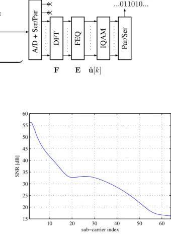
A basic model of the transmission system is depicted in Fig. 1. The binary input data stream is parallelized and par-titioned into so-called sub-carriers. Each sub-carrier i can transmit a certain number of bits bi. The block denoted QAM performs a quadrature amplitude modulation (QAM) of the bitsbi, yielding one complex valueui[k]for each sub-carrieriand DMT symbolk. The transmit signal in time do-main is generated by computing the inverse discrete Fourier transform (IDFT) over the complex frequency domain sig-nal. Transmission takes place in the baseband. Thus, only real-valued information can be transmitted. To generate a real IDFT result, a complex conjugation of the frequency-domain transmit signal has to be executed and appended to the original vector (Bingham, 1990).
The IFDT and DFT operations are usually executed with a power of 2 as input and output lengths which allows an ef-ficient computation in the form of the fast Fourier transform (FFT). Specifically, we use an FFT length of 128. Thus, at most 64 sub-carriers can be modulated independently.
The resulting transmit vector of 128 real values is prepended by a so-called cyclic prefix of 32 values which is used to prevent inter-symbol and inter-carrier interference (ISI and ICI)due to the channel impulse response. The vec-tor is converted to serial and transmitted over the channel with impulse responsehc. In this paper it is assumed that the length of the channel impulse response does not exceed the length of the cyclic prefix to preclude the occurrence of ICI and ISI.
per-...011010...
S
e
r/
P
a
r
QAM IDF
T
P
a
r/
S
e
r
+
D/
A
C G
| {z }
rAWGN
F
E
Q
E
DF
T
A/
D
+
S
e
r/
P
a
r
F
P
a
r/
S
e
r
IQAM
...011010...
rNBI hc
ˆ u[k] u[k]
Fig. 1.DMT transmission scheme.
S1 S2
AWG26
8000 ft 2000 ft
ZS= 120Ω ZL= 120Ω
1000 ft
Fig. 2.Topology of example transmission channel.
formed at the transmitter are reversed. Additionally, a one-tap frequency domain equalizer removes distortions due to the transmission channel. QAM demodulation should yield the same binary sequence that was sent by the transmitter.
3 Transmission channel
In telecontrol communications over wire lines one is faced with frequency selective channels. The impulse response of the transmission channel is determined by material con-stants of the medium and by the topology of the transmis-sion network. Sophisticated models exist that allow deriva-tion of the transfer funcderiva-tion for arbitrary topologies. Usu-ally, telecontrol applications in industrial settings use rather long transmission lines. Possibly, there are unterminated or imperfectly terminated bridge taps resulting in reflections of the transmitted data. The superposition of several reflected waves leads to a pronounced frequency selectivity of the en-countered transfer functions. However, the transfer function is slowly time-variant for wire lines. This is a great advan-tage compared to wireless communication channels which fluctuate very quickly.
The slow time variance of the transfer function allows ef-ficient use of the available resources by means of adapta-tion to the respective channel characteristics. Before actual data transmission starts, the channel is estimated during the initialization phase. A special training sequence with con-tent known to both stations is transmitted and comparison with the received sequence allows estimation of the channel attenuation factorsgi and noise powers ni per sub-carrier. Together with the reference powerprefper sub-carrier used to transmit the training sequence, the signal to noise ratios
10 20 30 40 50 60
15 20 25 30 35 40 45 50 55 60
sub−carrier index
SNR [dB]
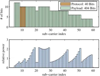
Fig. 3.SNR for example transmission channel.
(SNR) per sub-carrierican be computed as SNRi =
pref·gi
ni
(1)
4 Initial adaptation
For the rest of the paper, we will consider two stations con-nected by the topology shown in Fig. 2. Both stations are ter-minated with a resistance of 120. One unterminated bridge tap is present. Lengths of the line segments are given in feet (1 ft = 30.48 cm). The transmission wire is 26AWG. This transmission channel will be used to illustrate the techniques explained in this paper.
We assume white Gaussian background noise with power
ni=120 dBm/Hz. The total transmit power of the system is limited toptot=25 dBm. This power is equally distributed over all sub-carriers during the channel estimation phase, thuspref=ptot/128. The sampling frequency of the DMT system is fS=1024 kHz. The rather high sampling fre-quency and the short FFT length effectively reduce the la-tency of the system due to block oriented signal processing. The DMT symbol rate equalsrS=6400 Hz.
10 20 30 40 50 60 0
5 10
sub−carrier index
# of bits
Protocol: 40 Bits Payload: 404 Bits
10 20 30 40 50 60
0 1 2 3
relative power
sub−carrier index
Fig. 4.SNR for example transmission channel.
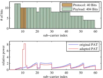
According to the SNR values computed during the initial-ization phase, a so-called bit-loading algorithm determines how many bits should be transmitted and what transmit pow-ers should be used per sub-carrier. The result of the load-ing algorithm are two tables, one indicatload-ing the bit-load (bit allocation table, BAT) and the other indicating the powers relative to the reference power (power allocation table, PAT). Our DMT system applies a modified version of the well-known Hughes Hartogs bit-loading algorithm (Hughes-Hartogs, 1989) to compute these two tables. The modifica-tion allows to specify two data classes with different tection (Hoo et al., 1999b). In transmission systems, pro-tection is usually measured and given in terms of bit error rate (BER), the number of erroneous bits divided by the total number of transmitted bits. Our system makes a distinction between protocol information used to establish and maintain the point-to-point connection of the two stations and between payload data that is transparently transmitted. Note that a temporary increase in the BER of payload data does not harm the connection itself. However, erroneous protocol informa-tion will lead to the use of defective transmission parameters and after a short time to the breakdown of the connection.
In telecontrol applications, high stability of the connection is of great concern. Hence, we provide increased protection for the protocol data. For illustration purposes, we fix the amount of protocol data to 40 bits per DMT symbol, and we call these data the embedded service channel (ESC). The target BER for the ESC is fixed to 10−7. For payload data, we set the target BER to 10−4. Again, these parameters are application dependent values. We chose values that allow for easy simulation of results. One might think of the payload information as voice data or video surveillance information, where rather high BER is acceptable.
Figure 4 shows the BAT and PAT for the above parameters that results in the maximum number of payload bits per DMT symbolbmax, in this casebmax=404.
Note that due to the use of imperfect imaging and
anti-10 20 30 40 50 60
10 20 30 40 50 60
sub−carrier index
SNR [dB]
AWGN AWGN + NBI
Fig. 5.SNR with and without additional NBI.
10 20 30 40 50 60
10−8 10−6 10−4 10−2 100
BER
sub−carrier index
actual BER target BER
Fig. 6.Change of BER due to NBI.
aliasing filters, some sub-carriers at low frequencies and high frequencies can not be used. The actual number of indepen-dently modulated sub-carriers is thus reduced to 55.
5 Appearance of disturbances
Once optimal BAT and PAT are computed and exchanged, the actual data transmission starts using these transmission parameters. The occurrence of a disturbance, e.g. an in-crease of noise power on some sub-carriers, can signifi-cantly deteriorate the transmission quality for the affected sub-carriers. An exemplary disturbance, NBI centered be-tween sub-carriers 10 and 11, is shown in Fig. 5.
Due to the deterioration of the SNR of the affected sub-carriers, the BER for these carriers rises too. The increase of BER is shown in Fig. 6, together with the target BER.
10 20 30 40 50 60 0
5 10
sub−carrier index
# of bits
Protocol: 40 Bits Payload: 404 Bits
10 20 30 40 50 60
0 2 4 6 8
relative power
sub−carrier index
original PAT adapted PAT
Fig. 7.Increase of transmit power.
This situation calls for dynamic adaptation, that is, adap-tation of the system to changed channel conditions during runtime. In ADSL, for example, a sequence of bit-swap com-mands can be exchanged to redistribute bits away from heav-ily disturbed sub-carriers to less disturbed sub-carriers (Hoo et al., 1999a). However, such methods require an exchange of protocol information over the ESC. If the ESC itself is af-fected by a disturbance, as is the case in our example, the protocol information might be faulty. In ADSL, the pro-tocol data is protected by a five-out-of-nine repetition code (ADSL). We could show in Edinger et al. (2005b) that even such protection is not sufficient. The use of faulty transmis-sion parameters will lead to a loss of connection.
The next section examines methods to restore acceptable BER for the ESC, and thus restoring reliable information ex-change, by means of signal processing.
6 Securing the ESC
A number of methods can be applied, to restore ESC qual-ity and reliabilqual-ity if it is impaired by a disturbance. Some of these methods can be applied blindly, others imply the exchange of information. Some methods work on individ-ual sub-carriers, others work on several or all sub-carriers. The amount of information exchange should be as small as possible.
6.1 Increase of transmit power
If the noise power on a sub-carrier increases by factorδn, the transmit power on this sub-carrier can be increased by the same factor to restore the target BER. Fig. 7 shows the transmit powers necessary to restore a BER of 10−7for the ESC in the presence of the example disturbance.
Note the large power peaks at affected ESC carriers. If power spectral density (PSD) constraints restrict the
max-10 20 30 40 50 60
0 5 10
sub−carrier index
# of bits
Protocol: 28 Bits Payload: 404 Bits
10 20 30 40 50 60
0 1 2 3
relative power
sub−carrier index
Fig. 8.Reduction of constellation size.
imum transmit power level, the above constellation might violate those constraints. Additionally, since total transmit power is limited, the additional power for the ESC must be collected from payload sub-carriers, which further increases their BER. Another drawback of this method is that good es-timates of the noise power must be available for determining the additional transmit power required. These estimates are not immediately available but must be gathered from obser-vations of the noise process which adds to the time required for adaptation.
6.2 Reduction of constellation size
When the number of bits on a sub-carrier is reduced by 2, this corresponds to an increase of transmit power by≈6 dB. Thus, the constellation size of disturbed ESC sub-carriers can be reduced until the amount of bits equals zero or the required transmission quality is met again. However, dy-namically reducing the amount of ESC information per DMT symbol significantly increases the complexity of the underly-ing protocol. Information might need to be spread over sev-eral symbols and recombined after reception.
Figure 8 shows the changed BAT that is required to reach BER of the ESC of equal or less than target BER. A reduction of the ESC by 12 bits is necessary.
Figure 9 compares the two above methods in terms of the actual BER they obtain. It can be seen that power adapta-tion exactly reaches the target BER. Due to limited transmit power the BER of payload sub-carriers is increased. Note that the BAT does not change. Only the updated PAT values for the ESC must be exchanged, the remaining PAT entries can be computed from those values.
10 20 30 40 50 60 10−15
10−10 10−5
BER
sub−carrier index
target BER bit removal power increase
Fig. 9.Comparison between ESC protection methods.
represented more compactly than PAT entries. However, the resulting BER are much lower than actually required. This indicates an inefficient use of the available resources. 6.3 Change of ESC location
So far, we have only considered methods that leave the spec-tral location of the ESC untouched. Clearly, this is unfa-vorable if this spectral location is affected by a disturbance. Therefore, a mere re-allocation of the ESC at sub-carriers further away from the disturbed frequency range can signif-icantly improve the BER for the ESC. One possible alterna-tive ESC location is depicted in Fig. 10. Note that complete updated BAT and PAT are used. The spectral range previ-ously occupied by ESC information is now filled with pay-load data.
Figure 11 shows the resulting BER. Requirements are al-most perfectly met for the ESC. Now, payload data is heavily affected by the disturbance. However, this does not lead to a loss of connection. Additionally, due to the use of a new BAT, the amount of payload bits is reduced by 2. This pay-load rate reduction must either be handled by higher protocol layers, or one can insert dummy bits at the receiver which will have BER 0.5 in the mean.
6.4 Precomputation of alternative ATs
The main drawback of the last alternative was the necessity to exchange complete BAT and PAT. The amount of infor-mation is considerable and impractical if the connection is disturbed. One solution for this problem is to precompute a number of alternative BAT and PAT with the ESC located on disjunct and coherent sets of sub-carriers. These alloca-tion tables (AT) are then exchanged and stored for later use in both stations. If the ESC is disturbed in its present loca-tion, an alternative AT can be used instead. The information required is then just an index pointing out the respective AT that should be chosen.
10 20 30 40 50 60
0 5 10
sub−carrier index
# of bits
Protocol: 40 Bits Payload: 402 Bits
10 20 30 40 50 60
0 1 2 3 4
relative power
sub−carrier index
Fig. 10.New spectral location for ESC.
10 20 30 40 50 60
10−8 10−6 10−4 10−2 100
BER
sub−carrier index
actual BER target BER
Fig. 11.BER with new spectral location for ESC.
Even if no reliable communication is possible for some time, both stations can cycle through all possible transmit and receive combinations to finally guess the optimal choice of AT blindly.
If some a-priori information is available about the types and likely locations of disturbances to be expected for the transmission channel or environment that the stations are pre-sented with, this information can be used to design the alter-native AT especially for those situations.
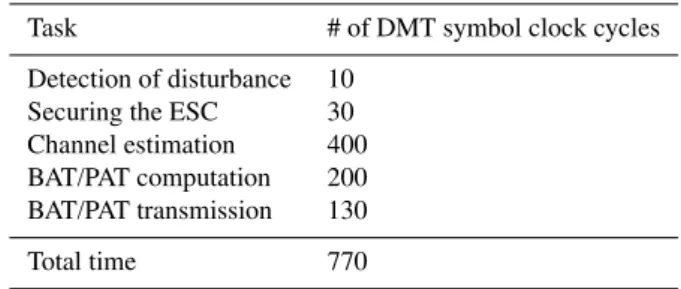
Table 1.Duration of adaptation tasks.
Task # of DMT symbol clock cycles
Detection of disturbance 10
Securing the ESC 30
Channel estimation 400 BAT/PAT computation 200 BAT/PAT transmission 130
Total time 770
protocol continues with other methods, until the connection is finally secured.
7 Completing the adaptation process
After BER of the ESC has been restored to allow reliable in-formation exchange, the adaptation process continues with estimating the transmission channel again. Data about the changed noise conditions can be gathered using decision feedback methods. However, this might lead to misestima-tion especially for heavily disturbed sub-carriers. A better but more costly alternative is to insert known training pat-terns into the DMT symbol. The effective payload data rate will be reduced by this method.
After information about the changed SNR conditions have been gathered, a new BAT and PAT with respect to these new SNR values are computed and exchanged over the ESC to-gether with a time stamp indicating when the new transmis-sion parameters will take effect. Most probably, the new amount of payload data that can be transmitted per DMT symbol will be reduced. Thus, higher protocol layers must provide some capability to accommodate changes in data rate. The BER for both payload and ESC data will perfectly meet the target values, provided the channel estimation is sufficiently accurate.
8 Simulation results
Our simulations have shown that the above protection meth-ods in connection with the incremental ARQ are extremely robust and powerful. The complete adaptation process runs also very fast. Table 1 lists the individual tasks required for the adaptation together with the number of DMT sym-bol clock cycles typically required for these tasks.
At the rate of 6400 DMT symbols per second used by our system, the complete adaptation requires only 0.12 seconds. In comparison, re-establishing a lost connection requires at least one second. Additionally, during that time, no payload data at all can be transmitted while our system still allows transmission of considerable amounts of payload data even during adaptation.
For the example disturbance and power increase for the ESC, the mean BER for the payload data equals 5.0·10−4. For the method of changing the ESC location, this mean BER equals 3.17·10−3. However, the former method requires ac-curate data about the disturbance which will not be avail-able immediately. Additionally, information exchange must take place over the disturbed ESC. Both factors require time which is not needed for the latter method. Thus, both will be approximately equal in the amount of erroneous bits received but the latter will complete sooner.
Whichever method is applied, it becomes clear that even in the presence of disturbances, the mean BER of payload might allow relatively unhampered transmission during the adaptation process.
9 Conclusions
Our proposed system makes effective use of the multiple benefits of DMT modulation and alleviates its few disadvan-tages. The system has superior connection stability even in the presence of strong disturbances. It can recover extremely quickly from such disturbances. Finally, it is very flexible and can easily be fine tuned to meet specific requirements.
Acknowledgements. This work was partly founded by the German Research Foundation (Deutsche Forschungsgemeinschaft, DFG).
References
ADSL: AMERICANNATIONALSTANDARD FORTELECOMMUNI
-CATIONS: Asymmetric Digital Subscriber Line (ADSL) Metallic Interface Specification, Tech. rep., Alliance for Telecommunica-tions Industry SoluTelecommunica-tions, 1998.
Bauer, C.: Mehrtr¨ager- ¨Ubertragungssysteme mit dynamischer Adaption an zeitvariante Kanaleigenschaften, Dissertation, Uni-versit¨at Mannheim, 2004.
Bingham, J. A. C.: Multicarrier Modulation for Data Transmission: An Idea Whose Time Has Come, IEEE Communications Maga-zine, Vol. 28, No. 5, 5–14, 1990.
Edinger, S., Bauer, C., Gaida, M., and Schwarz, J.: Quality of Service and Dynamic Adaptive Discrete Multitone Modulation, in: Proc. IEEE International Workshop on Spectral Methods and Multirate Signal Processing, SMMSP, Riga, Latvia, 2005a. Edinger, S., Schwarz, J., and Fliege, N. J.: Protected Protocol
Se-curing Transition Phases in Dynamically Adaptive OFDM Sys-tem, in: Proc. of the International OFDM Workshop, InOWo, Hamburg, Germany, 2005b.
Hoo, L., Salvekar, A., Aldana, C., Cioffi, J. M., Chow, P., and Carlo, J.: Express and Confirmation AOC Swapping Commands for DMT DSLs, ANSI Contribution T1E1.4/99-118, 1999a. Hoo, L. M. C., Tellado, J., and Cioffi, J. M.: Discrete Dual QoS
Loading Algorithms for Multicarrier Systems, Proc. IEEE Inter-national Conference on Communications, ICC, Vol. 2, 796–800, 1999b.