Vol. 3, No. 1, June 2006, 89-101
89
On-Line Monitoring of Multi-Area
Power Systems in Distributed Environment
Ramadoss Ramesh
1, Velimuthu Ramachandran
2Abstract: The main objective of this paper is to develop a distributed model using grid environment through which on-line monitoring of multi-area power systems can be carried out continuously. Grid computing is a viable solution in order to exploit the enormous amount of computing power available across Internet to solve large interconnected power system problems. A grid service model is proposed for on-line monitoring of multi-area power systems, which provides solutions at specific intervals of time. The proposed model is designed in such a way that any node in the grid can provide the service, which can obtain the power system data from other client grid nodes and responds with solution. Hence the proposed model is highly distributed and has inherent features of scalability and reliability implicitly.
Keywords: Grid Computing, Grid Service and On-line Load flow monitoring, On-line dynamic security analysis, real time economic load dispatch (ELD).
1
Introduction
The power system operation and control needs huge volume of data where a new approach is needed to enable the power system data to be processed, analyzed and interpreted by different power system clients. Existing power system simulations are primarily desktop applications with a small number of exceptions implemented on parallel processing computers. The existing Web enabled models for power system operations are mainly concerned with exchange of information and do not provide quick and reliable solutions to power system problems. The exchange of computing power is inherent to grid environment and hence quicker and fault tolerant models for power system operations can be proposed for design and implementation. An attempt is being made in this model to create a grid environment for on-line monitoring of multi-area power systems in which the grids are clusters of interconnected computers that can collectively provide quicker access to very large power system data.
1Ramanujan Computing Centre, Anna University, Chennai-25, E-mail: [email protected] 2
Chen and Lu [2] demonstrated the potential advantages of the Web as the platform for developing and deploying complex power system simulations by using the distributed technologies and model-view controller concepts. Since the existing Supervisory Control And Data Acquisition Systems (SCADA) were developed based on different platforms using different languages, the authors Qui et. al. [3] proposed an Internet based SCADA display system and tried to solve the legacy issues using Java Native Interface (JNI), which is really a tedious process. An RMI (Remote Method Invocation) based single-server/mul-tiple-clients architecture has been proposed by Nithiyananthan and Ramacha-ndran [4] in such a way that for every specific period of time, the remote server obtains the power system data simultaneously from the neighboring power systems which are the clients registered with the remote load flow server and the load flow solutions from the server have been sent back to the respective clients.
A complete Web based, platform independent power system simulation package with various analyses distributed in a clustered environment has been modeled by Irving et.al. [7]. Sando et. al. [6] demonstrated through experimental results that online security analysis could be executed in lesser period of time even for large power system. In future every electrical generator will be equipped with computational and communication facilities. Grid computing can provide a relatively inexpensive new technology allowing the output of embedded generators to be monitored. The ability of grid enabled systems to interact autonomously will be vital for small generators where manned operation is unlikely to be viable.
The rapid developments of the Internet and distributed computing have opened the door for feasible and cost effective solutions for multi-area power system problems. All these involve an access to heterogeneous, distributed, massive dataset and computation. The proposed grid service model provides a distributed solution to handle the above complexities. Even though, there are many architectural models for solving multi-area power systems, the proposed grid service model for on-line monitoring of multi-area power systems is more powerful and flexible since it provides standard technology and platform for heterogeneous systems.
2
Grid Infrastructure for On-Line Monitoring of
Multi-Area Power Systems
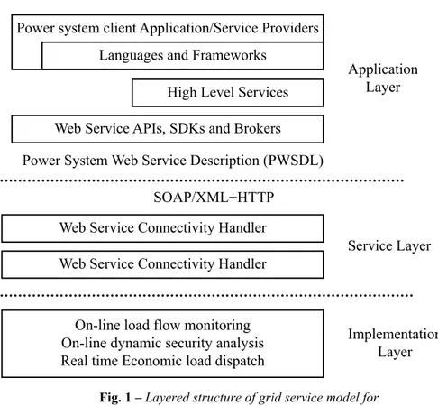
Web Service Connectivity Handler Web Service Connectivity Handler SOAP/XML+HTTP
Power System Web Service Description (PWSDL) Web Service APIs, SDKs and Brokers
High Level Services Languages and Frameworks
Power system client Application/Service Providers
Application Layer
Service Layer
Implementation Layer On-line load flow monitoring
On-line dynamic security analysis Real time Economic load dispatch
Fig. 1 – Layered structure of grid service model for on-line monitoring of multi-area power systems.
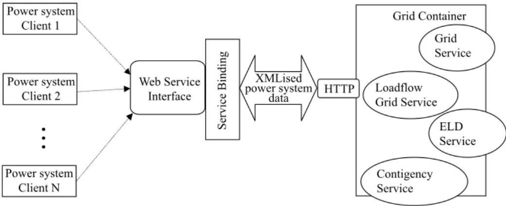
Based on the above grid service model, a distributed environment has been set up to monitor the operations of multi-area power systems. Each sub system of an interconnected power system has been considered as a power system client and registered with a grid node, which acts as a server. The power system data have been represented in XML and the XMLised data is packaged in a SOAP envelope and sent over HTTP transport. The proposed grid service model exchanges the power system data and the results in which the power system client need not send the request every time. The proposed model is highly interoperable since the power system data and the operational behaviors are represented in XML. Power system client framework and the grid container that encapsulate power system web services for on-line monitoring of multi-area power systems is shown in Fig. 2.
Object Access Protocol (SOAP) transport for transmitting XMLised power system data. The proposed grid service model for on-line monitoring of multi-area power systems is plugged into the Open Grid Service Architecture (OGSA) framework along with the service description module and then the load flow grid service, contingency service and economic load dispatch (ELD) have been deployed.
Power system Client 1
Power system Client 2
Power system Client N
…
Web Service Interface
Service B
ind
ing
XMLised power system
data
HTTP
Grid Container
Grid Service
Loadflow Grid Service
ELD Service
Contigency Service
Fig. 2 – Client Side framework and container model for on-line monitoring of multi-area power systems.
3
Grid Service Model For Distributed
On-Line Load Flow Monitoring
The load flow grid service implementation is an addressable, and potentially stateful. An instance of the LoadFlowGridService object as shown in the application layer of Fig. 1 implements an interface as described by power system web service description portTypes. The power system web service description is extracted from the proposed GWSDL load flow service module. The load flow service and its bindings are then created. The default behaviors of the Open Grid Service Infrastructure (OGSI) are imported to enhance the proposed services. The load flow grid service port defines an individual endpoint by specifying a single address for the binding. The binding attribute refers the linking rules as defined by power system web service description portTypes. The SOAP request has been sent to a LoadFlowGridService through the SOAP HTTP binding.
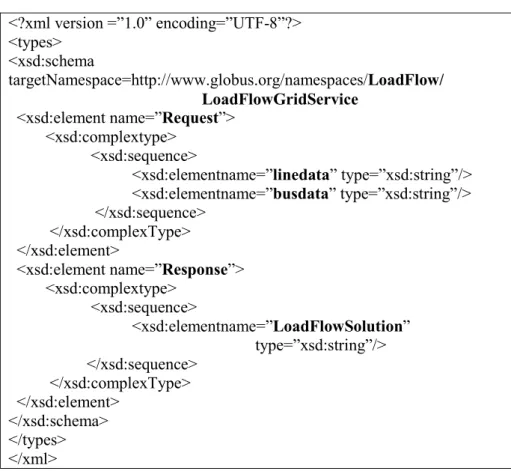
The GWSDL code for the load flow grid service is shown in Fig. 3.
3.1 Load Flow Service Implementation
interface as imported from OGSI that facilitates the creation of proxy for the conversion of Grid Service Handle (GSH) to a Grid Service Reference (GSR). It uses the SOAP binding for invoking the load flow service implementation. A data virtualization service has been utilized to register the load flow component using the built-in naming context and to identify the location of the server grid node in order to obtain the service.
Fig. 3 – A Sample GWSDL code for on-line load flow monitoring,
3.2 Load Flow Service factory creation
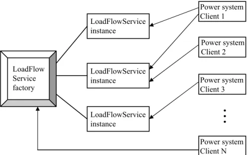
Grid services which are basically Web services with improved characteris-tics and services. Web services are stateless and non-transient. The Grid services solve both the problem by proposing a factory service approach to Web service. Instead of having one big stateless LoadFlowService shared by all power system clients, a central LoadFlowService factory has been created, which is in charge of maintaining a bunch of LoadFlowService instances. The load flow service factory and instance model is shown in Fig. 4.
<?xml version =”1.0” encoding=”UTF-8”?> <types>
<xsd:schema
targetNamespace=http://www.globus.org/namespaces/LoadFlow/ LoadFlowGridService
<xsd:element name=”Request”> <xsd:complextype>
<xsd:sequence>
<xsd:elementname=”linedata” type=”xsd:string”/> <xsd:elementname=”busdata” type=”xsd:string”/> </xsd:sequence>
</xsd:complexType> </xsd:element>
<xsd:element name=”Response”> <xsd:complextype>
<xsd:sequence>
<xsd:elementname=”LoadFlowSolution” type=”xsd:string”/>
</xsd:sequence> </xsd:complexType> </xsd:element>
LoadFlow Service factory
LoadFlowService instance
LoadFlowService instance
LoadFlowService instance
Power system Client 1
Power system Client 2
Power system Client 3
Power system Client N
…
Fig. 4 – Load flow service factory and instance.
When a power system client wants to invoke a LoadFlowService operation, it will talk to the instance, not to the factory. When power system client needs a new instance to be created, it will talk to the factory. One instance could be shared by two power system clients, and one power system client could have access to two instances.
3.3 Load flow service parameters description
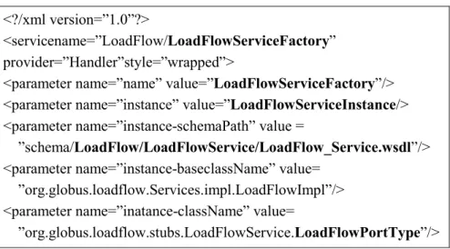
The various parameters needed for the load flow service deployment are described using Web Service Deployment Descriptor (WSDD). A service factory is created within the grid service container, which is used to create in-stances of a load flow grid service. Each load flow grid service instance has a unique identity with respect to the other instances in the container. The parameters used for load flow grid service deployment in grid container are defined in WSDD as shown in Fig. 5.
3.4 Load flow grid service stubs creation
The stub, which is the client side proxy of the load flow grid service remote object, has been built and it is added to the Grid Archive (GAR) file. The GAR file contains all the stubs necessary for the load flow service implementation. The load flow service can be deployed into the grid service container using this GAR file.
Fig. 5 – WSDD for load flow grid service deployment.
3.5 Power System Client Application
The power system client application invokes “load flow grid service” requests on the load flow service factory interface to create a new service instance. The newly created load flow service instance will be automatically assigned a globally unique name called GSH, which is used to distinguish this specific service instance from other grid service instances. In addition to using a GSH, the load flow grid service instances are made accessible to client applications via the use of a GSR. The power system client uses the GSR to send request directly to the specific instance and hence the load flow solutions are obtained as response.
The hierarchical steps involved in execution of the load flow grid service are detailed as follows:
• Start the grid service container.
• Start the power system client (Any number of clients may be considered).
• Power system client creates a new instance of LoadFlowGridService from the central LoadFlowService Factory.
<?/xml version=”1.0”?>
<servicename=”LoadFlow/LoadFlowServiceFactory” provider=”Handler”style=”wrapped”>
<parameter name=”name” value=”LoadFlowServiceFactory”/> <parameter name=”instance” value=”LoadFlowServiceInstance/> <parameter name=”instance-schemaPath” value =
”schema/LoadFlow/LoadFlowService/LoadFlow_Service.wsdl”/> <parameter name=”instance-baseclassName” value=
”org.globus.loadflow.Services.impl.LoadFlowImpl”/> <parameter name=”inatance-className” value=
• Grid server node uses the power system client’s reference to receive the load flow data from that client and computes the load flow solution.
• Client obtains the result and provides a view of the results through an user Interface.
• For every specific interval of time, the server grid node automatically receives load flow data from the client, thereby provides an automatic on-line load flow monitoring.
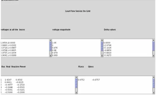
The load flow analysis was carried out using the proposed grid model on a 6-bus power system and the load flow solutions has been shown in Fig. 6
Fig. 6 – Load flow solution – Power system client’s view.
4
Grid Service Implementation for
On-Line Dynamic Security Analysis
The load flow grid service has been configured to be a notification sink and
Fig. 7(a) – Grid service container with its Notification client – Client’s view.
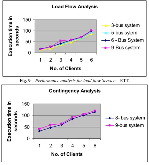
Even a fairly small power system with fewer buses will have numerous possible contingencies, which have to be ranked for selection and analysis. Doing this periodically is possible only through computing on-line with available power system data. So an efficient grid service model has been developed as described above to carry out the on-line dynamic security of multi area power systems. The dynamic security study was carried out using the proposed grid model for 6, 9, 10 and 13 bus sample systems. The grid services container running with all the services deployed in it. The clients are listening for notification. After the line outage information known to load flow client, load flow client notifies the changes. This information is used by the contingency service to carry out the contingency analysis. The analysis for a specific 6 -bus power system client is shown in Figs. 7a and 7b.
5
Grid Service Implementation for Real Time
Economic Load Dispatch
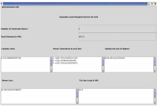
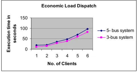
Economic dispatch problem of power systems is to determine the optimal combination of power outputs for all generating units, which minimizes the total fuel cost while satisfying the constraints. The economic load dispatch was carried out using the proposed grid model on different sample power system and economic load dispatch solution of 3-bus system has been shown in Fig. 8.
Any number of power system clients can be served without limit. When the server receives data from the power system client, it runs the required service automatically and the result is sent back to the respective power system client. Using this model, different power system clients can obtain the different services continuously at regular time intervals.
6
Performance Analysis
Any number of power system clients can be served without limit. When the load flow server receives data from the power system client, it runs the load flow solution automatically and the result is sent back to the respective power system client. Using any one of these models, different power system clients can monitor the load flow solutions continuously at regular time intervals.
Load Flow Analysis
0 50 100 150
1 2 3 4 5 6
No. of Clients
E x e c u ti o n t im e i n s e c o n d
s 3-bus system
5-bus sytem 6 - Bus System 9-Bus system
Fig. 9 – Performance analysis for load flow Service – RTT.
Contingency Analysis
0 50 100 150
1 2 3 4 5 6
No. of Clients
E x e c u ti o n t im e i n s e c o n d s
8- bus system 9-bus system
The performance of the proposed load flow fault tolerant model has been analyzed and compared using different power system networks such as 3-bus system with 3 lines, 5 -bus system with 7 lines, 6 -bus system with 8 lines and 9-bus system with 17 lines. The round trip time (RTT) has been taken as the para-meter for comparison and the results are shown in the Fig. 9.
Economic Load Dispatch
0 50 100 150
1 2 3 4 5 6
No. of Clients
E x e c u ti o n t im e i n s e c o n d s
5- bus system 3-bus system
Fig. 11 – Performance graph for Economic Load Dispatch Service.
7
Conclusion
An efficient grid service model has been developed to carry out on-line monitoring of multi area power systems. The system provides excellent scalability, high security and has a capacity to meet the huge computation requirement, which is suitable to carry out on-line monitoring for large intercon-nected multi-area power systems. The practical implementation of this approach suggested in this paper has been assessed based on different sample power systems. The proposed model can be suitably implemented for a large power system network spread over a large geographical area.
8
References
[1] Bin Qiu et.al.: Internet based SCADA display system, IEEE Trans. On Computer
applications in power, 15, Issue 1, pp. 14-19, 2002
[2] S. Chen, F.Y. Liu: Web Based Simulations of Power Systems, IEEE Trans. on Computer
Applications in Power, 15, Issue 1, 35-40, 2002.
[3] M. Di Santo, N. Ranaldo, D. Villacci, E. Zimeo: Performing Security Analysis of Large
Scale Power Systems with a Broker-based Computational Grid, IEEE Proceedings of ITCC2004, 2, 77-82, 2004.
[4] M. Irving, G. Taylor, P. Hobson: Plug in to Grid Computing, IEEE Trans. on Power and
[5] M. Irving, G. Taylor: Prospects for Grid-Computing in Future Power Network’s, Discussion Paper circulated by Brunel Institute of Power Systems 15/09/03.
[6] K. Nithiyanatan, V. Ramachandran: RMI Based Multi-Area Power System Load Flow
Monitoring, IJECE, 3, No. 1, pp. 28-30, 2004.
[7] B. Qui, H.B. Gooi: Web based SCADA display system for access via Internet, IEEE Trans.
On Power Systems, 15, 681-686, 2000.
[8] http://www.globus.org
[9] http://java.sun.com