O R I G I N A L A R T I C L E S UDC: 616.314-76/-77 DOI: 10.2298/VSP150105089P
Measurement of the accuracy of dental working casts using a
coordinate measuring machine
Ispitivanje preciznosti radnih modela pomo
ć
u koordinatne merne mašine u
stomatologiji
Michal Potran*, Branko Štrbac†, Tatjana Puškar*, Miodrag Hadžistević†, Janko Hodolič†, Branka Trifković‡
*Department of Dentistry, Faculty of Medicine, University of Novi Sad, Novi Sad, Serbia; †Department of Production Engineering, Faculty of Technical Sciences, University of Novi Sad, Novi Sad, Serbia; ‡Clinic for Prosthodontics, Faculty of Dental
Medicine, University of Belgrade, Belgrade, Serbia
Abstract
Background/Aim. Dental impressions present a negative im-print of intraoral tissues of a patient which is, by pouring in gypsum, transferred extraorally on the working cast. Casting an accurate and precise working cast presents the first and very important step, since each of the following stages contributes to the overall error of the production process, which can lead to inadequately fitting dental restorations. The aim of this study was to promote and test a new model and technique for in vitro
evaluation of the dental impression accuracy, as well as to asses the dimensional stability of impression material depending on the material bulk, and its effect on the accuracy of working casts. Methods. Impressions were made by the monophasic technique using the experimental master model. Custom trays with spacing of 1, 2 and 3 mm were constructed by rapid pro-totyping. The overall of 10 impressions were made with each custom tray. Working casts were made with gypsum type IV. Measurement of working casts was done 24 h later using a co-ordinate measuring machine. Results. The obtained results show that the working casts of all the three custom trays were in most cases significantly different in the transversal and sagit-tal planes in relation to the master model. The height of abut-ments was mainly unaffected. The degree of convergence showed certain significance in all the three custom trays, most pronounced in the tray with 3 mm spacing. Conclusion. The impression material bulk of 1–3 mm could provide accurate working casts when using the monophasic impression tech-nique. The increase of the distance between abutment teeth in-fluences the accuracy of working casts depending on the mate-rial bulk.
Key words:
denture bases; denture design; elastomers; computer-aided design; sensitivity and specificity.
Apstrakt
Uvod/Cilj. Otisak predstavlja negativ intraoralnih tkiva, č i-jim se izlivanjem u gipsu njihova morfologija prenosi eks-traoralno na budući radni model. Sa laboratorijskog aspekta izrade zubnih nadoknada, izlivanje tačnog i preciznog rad-nog modela predstavlja prvi i veoma bitan korak, pošto sva-ka sledeća faza doprinosi daljem povećanju greške tokom iz-rade, što za krajnji ishod može imati neodgovarajuću zubnu nadoknadu. Cilj istraživanja bio je da se ispitaju novi model i tehnika za in vitro procenu preciznosti zubnih otisaka, kao i da se odredi uticaj količine otisnog materijala na dimenzionu stabilnost otisaka i preciznost izrade radnih modela. Meto-de. Za uzimanje otisaka korišćena je monofazna tehnika otiskivanja. Individualne kašike sa međuprostorom od 1, 2 i 3 mm napravljene su aditivnom tehnologijom za brzu izradu prototipova. Sa svakom kašikom napravljeno je po 10 otisa-ka. Radni modeli izlivani su u gipsu tipa IV. Merenje radnih modela vršeno je nakon 24 sata na koordinatnoj mernoj ma-šini. Rezultati. Rezultati pokazuju da radni modeli naprav-ljeni pomoću sve tri individulane kašike u transverzalnoj i sagitalnoj ravni značajno odstupaju od glavnog dela modela. Visina patrljaka je u većini slučajeva bila kao na glavnom modelu. Stepen konvergencije pokazao je određena odstu-panja samo kod kašike sa međuprostorom od 3 mm. Zak-ljučak. Monofazna tehnika otiskivanja i otisni materijal deb-ljine od 1 do 3 mm obezbeđuju izradu preciznih radnih mo-dela. Rastojanje između zubnih patrljaka utiče na preciznost izrade radnih modela u zavisnosti od količine otisnog mate-rijala.
Ključne reči:
zubna proteza, baze; zubna proteza, oblikovanje; elastomeri; kompjutersko oblikovanje; osetljivost i specifičnost.
Do-Introduction
Dental impressions present a negative imprint of intrao-ral tissues of a patient which is, by pouring in gypsum, tran-sferred extraorally on the working cast. From the laboratory perspective of dental restorations manufacturing, casting an accurate and precise working cast presents the first and very important step, since each of the following stages contribute to the overall error of the production process and can lead to inadequately fitting of dental restorations 1.
Making an impression is a clinically challenging procedure which is influenced by numerous factors of the oral environment, as well as the properties of the material itself. Examining the factors that influence the accuracy of dental impressions can be conducted in two ways, by direct mesurement of the impression, or by measurement of the appropriate working cast. Both methods have their advantages and limitations. The first method provides direct data about the condition of the impression material, thus avoiding superimposition of further errors. Limitations are related to the use of contactless measurement, which is affected by a small measurement field, software processing and adequate optical characteristics of the impression material 2–4. The second method, measurement of the working casts, provides a wider range of possibilities regarding the measurement technique. Both contact and contacless measurement can be used, with ease of access for manipulation with measurement object 5. Superimposition of errors, when casting a gypsum model, can be minimised by fixing the experimental conditions with equal casting protocols for all of the investigated dental impressions. Although making of the gypsum working cast prolongs the time and effort needed to obtain necessary data, it is a reference base for manufacturing of dental restorations and as such, provides better insight when assesing the discrepancies of future dental restorations.
Determination of accuracy of dental impressions requires a complex model that can replicate in vivo conditi-ons of making of dental impressiconditi-ons, with the accuracy and precision of in vitro investigation. Earlier studies included a variety of models that consisted of custom blocks, cylinders, single or several abutment teeth and complete edentulous jaws of various materials 5–11. Regarding this, there is the ne-ed for a reliable experimental model, which combinne-ed with a corresponding measurement instrument, could overcome the difficulties of data interpolation between laboratory conditi-ons and clinical practice. The two should complement each other, forming a complex model for data acqusition. From this point of view, the use of a coordinate measuring machi-ne (CMM) was chosen due to the possibility of the accurate and precise three-dimensional (3D) measurement 12, 13.
Previous studies that investigated the influence of mate-rial bulk on the accuracy of working casts were conducted using a measurement microscope and included only two di-mensional measurements 14–16. Also, the models used consis-ted of one to several abutment teeth, while as to our knowledge, the influence of material bulk on partially eden-tulous dental arch model has not been made 14–18. A more
de-tailed analysis requires a model more similar to the intraoral conditions, since the accuracy of impressions depends on the material bulk which changes with spacing between the rema-ining teeth 19. The possibility of an independent 3D analysis by CMM for each of the segments of the working casts was considered to be an improvement compared to the previous studies.
Additionally to the previous studies, we aimed to incorpo-rate another use of rapid prototyping (RP) technology in the fi-eld of dentistry. Making impressions with RP made custom trays is a new attempt to investigate the use of computer-aided design/computer-aided manufacturing (CAD/CAM) technology into a broader perspective of dental practice. The rapid prototyping technique was chosen with the aim of avoiding pos-sible distortions of the material that can occur in standard acrylic custom trays, and providing a stable base for the impression ma-terial 20. Thus, the aim of this study was to promote and test a new model and technique for in vitro evaluation of the dental impression accuracy, as well as to asses dimensional stability of elastomeric impression material in reference to the material bulk, by examining working casts with CMM.
Methods
Measurement of the experimental master model and construction of custom trays
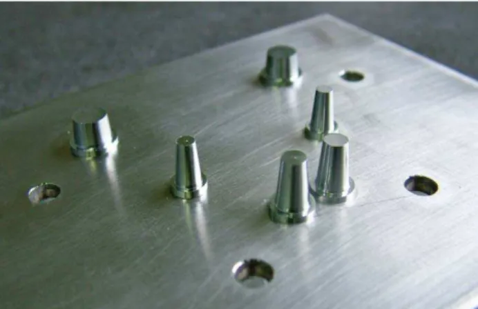
For the purpose of this study, an experimental metal master model which consisted of six abutment teeth was constructed. It presented the upper jaw with two central incisors, canines and first molars (Figure 1). Dimensions of the teeth were taken from literature and reduced by the amount of tooth substance expected to be removed with grinding 21. The taper was set at 6°. The master model consisted of an assembly with machined components. Geometry of the master model and generation of computer numerical control machines (CNC) code was designed by the CAD/CAM system.
Fig. 1 – The experimental master model.
the resulting mean values of parameters of measurement were calculated. Nominal dimensions of the CAD model were corrected using mean values and were subsequently used to create a custom tray model as a negative of the pre-vious CAD model. Physical models of custom trays with 1, 2 and 3 mm spacings for the impression material, were cons-tructed by rapid prototyping (Z310 plus, 3D Systems, USA). The powder used was gypsum based (zp 131), with a binder (zb 60) and two component epoxy resin as the filler (s5000), presented at Figures 2 and 3.
Fig. 2 – Custom trays with 1, 2 and 3 mm spacing made by rapid prototyping.
Fig. 3 – Custom tray seated on the top of the experimental master model.
Impression technique
Impressions were made using a monophasic technique with silicone addition. Due to the micromechanical retention of the impression material to a custom tray, which is the re-sult of the successive layering technique of rapid prototyping, the tray adhesive was not used. The impression
material was automixed (Elite Hd + regular, Zhermack, Italy), working time was set to 60 sec. Making of impressi-ons was conducted at room temperature (23°C), retention of the tray was done with the weight of 1 kg. Setting time was set at 10 min, overall of 10 impressions were made with each custom tray. Due to the expected viscoelastic recovery of the impression material, pouring of gypsum was delayed by 30 min. Working casts were made with the gypsum type 4 (Elite rock, Zhermack, Italy) and were allowed to set for 1 h before the impression was removed. Measurement of the working casts was done 24 h later on CMM.
Measurement of working casts on a coordinate measu-ring machine
Measurement of working casts was conducted under the same conditions as those of the master model. Inspection was conducted conformant to the new generation of product geometry specification (GPS) 22. This was based on the fact that the model consisted of geometric primitives (cones, cylinders and planes). Each geometric primitive was measu-red in a finite number of discrete points randomly arranged on the primitive surface. The measurement strategy of the cone (abutment) contained 100 measurement points, 50 po-ints for measurement of cross-section plane between the cone and the cylinder (abutment and chamfer) and 50 for rement of the cylinder (chamfer). The output of this measu-rement included the coordinates of all measumeasu-rement points which were subsequently used to generate associative geometry of the primitives. Furthermore, the software analysis was used to determine all geometric characteristics (size, angle, form, orientation, location) according to the spe-cification requirements.
Parameters, X1-3 and Y1-6, represented the axial
distan-ces which were derived features from the cone. The axial distances were observed on the cross-sectional plane which passed through the base of the abutments. Parameters deno-ted as Z1-6, were determined as the distance between two
pla-nes which limited the abutment vertically, while α1-6
repre-sented the degree of convergence and was directly derived from the abutment measurement (Figure 4).
The presence of measurement uncertainty was disregar-ded due to the fact that all working casts were measured in
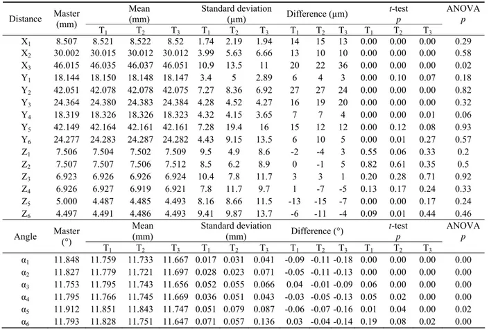
Table 1 Results of the measurement
Mean (mm)
Standard deviation
(µm) Difference (µm)
t-test p
ANOVA p Distance Master
(mm)
T1 T2 T3 T1 T2 T3 T1 T2 T3 T1 T2 T3
X1 8.507 8.521 8.522 8.52 1.74 2.19 1.94 14 15 13 0.00 0.00 0.00 0.29 X2 30.002 30.015 30.012 30.012 3.99 5.63 6.66 13 10 10 0.00 0.00 0.00 0.58 X3 46.015 46.035 46.037 46.051 10.9 13.5 11 20 22 36 0.00 0.00 0.00 0.02 Y1 18.144 18.150 18.148 18.147 3.4 5 2.89 6 4 3 0.00 0.10 0.07 0.18 Y2 42.051 42.078 42.078 42.075 7.27 8.36 6.92 27 27 24 0.00 0.00 0.00 0.82 Y3 24.364 24.380 24.383 24.384 4.28 4.52 4.27 16 19 20 0.00 0.00 0.00 0.32 Y4 18.319 18.326 18.326 18.323 4.32 4.15 3.65 7 7 4 0.00 0.00 0.01 0.06 Y5 42.149 42.164 42.161 42.161 7.28 19.4 16 15 12 12 0.00 0.12 0.08 0.93 Y6 24.277 24.283 24.287 24.282 4.43 9.15 13.5 6 10 5 0.00 0.01 0.27 0.57 Z1 7.506 7.504 7.502 7.509 9.5 4.9 8.6 -2 -4 3 0.55 0.06 0.33 0.2
Z2 7.507 7.507 7.506 7.512 8.5 6.2 8.9 0 -1 5 0.82 0.61 0.35 0.5
Z3 6.923 6.926 6.926 6.924 10.4 7.8 11.7 3 3 1 0.20 0.28 0.71 0.92
Z4 6.926 6.927 6.919 6.921 7.8 11.7 9.7 1 -7 -5 0.13 0.17 0.24 0.33
Z5 5.000 4.487 4.485 4.493 8.16 8.66 11.5 -13 -15 -7 0.00 0.00 0.17 0.24 Z6 4.497 4.491 4.486 4.493 9.41 9.87 13.7 -6 -11 -4 0.09 0.01 0.44 0.46
Mean (mm)
Standard deviation
(mm) Difference (°)
t-test p
ANOVA p Angle Master
(°)
T1 T2 T3 T1 T2 T3 T1 T2 T3 T1 T2 T3
α1 11.848 11.759 11.733 11.667 0.017 0.031 0.041 -0.09 -0.11 -0.18 0.00 0.00 0.00 0.00 α2 11.827 11.779 11.721 11.697 0.028 0.023 0.071 -0.05 -0.11 -0.13 0.00 0.00 0.00 0.00 α3 11.753 11.795 11.743 11.656 0.052 0.055 0.066 0.04 -0.01 -0.09 0.06 0.00 0.00 0.00 α4 11.795 11.766 11.745 11.669 0.036 0.051 0.043 -0.03 -0.05 -0.13 0.05 0.02 0.00 0.00 α5 11.912 11.851 11.843 11.747 0.051 0.079 0.087 -0.06 -0.07 -0.16 0.01 0.04 0.00 0.02 α6 11.793 11.828 11.751 11.647 0.071 0.057 0.136 0.03 -0.04 -0.14 0.19 0.08 0.02 0.00
identical laboratory conditions: 24 h after casting, using the same position on machine table, by the same operator and using identical inspection strategies and stylus 23, 24.
Statistical analysis
Statistical analysis of the results obtained from the mea-surement of the working casts was conducted by the two-sample t-test, which determined whether there was a statistically significant difference between the designated distances of working casts compared to the master model. One-way analysis of variance (ANOVA) was also conducted to establish if there were any significant differences in the re-sults obtained by the type of custom tray for the considered parameters.
Results
The results of the two-sample t-test, with a 95% confi-dence interval, show that the working casts of all three custom trays were in most cases significantly different in transversal and sagittal plane in relation to the experimental master model (X1-3, Y1-6). The height of the abutments (Z1-6) was mainly
unaffected, while the degree of convergence (α1-6) increased,
especially in the working casts made by custom trays with 3 mm spacing. The results are presented in Table 1.
Most notable deviations for the first tray (T1) were
mea-sured in X3 (20 µm) for the transversal plane, Y2 (27 µm) for
the sagittal plane, Z5 (-13 µm) for the height of the abut-ments and α1 (-0.09°) for the convergence of axial surface. The dimensions of Z1–Z4, Z6 and α3, α4 and α6 showed no
statistical significance in relation to the experimental master model.
Most pronounced deviations for the second tray (T2)
were measured in X3 (22 µm) for the transversal plane, Y2
(27 µm) for the sagittal plane, Z5 (-15 µm) for the height of the abutments and α1 (0.11°) for the convergence of axial surface. The dimensions of Y1, Y5, Z1–Z4 and α6 showed no
statistical significance in relation to the experimental master model.
The third tray (T3) showed largest deviations in X3 (36
µm) for the transversal plane, Y2 (24 µm) for the sagittal
plane, Z5 (-7 µm) for the height of the abutments and α1
(-0.18°) for the convergence of axial surface. Dimensions of Y1, Y5, Y6, Z1–Z6 showed no statistical significance in
relati-on to the experimental master model.
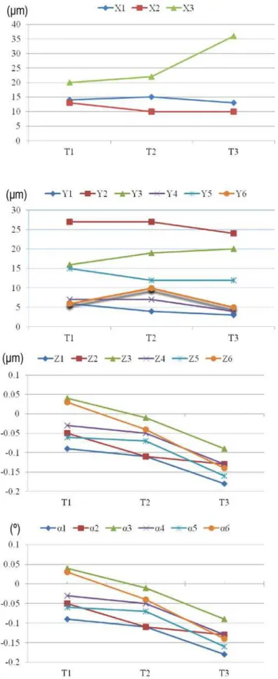
Analysis of variance with a 95% confidence interval showed that the type of tray did not have any significant in-fluence (p > 0.05) on the parameters of measurement, except for the X3 and α1-6. (p < 0.05) Therefore, with respect to α
1-6 and X3, the third tray yielded the results which were
significantly different from the first two trays. The presenta-tion and graphical comparison of the results are shown in Fi-gures 5 and 6.
Discussion
The results of this study show that both the experimental master model and the technique used for ma-king the dental impressions have proven to be a reliable met-hod for assessment of the accuracy of dental impression ma-terials. Working casts obtained from all the three custom trays were, in most cases, significantly different from the experimental master model. Most evident deviations were recorded in the sagittal (Y2) and transversal plane (X3) for all
of the working casts. These were also the greatest distances among the measured abutments, so the differences were most likely to be observed. The measurement of all of the working casts was done by the principles of 3D measurement. Each surface of the abutments was measured with 50–100 surface points. The coordinates of surface points served as a base for measuring the geometry of the abutments. Due to a large number of data and easier analysis of measurement, the re-sults were presented as a cross-section of the model in one plane, which in this case passed through the base of the abu-tments. This is why the results are presented as the classical 2D measurement, but the principles of measurement are rela-ted to the entire surface of the measured model and additio-nal data can be withdrawn for each additioadditio-nal cross-section 25.
The impression material used in this study had a defi-ned polymerization contraction of ≤ 0.2%, while expansion of gypsum was claimed to be 0.19% by the manufacturer. Expansion of gypsum would thus compensate for polymerization contraction of the impression material, but it should be noted that these values refer to the two sizes that are not equal, ie the thickness of the impression material in accordance with the height and width of the gypsum abut-ments 26. Thickness of the impression material varied from 1 to 3 mm from each side of the abutment, while the height and width of the abutments varied between 4.5 and 7.5 mm. In relation to this, expansion of gypsum should be a more dominant factor, which was proven by this study. Additionally, the influence of the micromechanical retention of the impression material to a custom tray should also be considered. In this case, the expansion of gypsum will be su-perimposed with the impression materials contraction towards the tray's walls, so that the combined effect will be presented by even wider abutments. As for the height of the abutments, where the upper surface was smaller than the side surface of the custom tray, in most cases the height of the abutments was smaller than that of the master model (Z1-6).
This can also be explained by impression materials contrac-tion towards the walls. As the side surface of the tray had a bigger contact area than the upper one, the impression mate-rial was pulled down, which resulted in shorter abutments. These results are in accordance with other studies where tray adhesive was used in their research protocols 27–29.
The previously described process indicates that the sili-cone addition had a good retention with a custom tray made of epoxy resin by the RP technique. Although the RP technique is not widely used in the field of dentistry, it shows promise for manufacturing of dental devices. Its use in
everyday practice, as a rational method for fabrication of custom trays, requires advanced systems for intra- or extraoral scanning, together with an adequate software con-nected to an RP machine, which is currently a limiting factor. Additive technologies such as RP are mainly being used for the production of dental copings for fixed dental restoration, fabrication of surgical guides in implant dentistry and in re-constructive maxillofacial surgery 30, 31. As there is a large variety of materials that can be used for the production of cu-stom trays with RP technology in different working regimes, these results are just a starting point and require additional investigation.
The analysis of convergence of axial surfaces showed that the largest deviations were observed in the third custom tray (α1 = -0.18°), while deviations of the second tray (α1, 2 =
-0.11°) and the first tray (α1 = -0.09°) were smaller. The angle
of convergence was measured by scanning the axial surface and further software processing. Although small, deviations detected were oriented towards the increase of convergence. Convergence of the axial wall of the master model abutments was set to 6° (total of 12° when observing both axial planes), while gypsum abutments were detected to have more of a ta-per. The increase of the convergence angle reduces the ove-rall surface of the abutment, which can influence the retenti-on of the dental restoratiretenti-on 32. While the width of the abut-ments was wider in the base cross-section, the axial surface has proven to have more taper. This could be explained by the increase of thickness of the impression material towards the upper base of the abutment and lower retention to the impression tray. Also, during removal of the impression the material deforms elastically. The resulting effect will be mo-re pronounced in the axial surface, because of the overall in-crease of contact surface and direction of removal force away from the base of the abutment. This may all together explain the behaviour of the material to contract towards the walls of the tray in the base area, while slightly contracting inwards as the height progresses.
Difficulty of comparison of our own results with other studi-es, lies in the complexity of the methodological procedure. Even comparison with studies that used the monophasic im-pression technique, as it was in this study, should be obser-ved not only by input, but also by output parameters, which are obtained through the use of the measurement instrument. As most of the studies used different measurement procedu-res, a relevant overview is hard to achieve, so we will restra-in from further data comparison.
Limitations of this study are related primarily to the met-hod of measurement. Although CMM is an instrument of great accuracy and precision, it is necessary to know the geometry of the measurement object in order to obtain reliable results 3. Because the measurement is done by a relatively small amount of surface points (in this study up to 100), the measurement object has to be clearly defined before the measurement takes place. Since the master model of known dimensions and shape was used, measuring in this study is characterized by conside-rable accuracy and precision.
Based on the obtained data, future studies would be ba-sed on determing of accuracy of the rest of the production process of dental restorations, including production of wax patterns and the casting procedure. Detection of flaws in each of the stages of the production procedure, will provide
useful guidelines for the dentists and dental technicians for the improvement of the quality of dental restorations.
Conclusion
The results of this study show that the impression ma-terial bulk of 1–3 mm could provide accurate working casts when using a monophasic impression technique. The incre-ase of the distance between abutment teeth influences the accuracy of working casts. Custom trays produced by rapid prototyping can be successfully used for dental impressi-ons. The experimental master model, combined with a CMM, is a reliable tool for assessment of dental impression accuracy.
Acknowledgements
The results presented in this paper were obtained in the framework of the project entitled “Research and develop-ment of modelling methods and approaches in manufacturing of dental recoveries with the application of modern techno-logies and computer aided systems” – TR 35020, financed by the Ministry of Education, Science and Technological Deve-lopment of the Republic of Serbia.
R E F E R E N C E S
1. Rosenstiel SF, Land MF, Fujimoto J. Contemporary fixed prost-hodontics. St. Louis: Mosby Inc; 2006.
2. Quaas S, Rudolph H, Luthardt RG. Direct mechanical data ac-quisition of dental impressions for the manufacturing of CAD/CAM restorations. J Dent 2007; 35(12): 903−8. 3. Ender A, Mehl A. Accuracy of complete-arch dental
impres-sions: a new method of measuring trueness and precision. J Prosthet Dent 2013; 109(2): 121−8.
4. Trifkovic B, Budak I, Todorovic A, Hodolic J, Puskar T, Jevremovic D, et al. Application of Replica Technique and SEM in Accuracy Measurement of Ceramic Crowns. Measur Sci Rev 2012; 12(3): 90−7.
5. Persson ASK, Odén A, Andersson M, Sandborgh-Englund G. Digiti-zation of simulated clinical dental impressions: virtual three-dimensional analysis of exactness. Dent Mater 2009; 25(7): 929−36.
6. Rodriguez JM, Bartlett DW. The dimensional stability of impres-sion materials and its effect on in vitro tooth wear studies. Dent Mater 2011; 27(3): 253−8.
7. Ceyhan JA, Johnson GH, Lepe X. The effect of tray selection, viscosity of impression material, and sequence of pour on the accuracy of dies made from dual-arch impressions. J Prosthet Dent 2003; 90(2): 143−9.
8. Caputi S, Varvara G. Dimensional accuracy of resultant casts made by a monophase, one-step and two-step, and a novel two-step putty/light-body impression technique: An in vitro study. J Prosthet Dent 2008; 99(4): 274−81.
9. Luthardt RG, Kühmstedt P, Walter MH. A new method for the computer-aided evaluation of three-dimensional changes in gypsum materials. Dent Mater 2003; 19(1): 19−24.
10.Brosky ME, Pesun IJ, Lowder PD, Delong R, Hodges JS. Laser dig-itization of casts to determine the effect of tray selection and cast formation technique on accuracy. J Prosthet Dent 2002; 87(2): 204−9.
11.Mishra S, Chowdhary R. Linear dimensional accuracy of a poly-vinyl siloxane of varying viscosities using different impression techniques. J Investig Clin Dent 2010; 1(1): 37−46.
12.Marković D, Puškar T, Hadžistević M, Potran M, Blažić L, Hodolič J. The dimensional stability of elastomeric dental impression materials. Contemp Mater 2012; 3(1): 105−10.
13.Poniatowska M. Parameters for CMM Contact Measurements of Free-Form Surfaces. Metrol Measur Sys 2011; 18(2): 199−208. 14.Nissan J, Gross M, Shifman A, Assif D. Effect of wash bulk on the accuracy of polyvinyl siloxane putty-wash impressions. J Oral Rehabil 2002; 29(4): 357−61.
15.Kumar V, Aeran H. Evaluation of Effect of Tray Space on the Accuracy of Condensation Silicone, Addition Silicone and Po-lyether Impression Materials: An In Vitro Study. J Indian Pros-thodont Soc 2012; 12(3): 154−60.
16.Hoyos A. Influence of tray rigidity and material thickness on accuracy of polyvinyl siloxane impressions [thesis]. Gainesville, FL: Graduate School of the University of Florida; 2006. 17.de Araujo PA, Jorgensen KD. Effect of material bulk and
under-cuts on the accuracy of impression materials. J Prosthet Dent 1985; 54(6): 791−4.
18. Rajapur A, Dixit S, Hoshing C, Raikar SP. The influence of tray space and repeat pours on the accuracy of monophasic polyvi-nylsiloxane impression. J Contemp Dent Pract 2012; 13(6): 824−9.
19.Mandikos MN. Polyvinyl siloxane impression materials: an up-date on clinical use. Aust Dent J 1998; 43(6): 428−34. 20.Fehling AW, Hesby RA, Pelleu GB. Dimensional stability of
au-topolymerizing acrylic resin impression trays. J Prosthet Dent 1986; 55(5): 592−7.
21.Sched RC, Weiss G. Woelfel's dental anatomy. Philadelphia: Lippincott Williams&Wilkins; 2012. p. 41.
verifi-cation. Geneva: International Organization for Standardiza-tion; 2002.
23.Weckenmann A, Knauer M, Kunzmann H. The Influence of Mea-surement Strategy on the Uncertainty of CMM-MeaMea-surements. CIRP Annal Manufac Technol 1998; 47(1): 451−4.
24.Wilhelm RG, Hocken R, Schwenke H. Task Specific Uncertainty in Coordinate Measurement. CIRP Annal Manufac Technol 2001; 50(2): 553−63.
25.Chandran DT, Jagger DC, Jagger RG, Barbour ME. Two- and three-dimensional accuracy of dental impression materials: ef-fects of storage time and moisture contamination. Biomed Ma-ter Eng 2010; 20(5): 243−9.
26.de Long R, Heinzen M, Hodges JS, Ko CC, Douglas WH. Accuracy of a system for creating 3D computer models of dental arches. J Dent Res 2003; 82(6): 438−42.
27.Boulton JL, Gage JP, Vincent PF, Basford KE. A laboratory study of dimensional changes for three elastomeric impression mate-rials using custom and stock trays. Aust Dent J 1996; 41(6): 398−404.
28.Johnson GH, Craig RG. Accuracy of four types of rubber im-pression materials compared with time of pour and a repeat pour of models. J Prosthet Dent 1985; 53(4): 484−90. 29.Lewinstein I. The ratio between vertical and horizontal changes
of impressions. J Oral Rehabil 1993; 20(1): 107−14.
30.Jevremovic DP, Puskar TM, Budak I, Vukelic DJ, Kojic V, Eggbeer D, et al. An RE/RM approach to the design and manufacture of removable partial dentures with a biocompatibility analysis of the f75 Co-Cr-Slm alloy. Mat Technol 2012; 46(2): 123−9. 31.Wu M, Tinschert J, Augthun M, Wagner I, Schädlich-Stubenrauch J,
Sahm PR, et al. Application of laser measuring, numerical simu-lation and rapid prototyping to titanium dental castings. Dent Mat 2001;7(2):02−8.
32.Chan DC, Chan BH, Chung AK. Mathematical modeling of mo-lar tooth preparations for complete crowns. J Dent 2007; 35(11): 875−7.
33.Schaefer O, Schmidt M, Goebel R, Kuepper H. Qualitative and quantitative three-dimensional accuracy of a single tooth cap-tured by elastomeric impression materials: An in vitro study. J Prosthet Dent 2012; 108(3): 165−72.
34.Tjan AH, Nemetz H, Nguyen LTP, Contino R. Effect of tray space on the accuracy of monophasic polyvinylsiloxane im-pressions. J Prosthet Dent 1992;8(1): 19−28.
35.Eames WB, Sieweke JC, Wallace SW, Rogers LB. Elastomeric im-pression materials: effect of bulk on accuracy. J Prosthet Dent 1979; 41(3): 304−7.