AUTOMATIC RECOVERING NODE
FAILURE IN WIRELESS SENSOR
ACTOR NETWORKS
C.A.Subasini1, Dr. Chandra Sekar A 2
1
Research Scholar, Manonmaniam Sundaranar University, Tirunelveli, Tamilnadu, India & Associate Professor, Department of MCA, St.Joseph’s College of Engineering, Chennai, India,
2
Professor, Department of CSE, St.Joseph’s College of Engineering, Chennai, India.
Abstract- Automatic recovering node failure in wireless sensor actor network to identify the cutvertex and to meet to the node failure. The network consists of many nodes that are constructed into a tree structure. Once the tree has been constructed the shortest path is found by the Aodv protocol.If a node failure occurs in the shortest path then the cut-vertex could be recovered and the data can be securely passed on to the destination in an alternative route obtained from the routing table. Heartbeat messages acknowledge the node failure. The feasible path is not found by the protocol, and then the network is divided into two or many parts. The MLeDir algorithm is used to identify the network failure and disjoint block of the network. The disjoint block is identified by the MLeDir algorithm and to rectify the disjoint block of failure network nodes. MLeDir algorithm is moving only the respective nodes from source to destination.
Keywords: MLeDir,LeDir,DARA,PADRA
I. Introduction
In the recent years there has been an increase in the wireless applications. Areas in which human intervention is risky or impractical these wireless applications have been of great help in intervention of such places. [1]A Wireless Sensor Actor Network consists of a set of miniaturized low-cost sensors that are spread in an area of interest to measure ambient conditions in the vicinity. The sensors serve as wireless data acquisition devices for the more powerful actor nodes that process the sensor readings and put forward an appropriate response. The actors are the main part of the network. Actors work autonomously and collaboratively to achieve the application mission.
For the purpose of achieving the mission the actor nodes are to be connected strongly forming an inter-connected network topology. Actors usually coordinate their motion so that they stay reachable to each other. However, a failure of an actor may cause the network to partition into disjoint blocks and would thus violate such a connectivity requirement. The remote setup in which WSANs often serve makes the deployment of additional resources to replace failed actors impractical and repositioning of nodes becomes the best recovery option. On the other hand the node failure cannot be tolerated as this would cause data loss which cannot be met. The repositioning of the nodes in the network is not an easy or simple task that could be completed as this would case disturbance to the whole network.
Replacing the failure node is also not easy as the node replacement requires time and this would cause a delay in the data transfer. Delay in the data transfer is not tolerable. Replacing the failure node is also not cost efficient. For this purpose an alternate method is used for meeting the node failure and for the purpose of data
transfer. All the actor nodes in the network are scattered separately from each other. The scattered nodes are constructed into a tree structure based on the energy of the nodes. Once the tree has been constructed the shortest path is found by AODV protocol and maintained as a routing table. When the shortest path is noted then the data is transferred in the shortest path to the destination.
If a node failure occurs in the shortest path then the node failure can be recovered and the data can be securely passed on to the destination in an alternative route obtained from the routing table. The details of all the routes and the shortest path based on the hop count in the network are maintained as a routing table which provides the required information about of all the available routes.
In order to prevent from data loss and for the successful delivery of the data from source to destination a new method for secure data transfer is used. The method does the work of finding the shortest path and data transfer and if node failure occurs the data is transferred in an alternate route, if alternate path is not found then the network is divided into disjoint block. Recovery process is done using modification of the LeDir algorithm. By using the recovery process data is successfully transferred from the source to destination.
This paper is organized as follows: the second section shows a brief review of some related researches and the third section shows the system architecture and the fourth section explains our recommended system and the sixth section concludes our recommended technique.
II. Related Research: a Brief Review
This section shows some of the recent related researches about actor networks. Ameer et al. [12] proposed the new distributed node recovery algorithms (DARA 1C,DARA 2C) to restore the connectivity of the partitioned inter-actor network. The idea of DARAs is the use of the least number of actor nodes in order to establish the lost connectivity
between disjoint networks. DARAs have four main drawbacks as claimed by Akkaya et al.[12]: (i) DARAs do not provide any mechanism to detect the cut-vertices. It is assumed that this information is available with each node which may require the complete knowledge of whole topology (i.e. implicit centralized in nature), (ii) the selection of the FHs to replace the failed node is done based on the neighbors’ degree which may require sometimes excessive replacement of nodes until a leaf node is found, thereby increasing maximum movement distance of all individual actors (MMI), which will consume more energy of the network,(iii) the best candidate selection is done reactively using a lot of calculation, which is verycritical for delay sensitive applications, (iv) the major problem occurs with cyclic network.
Akkaya et al. [6,7] presented the new distributed partition detection and recovery algorithm (PADRA, PADRA+) to handle the connectivity problem through detection of possible partitions after the failure of the cut-vertex node is observed in the network and restores the network connectivity through controlled relocation of the movable nodes. The idea is the identification of nodes in advance that will cause partitioning in the network. PADRA has three main drawbacks: (i) like DARAs, PADRA does not provide any mechanism to detect the cut-vertices and non-cut vertices in the network, (ii) selection of the FH to replace the failed node is done based on the neighbor’s node distance which may requires excessive replacement until a leaf node hits, (iii) communication overhead is large due to unnecessary cut-vertices assumed in PADRA. The authors have also proposed second distributed algorithm PADRA+ to further reduce the travelling distance of involved nodes with the cost of message overhead. The only difference between PADRA and PADRA+ is that PADRA+ calculates cut vertex and non-cut vertex prior to failure using dynamic programming (DP). Unlike the assumption in PADRA, PADRA+ assumes all non-leaf nodes are cut-vertex. It also helps to reduce the problem encountered in the cyclic network topologies. Abdullah et al. [13] proposed a distributed algorithm called least distance movement recovery (LDMR) approach which exploits non-cut-vertex nodes for the recovery so that no further partitioning occurs after the movement of the involved nodes. The idea is to move the direct neighbor nodes to the failed node position while its original position is replaced with the nearest non-cut-vertices. LDMR uses node mobility and availability of non-cut-vertices for the network recovery during the recovery process. LDMRhas two main drawbacks: (i)Due to searching of non-vertex nodes at the time of the recovery, a large computation overhead occurs on each node which consumes more energy, consequently decreases the network lifetime, (ii) every node searches the non-vertex node by sending the search message therefore, a flood like situation appears in the network and consequently congestion occurs in the network, (iii) the node status is not considered during partitioned recovery.
Imran et al. [10] presented novel distributed algorithm partitioning detection and connectivity restoration (PCR) Algorithm to repair connectivity while imposing minimal communication overhead on each node during the recovery process. The idea presumed by the authors is to pursue node relocation in order to restructure the topology and regain the strong connectivity. In addition, PCR tackles the problem of increased interference when many neighbor nodes move to the vicinity of the failed node for the recovery. PCR has mainly two drawbacks: (i) a large number of nodes are required for partitioned recovery, (ii) convergence of the algorithm is not mentioned. Ameer et al. [12] presented least disruptive topology repair algorithm (LeDiR) to recover the partitioned connectivity through relocating a complete smallest block of nodes among the disjoint partitions and ensure that no path get extended between the pair of nodes as compared to the pre-failure condition. LeDiR has three main drawbacks: (i) all the nodes of a block are moved for the recovery and it causes a large number of nodes movement in the network, (ii) the significant amount of energy is consumed by large participated nodes for the recovery, (iii) the smallest block calculation is done on-the-fly at the time of the recovery
inward motion (RIM) for the network partition recovery. The main idea is to move the entire neighbor node(s) towards inward direction of the failed node so that nodes can discover each other and recovery can take place. RIM reduces the message overhead by maintaining only 1-hop neighbor information. RIM has three main drawbacks: (i) a large number of relocated nodes are required for the recovery, (ii) large network topology is changed during recovery, (iii) no coverage issue along with connectivity is considered in this approach. Zamanifar et al. [9] proposed an efficient proactive distributed approach called actor on mobility (AOM) to restore the connectivity. The idea is to find the critical nodes in advance for the partition recovery. AOM has two main drawbacks: (i) no termination point of the algorithm is given, (ii) no procedure is described to find suitable FHs. Zhao and Wang [21] proposed a new distributed scheme called coordination-assisted connectivity recovery approach (CCRA) to handle the network partitioning problem with least number of the nodes. The idea is to calculate node status i.e. cut-vertex or non-cutvertex node at the time of its failure to reduce the pre-failure computation overhead on the network. CCRA has two main drawbacks: (i) a large communication overhead occurs during the recovery, which is not suitable for the energy efficient applications, (ii) no coverage issue along with connectivity is taken, (iii) due to implicit centralized in nature, a scalability problem exists. Akkaya and Younis [4] is to maximize the coverage of the actor nodes while maintaining connected topology. The main problem in C2AP is that it requires a large number of actor nodes in the recovery process to restore the lost connectivity.
III. WSANs Sytem architecture
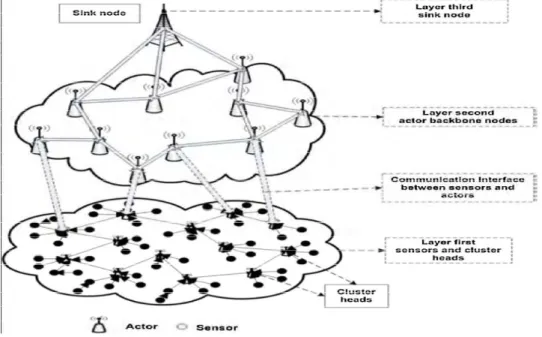
This section explains the WSANS sytem architecture. In Fig.1 shows Wireless sensor and actor networks (WSANs) are characterized by dense deployment of energy constrained sensor nodes with small number of the backbone actor nodes
Fig. 1 An articulation of layered architecture of WSANs
IV.PROPOSED MLeDir
This section explains our proposed network consists of many nodes that are scattered in the network separated from each other. The scattered nodes are constructed into a tree structure. Once the tree has been constructed the shortest path is found by the Aodv protocol. MLeDir algorithm to identify the cut vertex and to meet to the node failure. The actor nodes are made aware of all the nodes that are available in the network initially.
IV.1 Construction of Tree Topology
Tree Topology is a combination of the bus and the Star Topology. The tree like structure allows you to have many servers on the network and you can branch out the network in many ways. A Tree Topology is supported by many network vendors and even hardware vendors.
A Tree Structure suits best when the network is widely spread and vastly divided into many branches. Like any other topologies, the Tree Topology has its advantages and disadvantages. A Tree Network may not suit small networks and it may be a waste of cable to use it for small networks. Tree Topology has some limitations and the configuration should suit those limitations. A point to point connection is possible with Tree Networks. All the computers have access to the larger and their immediate networks. Best topology for branched out networks. In a Network Topology the length of the network depends on the type of cable that is being used.
The Tree Topology network is entirely dependent on the trunk which is the main backbone of the network. If that has to fail then the entire network would fail. Since the Tree Topology network is big it is difficult to configure and can get complicated after a certain point. The Tree Topology follows a hierarchical pattern where each level is connected to the next higher level in a symmetrical pattern. Each level in the hierarchy follows a certain pattern in connecting the nodes. Like the top most level might have only one node or two nodes and the following level in the hierarchy might have few more nodes which work on the point to point connectivity and the third level also has asymmetrical node to node pattern and each of these levels are connected to the root level in the hierarchy. Think of a tree that branches out in various directions and all these branches need the roots and the tree trunk to survive. A Tree Structured network is very similar to this and that is why it is called the Tree Topology.
Tree Topology Features are as follows. There will be at least three levels of hierarchy in the Tree Network Topology and they all work based on the root node. The Tree Topology has two kinds of topology integral in it, the star and the linear way of connecting to nodes. The Tree Topology functions by taking into account the total number of nodes present in the network. It does not matter how many nodes are there on each level. Nodes can be added to any level of the hierarchy and there are no limitations a far as the total number of nodes do not exceed.
The signals that are being transmitted by the root node are received by all the nodes at the same time. This increases the efficiency of the overall functioning of the network. The Tree Network topology can be extended easily to function and there are no limitations to how big it can be extended. Additional root nodes can be added and they can be interconnected within one single network.
Each and every network consists of many number of actor nodes. The actor nodes are very important as they are the ones that help in data transfer between the nodes. Nodes can be added to any level of the hierarchy and there are no limitations a far as the total number of nodes do not exceed. The networks consist of many nodes that are scattered in the network separated from each other.
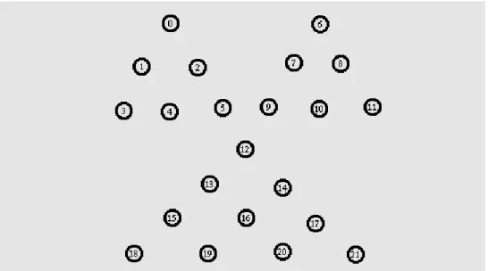
Fig.2. Node Tree construction
In Fig.2 shows the actor nodes that are present in the network. The actor nodes are constructed in tree topology. 1.Define the simulation parameters in the beginning of the program
TABLEI Simulation Parameters
Chan(channel type) Channel/Wireless Channel
Prop (radio-propagation model ) /TwoRayGround
ant (Antenna type) Antenna/OmniAntenna
Ll (Link layer type ) LL
Ifq (Interfacequeuetype) Queue/DropTail/PriQueue
Ifqlen (max packet in ifq) 50
Netif (network interface type ) Phy/WirelessPhy
Mac (MAC type ) Mac/802_11
adhocRouting(ad-hoc routing protocol) AODV
nn (mobilenodes) 100
Mobility Hybrid Random walk
Propagation models are used to predict the received signal power of each packet. At the physical layer of each wireless node, there is a receiving threshold. When a packet is received, if its signal power is below the receiving threshold, it is marked as error and dropped by the MAC layer. The multicast classifier classifies packets according to both source and destination (group) addresses. It maintains a (chained hash) table mapping source/group pairs to slot numbers. When a packet arrives containing a source/group unknown to the classifies.
2. Set up topography object for the topology creation.
set topo [new Topography] ;# Create a Topography object
$topoload_flatgrid 1000 1000
TABLE2 Node Parameters
-llType LL
-ifqType "Queue/DropTail/PriQueue" -ifqLen 50
-macType Mac/802 11 -phyType "Phy/WirelessPhy“ -adhocRouting AODV
-antType "Antenna/OmniAntenna“ -channelType "Channel/WirelessChannel“
The base class Queue, from which Drop Tail is derived, provides most of the needed functionality. The drop-tail queue maintains exactly one FIFO queue, implemented by including an object of the PacketQueue class.
4. Then set a tcp connection between n(1) and n(2) and connect the nodes by function called connect i.e connection of tcp agents source and sink.
5. Defining node initial position in nam ( network animator) which displays the mobile nodes in the network.
6. Starting time of simulation and ending time of the simulation will be defined in this step.
7. Finally network is created.
IV.2 Identification of Fault Node
Once the node tree has been formed the shortest path is found by the Aodv protocol. All the node information’s are maintained by the routing table. The routing table consists of
(1) All available path between the source and destination.
(2) Number of all possible hop count between all the nodes.
Actors will periodically send heartbeat messages to their neighbors to ensure they are functional and also report changes to the 1-hop neighbors. Missing heartbeat messages can be used to detect the failure of actors. Once a failure is detected in the neighborhood, the 1-hop neighbors of the failed actor would determine the impact, i.e., whether the failed node is critical to the network connectivity. Fault node is identified by the source node. Fault node does not forward data to next node, it drops the packet. During node failure the Aodv finds the alternate path periodically.
The smallest block is the one with the least number of nodes and would be identified by finding the reachable set of nodes for every direct neighbor of the failed node and then picking the set with the fewest nodes.
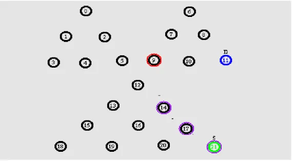
Fig. 3 Shortest path identification and data transfer
IV.3 Replacing fault node
Once the nodes have been rearrange into tree structure, the shortest path is identified from the routing table and the data is passed in the shortest path. When the data is passed in the shortest path if a node failure occurs in the path, it is identified using the acknowledgment message, and then the data transfer is stopped. Then the next feasible path is identified based on the hop count from the routing table. When the new feasible path is identified then the data is send to the destination.
The Routing table contains relay nodes of source to destination. If the node failure occurs then the routing path to be changed from routing table, the routing path is not found by the source then the network is not reachable to the destination. If the path is not found by the source then the network divided into two or more blocks. The modification of MLeDir algorithm is used to recover the node failure of disjoint block of nodes. The algorithm is used moving the respective nodes from source to destination, no need of moving the entire disjoint block nodes.
MLeDiR limits the relocation to nodes in the smallest disjoint block in order to reduce the recovery overhead. The smallest block is the one with the least number of nodes and would be identified by finding the reachable set of nodes for every direct neighbor of the failed node and then picking the set with the fewest nodes. Since a critical node will be on the shortest path of two nodes inseparate blocks, the set of reachable nodes can be identified through the use of the SRT after excluding the failed node.
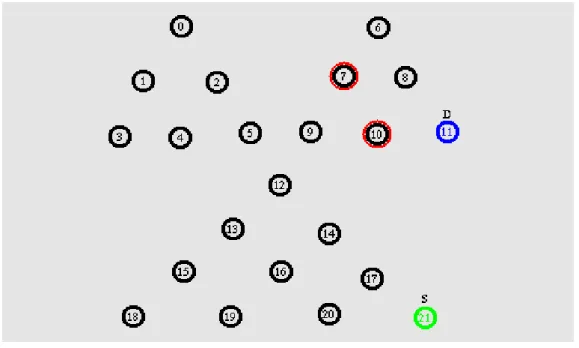
Fig. 4 Node Failure
In Fig.4 shows the identification of the cut vertex and small block nodes identified in the path of the data transfer from the source to destination. Red color node shows identification of failure node
IV.4 MLeDir Algorithm
Algorithm for our proposed technique:
Step 1: (Identification of failure node)
IF node J detects a failure of its neighbor F Choose another routing path from routing table.
Heartbeat message send to the source. ELSE
Find routing path and Forward data to the destination ENDIF
Step 2: (Identification of disjoint block) IF neighbor F is a critical node
Notify_Children(J);
J moves to the Position of neighbor F; END IF
Step 3: (Children movement)
IF J receives (a) notification message(s) from F NewPosition =Compute_newPosition(J);
IF NewPosition != CurrentPosition(J) Notify_Children(J);
Respective Children nodes are moved to NewPosition; END IF
END IF
Step 4: (Identification of alternate path after node movement) // Check whether J is the best node for tolerating the failure NeighborList[] = GetNeighbors (F) by accessing column F in SRT;
SmallestBlockSize = Number of nodes in the network; FOR each node i in the NeighborList[]
//Use the SRT after excluding the failed node to find the set of reachable nodes;
Number of reachable nodes = 0; FOR each node k in SRT excluding i and F Retrieve shortest path from i to k by using SRT; IF the retrieved shortest path does not include node F No. of reachable nodes = No. of reachable nodes + 1;
END IF END FOR
IF Number of reachable nodes < SmallestBlockSize SmallestBlockSize = Number of reachable nodes;
END IF END FOR
V. Result and Discussion
This section delineates the results we obtained for our recommended technique. This section contains the experimental setup and dataset description, comparative analysis of our recommended technique with the existing technique.
V.1 Experimental setup
In the experiment the network was constructed with 22 nodes and rearranged in a tree structure and the data was transferred in the shortest path. In the case of node failure the data was passed in an alternate route. From this experiment we found that the proposed system was efficient in the case of node failure identification, minimize the node movement and selection of alternate route than the existing system.
V.2 Comparative Analysis
To implement the proposed system NS2 was used and using the NAM animator the system was simulated and all the modules of the proposed system were implemented. The system was run for various values of data, energy and path.
In case of the node failure the data loss was prevented by passing the data to the destination in an alternate shortest path. In case the alternate path was not found failure node neighbours moved to failure node and then data was successfully transferred.
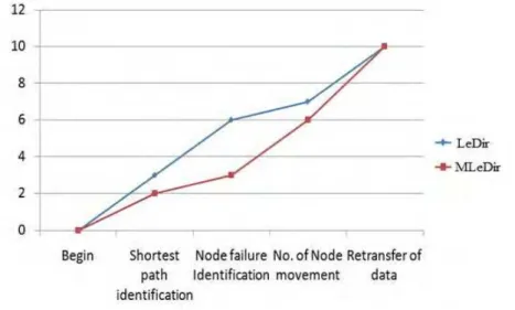
Fig. 5 Performance analysis based on Retransfer of data.
In Fig.5 gives details of the difference between the proposed system and the existing system. The existing takes time in identifying the shortest path from the source to destination as the nodes in the network are scattered and are not aware of the neighbour.
This problem is eliminated in the proposed system where the nodes that are scattered are arranged in a tree structure by doing so the nodes are aware of the neighbors and shortest path is easily identified.
The node failure is easily identified in the proposed system by making use of the acknowledgement that is delivered from the node that receives the data from the source. Once the cut vertex is identified the existing system takes time to find the identification of the shortest network as the whole network is to be traversed again in order to find the shortest network and takes relocation of the smallest network for recovering node failure.
The proposed system does not relocate the smallest network instead identifies alternate route and transfers data in that path. This time is saved in the proposed system where the details about all the available path is noted down in the routing table initially, so when a node failure occurs the data is immediately passed in an alternate route. Thus from the experiments conducted the proposed system has proved to work effectively then the existing system.
VI. Conclusion
In this paper we have recommended MLeDiR can recover from a single node failure at a time. Generally, simultaneous node failures are very improbable unless a part of the deployment area becomes subject to a major hazardous event, considering such a probl em with collocated node failure is more complex and challenging in nature. In future, we plan to investigate this issue. Our future plan also includes factoring in coverage and on-going application tasks in the recovery process and developing a test-bed for evaluating the various failure recovery schemes. The performance of MLeDiR has been validated through rigorous analysis and extensive simulation experiments. The experiments have also compared MLeDiR to a centralized version and to contemporary solutions in the literature.
All the nodes in the path in which the data is passed to verify continuously by the use of ack and if the ack is not received then the node is considered to be failed. This node is considered as cut vertex. Then the data is transferred in the next feasible path. As a result the new system provides technique for the purpose of successful data transfer.
References
[1] Younis, M., & Akkaya, K. (2008). Strategies and techniques for node placement in wireless sensor networks: A survey. Ad-Hoc Networks, 6(4), 621–655.
[2] Ameer, A. A., Younis, M., & Akkaya, K. (2009).Movement- assisted connectivity restoration inWSANs. IEEE Transactions on Parallel and Distributed Systems, 20(9), 1366–1379. for tolerating node failures in WSNs: A survey. Computer Networks, 1–30. [3] Wang, G., Cao, G., & La Porta, F. T. (2006). Movement-assisted sensor deployment. IEEE Transactions on Mobile Computing, 5(6),
[4] Akkaya, K., & Younis, M. (2007). Coverage-aware and onnectivity constrained actor positioning in WSANs. In Proceedings of 26th IEEE international conference on performance computing and communications conference (IPCCC’07) (pp. 281– 288), New Orleans, LA, USA.
[5] Ameer, A. A., Akkaya, K., & Younis, M. (2007). A distributed connectivity restoration algorithm in WSANs. In Proceedings of 32nd IEEE conference on local computer networks (pp. 496–502), Dublin
[6] Akkaya, K., Thimmapuram, A., Senel, F., & Uludag, S. (2008). Distributed recovery of actor failures in WSANs. In Proceedings of IEEE wireless communications and networking conference (WCNC’08) (pp. 2480–2485), Las Vegas, NV.
[7] Akkaya, K., Senel, F., Thimmapuram, A., & Uludag, S. (2010). Distributed recovery from network partitioning in movable sensor/actor networks via controlled mobility. IEEE Transactions on Computers, 59(2), 1669–1682.
[8] Younis, M., Lee, S., Gupta, S., & Fisher, K. (2008). A localized self-healing algorithm for networks of moveable sensor nodes. In Proceedings of IEEE international conference on global communications (Globecom’08) (pp. 1–5), New Orleans, LA, USA.
[9] Zamanifar, A., Kashefi, O., & Sharif, M. (2009). AOM: An efficient approach to actor–actor connectivity restoration inWSANs. International Journal of Computer Networks and Communications (IJCNC), 1(1),61–72.
[10] Imran, M.,Younis, M., Said A. M.,&Hasbullah,H. (2010). Partitioning detection and connectivity restoration (PCR) algorithm for wireless sensor actor networks. In Proceedings of IEEE/IFIP 8th international conference on embedded and ubiquitous computing (EUC’10) (pp. 200–207), Hong Kong, SAR.
[11] Ameer,A. A.,Younis, M.,&Baroudi,U. (2010). Restoring connectivity in wireless sensor-actor networks with minimal topology changes. In Proceedings of IEEE international conference on communications (ICC’10) (pp. 1–5), Cape Town, South Africa.
[12] Ameer,A. A.,Younis, M.,&Baroudi,U. (2011).Restoring connectivity in wireless sensor–actor networks with minimal node movement. In Proceedings of 7th international wireless communications and mobile computing conference (IWCMC’11) (pp. 2046–2051), Istanbul, Turkey.
[13] Abdullah, A., Baroudi, U., & Younis, M. (2011). Least distance movement recovery approach for large scale wireless sensor and actor networks. In Proceedings of 7th international wireless communications and mobile computing conference (IWCMC’11) (pp. 2058– 2063), Istanbul, Turkey.
[14] Sir, M., Senturk, I., Sisikoglu, F., & Akkaya, K. (2011). An optimization-based approach for connecting partitioned mobile sensor/actuator networks. In Proceedings of 3rd international workshop on wireless sensor, actuator and robot networks (WiSARN), in conjunction with (IEEE INFOCOM’11) (pp. 525–530), Shanghai, China.
[15] Joshi, Y. K., & Younis, M. (2012). Autonomous recovery from multi-node failures in wireless sensor networks. In Proceedings of IEEE global communications (GLOBECOM’12) (pp. 652–657), Anaheim, CA.
[16] Wang, G., Cao, G., & La Porta, F. T. (2006). Movement-assisted sensor deployment. IEEE Transactions on Mobile Computing, 5(6), 640–652.
[17] Senel, F., Akkaya, K., & Younis, M. (2007). An efficient mechanism for establishing connectivity in wireless sensor and actor networks. In Proceedings of IEEE global communications (Globecom’07) (pp. 1129–1133), St Louis, MO.
[18] Basu, P., & Redi, J. (2004). Movement control algorithms for realization of fault-tolerant adhoc robot networks. IEEE Network, 18(4), 36–44.
[19] Younis, M., Sentruk, I. F., Akkaya, K., Lee, S., & Senel, F. (2013). Topology management techniques for tolerating node failures in WSNs: A survey. Computer Networks, 1–30. [20] Basu, P., & Redi, J. (2004). Movement control algorithms for realization of fault-tolerant adhoc robot networks. IEEE Network, 18(4), 36–44.
[20] Zhao, X., & Wang, N. (2011). Coordination-assisted connectivity recovery approach in wireless sensor and actor networks. In |it Proceedings of 3rd IEEE international conference on computer research and development (ICCRD’11) (pp. 82–86), Shanghai, China
Authors
C.A.Subasini, received MCA degree from Annai Velankanni College affiliated to Manonmanium Sundaranar University, Tirunelveli, India. M.E(CSE) degree from Sathyabama University, Chennai, India and Pursuing Ph.D in Computer science &Engineering in Manonmanium Sundaranar University, Tirunelveli, India.He is currently working as an Associate Professor in the Department of MCA in St.Joseph’s College of Engineering, Chennai. Her research area is Wireless sensor Actor Networks.