Implementing Smart Antenna System in Mobile Ad Hoc
Networks
Supriya Kulkarni P
1, Bhavani V
2Student Electronics & Communication Dept MVJ College of Engineering Bangalore, India
Assistant Professor Electronics & Communication Dept MVJ College of Engineering Bangalore, India
Abstract
As the necessity of exchanging and sharing data increases, users demand easy connectivity, and fast networks whether they are at work, at home, or on the move. Nowadays, users are interested in interconnecting all their personal electronic devices (PEDs) in an ad hoc fashion on the move. This type of network is referred to as Mobile Ad hoc NETwork (MANET). When in such network a smart antenna System (SAS) is implemented then we can achieve maximum capacity and improve the quality and coverage. So we are intended to implement such a SAS in the MANET. In this paper we have shown significance of Throughput and Bit Error Rate by implementing SAS in MANET using MATLABR2010a.
Keywords
: Smart Antenna System (SAS), Mobile Ad hoc Network (MANET), Constant modulus algorithm (CMA), nodes, direction of arrival (DOA).I.
INTRODUCTION
The earliest of MANETs were called “packet -radio” networks, first sponsored by the United States (U.S.) Defense Advanced Research Projects Agency (DARPA) in the early 1970s. It is interesting to note that some early packet-radio systems predated the Internet and, indeed, were part of the motivation of the original Internet protocol (IP) suite. Later DARPA experiments included the Survivable Radio Network (SURAN) project, which took place in the 1980s. The third wave of academic activity on Wireless Ad-Hoc Networks started in the 1990s, especially with the wide usage of inexpensive 802.11 radio cards for personal computers [1].
Mobile Ad-hoc NETwork (MANET) is a selfconfigurable,Infrastructure less, autonomous and selfhealing system of nodes using wireless links. MANETs fall into the category of wireless networks inwhich each device can act as a source, destination and a moving router and can communicates with other devices in its range. Wherever there is no infrastructure or it is expensive to deploy a network easily, under such conditions MANET’s are very helpful.
Some of the applications of MANETs are military, industry, research, etc.
Mobile ad hoc networks (MANETs) can also be defined as the set of stations (nodes) communicating through wireless channels, without any fixed backbone support. Applications of MANETs are not just limited to, military operations, security, emergency, and rescue operations; they are used in environment which offers very limited availability of network topology and time.
The evolution of technology and the tendency of systems to become more software-dependent make computing environments and networks more complicated and less humanly controlled. In this paper, we consider the organizing a set of mobile nodes, that communicate through a wireless medium, into a connected network, in order to obtain a self-configuring or self-organizing network like MANET. We discuss these concepts and present a brief about self-configuring or self-healing algorithms, respectively, for wireless mobile networks. We detail a representative algorithms used in practice. We then go on to address the current theoretical results on self-configuring networks in section III.
II.
LITERATURE SURVEY
A. Mobile Ad hoc Network (MANET)
The capacity of ad hoc networks can be severely limited due to interference constraints. One way of using improving the overall capacity of ad hoc networks is by the use of smart antennas. Smart antennas allow the energy to be transmitted or received in a particular direction as opposed to disseminating energy in all directions. This helps in achieving significant spatial re-use and thereby increasing the capacity of the network. Typically these antennas are deployed at base-stations in these networks to sectorize cells and focus transmissions in certain directions.
A MANET consists of a collection of wireless mobile stations (nodes) forming a dynamic network whose topology changes continuously and randomly, and its intermodal connectivities are managed without the aid of any centralized administration. In contrast, cellular networks are managed by a
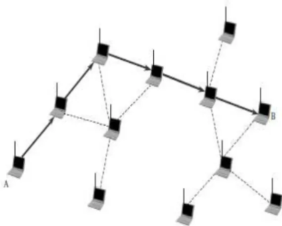
B, that desire to exchange data and are at some distance apart. Because they are out of radio range with each other, it is necessary for Node A to use the neighbouring or intermediate nodes in forwarding its data packets to Node B. In other words, the data packets from Node A are passed onto the neighbouring nodes in a series of single hops until the data packets reach Node B. This type of interaction among nodes is referred to as peer to peer and follows a set of rules for communication, referred to as protocol. Because the responsibilities of organizing and controlling this network are distributed among the nodes, efficient routing protocols must operate in a distributed manner and must be topology independent.
Fig. 1 Multihop Example of MANET.
The ability of smart antennas to direct their radiation energy toward the direction of the intended node while suppressing interference can significantly increase the network capacity compared to a network equipped with omnidirectional antennas because they allow the communication channel to be reused. In other words, nodes with omnidirectional antennas keep the neighbouring nodes on standby during their transmission while nodes with smart antennas focus only on the desired nodes and allow the neighbouring nodes to communicate (refer to Fig. 2). Therefore, smart antennas together with efficient access protocols can provide high capacity as well as robustness and reliability to mobile ad hoc networks.
Fig. 2. Capacity comparison of a network employing omnidirectional antennas and a network with smart
antennas.
B. Routing protocol
Efficient, dynamic routing is one of the key challenges in mobile ad hoc networks. Because, due to the frequent updates for changes in topologies, and active routes may be disconnected as mobile nodes move from one place to another. Routing protocols can be classified into: Source-initiated (reactive or on-demand), Table-driven (proactive), Hybrid, Location-aware (geographical), Multipath routing. Generally, in traditional MANETs, the nodes are addressed only with their IP addresses. But, in case of location-aware routing mechanisms, the nodes are often aware of their exact physical locations in the three-dimensional world.
Location-aware routing schemes in MANETs assume that the individual nodes are aware of the locations of all the nodes within the network. These are also called as Position-Based Routing. The best and easiest technique is the use of the Global Positioning System (GPS) to determine exact coordinates of these nodes in any geographical location. This location information is then utilized by the routing protocol to determine the routes. There are two methods of forwarding data packets in position based routing: greedy forwarding and directional flooding. In greedy forwarding, the next hop node is the closest in distance to destination. Greedy PerimeterStateless Routing Protocol (GPSR) uses the greedy forwarding. In the directional flooding, the source node floods data packets in a geographical area towards the direction of the destination node. Location Aided Routing (LAR) uses directional forwarding flooding.
�= 2− 1 2+ 2− 1 2 (1)
�= tan−1 2− 1
Fig. 3: Position-based routing protocol that uses GPS to determine mobile nodes (x, y) positions.
In the position-based routing protocols, node uses a directional antenna or GPS system to estimate its (x, y) position. If GPS is used, every node knows it's (x, y) position assuming z = 0. Fig. 3 shows two mobile nodes with their positions determined using GPS. The positions of the two mobile nodes in Fig. 1 are (x1, y1) and (x2, y2) respectively. Using Fig. 1, the distance d between the two mobile nodes is calculated using (1). The angle θ is defined as shown in Fig. 3 and is calculated using (2).
C. Smart antenna system
SAS is a subsystem that contains multiple antennas; based on the spatial diversity and signal processing, it significantly increases the performance of wireless communication systems as shown in Fig. 3. Many refer to smart antenna systems as smart antennas, but in reality antennas by themselves are not smart. It is the digital signal processing capability, along with the antennas, which make the system smart.
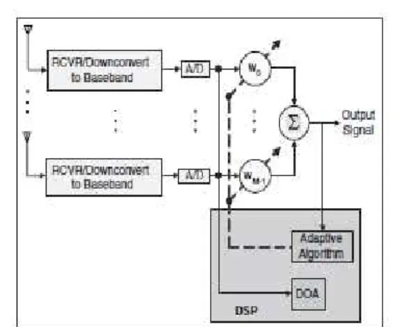
A functional block diagram of the digital signal processing part of an adaptive array antenna system is shown in Fig. 4. After the system downconverts the received signals to baseband and digitizes them, it locates the SOI using the direction-of-arrival (DOA) algorithm, and it continuously tracks the SOI and SNOIs by dynamically changing the complex weights (amplitudes and phases of the antenna elements).
The DOA computes the direction-of-arrival of all the signals by computing the time delays between the antenna elements, and afterward, the adaptive algorithm, using a cost function, computes the appropriate weights that result in an optimum radiation pattern.
The adaptive algorithm for beamforming is, Constant Modulus Algorithm (CMA), a gradient algorithm that works on the theory that, many communication signals have the constant modulus (CM) property-FM, PM, FSK, PSK. If these are corrupted by noise/interference, the CM property is lost.
Fig. 4. Functional block diagram of an smart antenna system.
In general, the CMA algorithm seeks a beamformer weight vector that minimizes a cost function:
� , =� (�) −1 (3)
�+ 1 = � − �∇ , ∗ �, (4)
where the step-size parameter has been denoted by μ. The gradient vector is given by:
(5) And therefore, the resulting weight vector:
(6) Where
(7)
The term represents the desired signal.
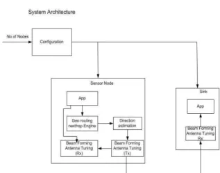
Fig. 5. Overall System architecture
The system architecture consists of a cofiguration block that creates a entire network having various sensor nodes and a sink node, which could be also called as a base station or the destination node to which the packets has to be diverted.
The sensor nodes will have the knowledge, as from which node the packet is received and to which node it has to be diverted. These all procedures will be carried over in the Geo routing next hop engine. This engine will calculate the nearest available node for the transimission of the packet and will be sent by using beamforming techique.
The sink node will be the destination part of the overall system, it just tunes to the desired location using the algorithm and receives the data packet Such implemetation is done by creating a Graphical User Interface (GUI) in MATLABR2010a. Such that as soon as the push button is pressed that corresponding function will be called and will be initiated. The GUI for the implementation is as shown in the fig. 6.
Fig. 6. Graphical User Interfacing block
Using GUI the MANET of 50 nodes is created in the area of 100*100 meters and the connection is established between the node say, for example, 18 to the base station 1which is highlighted. These are illustarted in the fig. 7 and fig. 8.
Fig. 7. Creating a Mobile Adhoc Network
Fig. 8. Establishing a connection between the nodes
IV.
SIMULATION RESULTS
In the simulation results, firstly we shall concentrate on the Constant Modulus Algorithm (CMA) output. CMA output is obtained as seen in the fig. 9. This shows that, after certain iterative steps the system converges to a constant value output which will be the exact location of the required node. And fig 10 explains the angle at which the packets are tranferred from one node to another. Say from node 18 to node 45 at an angle of -0.105322.Fig. 10. System log function
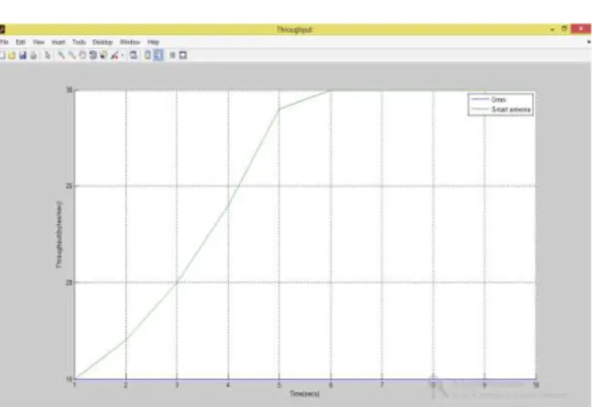
In this section we finalize by making comparisons between performance of omnidirectional antenna MANET and with that of SAS according to three performance metrics Bit Error Rate (BER) and Throughput.
Bit Error Rate: the number of bit errors divided by the total number of transferred bits during a studied time interval. BER is a unitless performance measure, often expressed as a percentage. The performance metric is shown in the fig. 11. Showing lower BER for SAS compared to omnidirectional antenna.
Throughput: The ratio of the total data reaches the receiver from the sender. The time it consume by the receiver to receive the last packet is called throughput. Throughput is illustrated in fig. 12. This has high significance of providing higher throughput to SAS MANET than Omnidirectional MANET.
Fig. 11. Bit Error Rate measurement
Fig. 12. Throughput measurement
V.
CONCLUSION
The performance metrics are plotted and the comparison between the MANET using SAS and the Omnidirectional antennas is obtained. Through simulation results we observed that using SAS provide better throughput as compared to omnidirectional antennas. And the Bit Error Rate is also less in SAS implementation than Omnidirectional antenna systems.
REFERENCES
[1] Constantine A. Balanis, Panayiotis I. Ioannides, ”Introduction to Smart Antennas”, Lecture #5, Copyright © 2007 by Morgan & Claypool.
[2] Mohammed A. Abdala and Areej K. Al-Zuhairy, “Integration of Smart Antenna System in Mobile Ad Hoc Networks”, International Journal of Machine Learning and Computing, Vol. 3, No. 4, August 2013.
[3] Azzedine Boukerche, “Algorithms and protocols for wireless and mobile ad hoc networks”, University of Ottawa, Canada, John Wiley & Sons, Inc., Hoboken, New Jersey,2009, p-p 129-164.
[4] Dr. Sunilkumar S. Manvi, Mahabaleshwar S.Kakkasageri, “Wireless and Mobile Networks Concepts and protocols”, Wiley India Pvt.Ltd, 2011, ch 8.
[5] Nwalozie G.C, Okorogu V.N, Umeh K.C, and Oraetue C.D, “Performance Analysis of Constant Modulus Algorithm (CMA) Blind Adaptive Algorithm for Smart Antennas in a W-CDMA Network”, International Journal of Engineering Science and Innovative Technology (IJESIT) Volume 1, Issue 2, November 2012.
and Performance Analysis Using Multimedia Traffic”, Journal of Basic and Applied Scientific Research, J. Basic. Appl. Sci. Res., 2(10)9925-9930, 2012 © 2012, TextRoad Publication.
[9] Sudip Misra l Isaac Woungang, Subhas Chandra Misra, “Guide to Wireless Ad Hoc Networks”,
http://www.springer.com/series/4198.
[10] Harkirat Singh and Suresh Singh, “ Smart-802.11b MAC protocol for use with Smart Antennas”, Department of Computer Science Portland State University.
[11] S. Bellofiore, J. Foutz, R. Govindarajula, I. Bahçeci, C. A. Balanis, A. S. Spanias, J. M. Capone, and T. M. Duman, “Smart antenna system analysis, integration and performance for mobile ad-hoc networks (MANETs),” IEEE Transactions on Antennas and Propagation, vol. 50, no. 5, May 2002.


