A Systematic Technique for Attenuation and
Dispersion Reduction in Fiber Optics
Communication using an Erbium Doped Fiber
Amplifier
Alexander .N Ndife
Member, IAENG,
Anthony .U Okolibe, Emmanuel .O Ifesinachi
Abstract —Optical fiber communication system limitations ranges from natural to artificial. In this work, the natural problems were understudied and enhancement solutions proffered using Erbium Doped Fiber Amplifier (EDFA). Experimental characterization was carried out over the period of 15months using MTN Fiber Optic backbone project as a test bed. The result obtained showed that amplification occurred in Erbium Doped Fiber Amplifier (EDFA) at 1550nm with almost zero attenuation and dispersion. With this technique it was observed that optic-electro and electro-optical conversion in normal amplification process which causes data losses was totally eliminated. The percentage of improvement in the research work compared with previous works was found to be 23%. The effectiveness of EDFA scheme deployed in reducing the attenuation and dispersion was shown in simulation result and Excel plots. A simulation validation showed an effective throughput response owing to zero dispersion and attenuation. From the data analysis result, it is feasible to address attenuation/dispersion issues in communication systems to a very minimal level with high electronic amplification.
Index Terms: attenuation, dispersion, Erbium Doped Fiber Amplifier (EDFA), fiber optics, wavelength.
Manuscript received June 29, 2015; revised July 23, 2015.
A. N. Ndife is with Anambra Broadcasting Service, Awka, Anambra State, Nigeria and also the Managing Director/CEO Ogugbalex Engineering Limited, N0.1 Marshal-Joe Road, Nsugbe, Nigeria. (Phone: +234(0)8037788356; e-mail: [email protected]).
A. U. Okolibe is with Computer Warehouse Limited, plot 13, block 54A Sir Foluso Giwa street lekki phase 1, Lagos, Nigeria (e-mail: [email protected]).
E. O. Ifesinachiis with the Electronic Development Institute, P.M.B 5099 Awka, Anambra State Nigeria (e-mail: [email protected]).
I INTRODUCTION
Optical fiber technology has advanced rapidly in recent years, today digital optical fiber systems are being installed in numerous telecommunications networks around the world. But its challenges have always being attenuation and dispersion which is regarded as natural problems. Improper design and operating capabilities which requires knowledge of the transmission characteristics of the optical sources, fiber, and interconnection devices such as connectors, couplers, and splices, could be viewed as artificial problems [1]. The transmission criteria that affect the choice of the fiber type used in a system are signal attenuation, information transmission capacity; which is the bandwidth, source coupling and interconnection efficiency [2]. However, as the data rates and fiber lengths increases, limitations due to dispersion and attenuation in the fiber became impossible to avoid. Dispersion was initially a problem when the first optical fibers, multimode step-index fiber, were introduced. Multimode graded-indexfiber improved the situation a bit, but it was single-mode fiber that eliminated severe multimode fiber related dispersion and left only chromatic dispersion and polarization mode dispersion to be dealt with by engineers [3]. In this work, an improved technique for reduction of limitations of signal loss as a result of attenuation and dispersion was dealt with deploying real-time approach.
temperature measurement range depend on the curvature radius of an optical fiber or waveguide and the kind of the optical waveguide on which the sensing process is implemented. The paper only considered a single source of problem of optic fiber without considering the fact that some losses are inevitable but this work provides a kind of compensator as well as a short cut out of the losses.
In [5] the researchers claimed that modal and chromatic material dispersion in a multimode optical fiber can be reduced by feeding the rays of the light beam into the end of the optical fiber, the angle of each ray relative to the axis of the fiber varied in accordance with the wavelength of the ray. Actually this can reduce these types of dispersion to an extent and worst leaving attenuation and other types of dispersion untouched. Therefore, improvement in this work could provide up to 1000 times gain stability and by this differ to a great extent from [6] which used gain-clamping method to deal with the EDFA stability. Here, EDFA stability was achieved by adding an extra light wave into the gain medium to share upper energy ions together with the signal lights. It proposed a gain-clamped C-band EDFA based on an off-line optical band-pass filter (OBPF) and obtained an optimized C-band EDFA which provides up to 20 times gain stability improvement for multi-wavelength fiber optical transport systems.
III RESEARCH METHODOLOGY
This research work is divided into three parts: the data collection part; data analysis part and validation part. Three different data rate configurations were setup while measuring the values for the outdoor distance of about 140km as shown in Table 1.EDFA was used as optical amplifier in the 1530nm to 1570nm regions of the spectrum. An external laser source of 980nm and 1480nm bands were used to pump light into the EDFA. Two base stations: transmitter and receiver located in Abakaliki and Enugu respectively were used, where the transmitter was configured to send data through the EDFA every 5seconds with retention period of 2minutes. The raw data collated was recorded in excel format and averaged in various cases of data rates as tabulated in table 3 for analysis. Simulation was later carried out to validate the result and
ascertain the effectiveness of EDFA used using MATLAB 2009b/Simulink.
IV RESEARCH DESIGN
This research was carried out using MTN fiber optic system (backbone) deployed along Enugu-Abakaliki expressway in eastern region of Nigeria within the period of 15months (January to April, 2013). Abakaliki served as the transmitting station while Enugu the receiver. This environment was characterized as semi-urban with a tropical savanna climate and its mean daily temperature is 26.7˚C (80.1˚F) [7]. It has high altitude and undulating terrain [8]. The test bed architecture was characterized into two parts: the transmission medium and the base stations. Optical fiber cable that covered the distance of 140km passing through bridges, hills, gully, streams etc was used as transmission medium. The base stations also have two components: the transmitter and receiver located at Abakaliki and Enugu respectively. The disphenser in the base station is where the EDFA were customized for measurements and its optimization.
V PROCEDURE FOR DATA COLLECTION The measurable quantities were the three (3) values for dispersion data rate with specified bandwidth and wavelength. As earlier mentioned, the base station EDFA was configured to send data across from the transmitter to receiver via an optical cable every 5 seconds and left for 2minutes in order to gather enough samples to be averaged. The data sent to the sink in the two occasions at different distances were recorded and saved after 2 minutes and above at data sample size of 20.
VI DATA ANALYSIS
Table 1: Data Rate Dispersion values Dispersion
with a Normalized DFB Laser Data Rates
Dispersion with a FP Laser Data Rates
Dispersion with a Narrow DFB Laser Data Rates 3.1GB/s 780Mb/s 3.11GB/s 1.55GB/s 270Mb/s 1.55GB/s 0.78GB/s 100Mb/s 0.78GB/s
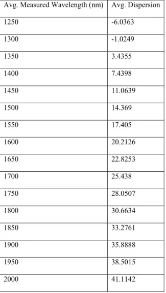
Table 2: Various Spectral Width (Dispersion) against wavelength in EDFA Avg. Measured Wavelength (nm) Avg. Dispersion
1250 -6.0363
1300 -1.0249
1350 3.4355
1400 7.4398
1450 11.0639
1500 14.369
1550 17.405
1600 20.2126
1650 22.8253
1700 25.438
1750 28.0507
1800 30.6634
1850 33.2761
1900 35.8888
1950 38.5015
2000 41.1142
In fig.1 shows that as the distance increases from 0 to 20km, the dispersion tends to increase with respect to the data rates. Fig.2 shows that dispersion penalty was gradual form 0 to about 110dB at 5km distance. Data rate of 780Mb/s at 5km recorded the highest attenuation while 270Mb/s at 50km
Table 3: three different data rates applied to EDFA at different wavelengths
Y1 Y2 Y3
0 0 0
45.8042 39.7560 33.7926
51.8247 45.7762 39.8118
55.3465 49.2980 43.3334
57.8453 51.7967 45.8321
59.7835 53.7349 47.7702
61.3671 55.3186 49.3538
62.7061 56.6575 50.6928
63.8659 57.8173 51.8526
64.8889 58.8404 52.8756
65.8041 59.7555 53.7908
66.6319 60.5834 54.6186
67.3877 61.3391 55.3744
68.0830 62.0344 56.0697
Fig 1 Dispersion penalty for the data link in EDFA operating at three data rates.
Fig 2 Dispersion penalty power output with three lower data rates in EDFA
Fig 3 Dispersion penalty of three narrow data rates in EDFA VII SIMULATION
In this work, simulation was realized using MATLAB 2009b/Simulink. The validation model of [9-11] with components: Bernoulli base station source Bbs, Gaussian
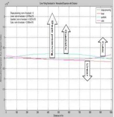
Minimum Shift Keying (GMSK) modulator, Attenuation/dispersion channel, Amplifier gain (EDFA) and Eye diagram was used. The Bernoulli generates the binary sequence which was modulated by GSMK as shown in fig.5. The choice of GSMK was owing to its merits: constant envelope, spectral efficiency, good BER performance and self-synchronizing capability. This modulated signal changed in this process of modulation in terms of shape, magnitude, phase etc. due to linear and nonlinear effects. EDFA amplifier decodes and bootstraps the signal into a sequence of digital data preparatory for decision making through eye diagram as shown in fig.4. Fig.5 is the simulation validation for EDFA, showing zero dispersion/attenuation responses with the use of gain amplifier. An effective throughput response due to zero attenuation and dispersion was shown in fig.6, while fig.7 depicts a curve fitting response for the attenuation/dispersion.
Fig 4: Validation Model for EDFA Optic Fiber Communication. Base
Station A Bernoulli
GMSK
Modulator Attenuation/ Dispersion
Amplifier
Fig 5 Simulation validation result showing zero attenuation/dispersion responses
Fig.6 An effective throughput response due to zero attenuation and dispersion
Fig.7 A curve fitting response for attenuation and dispersion
of cable routing (e.g. maintaining bend radius control) are the best ways to minimize signal impairments from excessive optical losses.
ACKNOWLEDGMENT
We thank in a special way the management of MTN Nigeria for the approval to use their facility for this research as a contribution to research development in Nigeria. Our profound gratitude also goes to Communication and Digital Signal Processing Research team of Electronic and Computer Engineering department, Nnamdi Azikiwe University, Awka for their unalloyed support. We are not forgetting our dear family members who stood by us in the course of this research.
REFERENCES
[1] Rader, N., “Fiber Optic Measurements”, Journal of Communications International, page 26 (1983).
[2] Miller, Stewart E., "Light-waves and Telecommunication", American Scientist, Sigma Xi, the Scientific Research Society, January–February 1984, Vol. 72, No. 1, pp. 66-71.
[3] Chromatic Dispersion Measurement of Multimode Graded-index and Single-mode Optical Fiber by phase-Shift Method TIA FOTP-168 (1992) [4] Fiber Optic Association Incorporation Newsletter, 2008.
[5] K. Valigura, M. Foltin, M. Blaho, “Transport System Realization in Simevents Tool”, 2007.
[6] Xhing-Hung Chang. Ami Amrullah “A Steady-Gain C-band EDFA for multi-wavelength Fiber Optical Transport Network” International journal of optoelectronic engineering, Vol.3 N0.1, 2003, pp 6-11.
[7] Official website of old Enugu state Nigeria, dated 21st june 2013 http://enugustate.gov.ng
[8] A geological field trip, June 2013.http://www.scharticles.com/geologic-field-trip.
[9] Rastislav Róka, Filip Čertík, “Modeling of Environmental Influences at the Signal Transmission in the Optical Transmission Medium”, International Journal of Communication Networks and Information Security (IJCNIS) Vol. 4, No. 3, December 2012.
[10] R. Róka, “Fixed Transmission Media. In: Technology and Engineering Applications of Simulink”, InTech, Rijeka (Croatia), pp.27, ISBN 978-953-51-0635-7.May 2012.
[11] F. Čertík, R. Róka, “Analysis of Modulation Techniques Utilized in the Optical Transmission Medium”, ELEKTRO – 9th International Conference, Žilina (Slovakia), 21. - 22. 5, ISBN 978-1-4673-1178-6, 2012.
Authors’ Profile
Ndife A.N is currently a postgraduate research student in Electronics and Computer Department of Nnamdi Azikiwe University, Awka, Nigeria. He also holds M.Eng. in Communications Engineering from the department. He is a member of IAENG (Reg. N0. 132482) and belongs to Society of Wireless Networks. E-mail: [email protected]. Phone: +234(0)8037788356.
Okolibe A.U is with Computer Warehouse Limited, Lagos, Nigeria. He is a postgraduate student in Electronics and Computer Engineering department of Nnamdi Azikiwe University, Awka, Nigeria. Email: [email protected].