UNIVERSIDADE DE ÉVORA
ESCOLA DE CIÊNCIAS E TECNOLOGIA
DEPARTAMENTO DE FÍSICA
Investigation, optimization and re- design of a
body car part, especially in terms of weight and
cost reduction, material substitution, structural
rigidity and fixation system.
Tiago Miguel Grilo Mayer de Oliveira
Orientação: Prof. Eng. José Eugénio Garção
Diplom. Eng. Hilmar Schulze
Mestrado em Engenharia Mecatónica
Dissertação
i
ii
Universidade de Évora
Mestrado em Engenharia Mecatrónica
MSc Dissertation
Investigation, optimization and re- design of a body car part,
especially in terms of weight and cost reduction, material
substitution, structural rigidity and fixation system.
Author:
Tiago Miguel Grilo Mayer de Oliveira
Coordinator Universidade de Évora:
Prof. Eng. José Eugénio Garção
Co-Coordinator Volkswagen AG:
iii
Inspiration
“My interest is in the future because I am going to spend the rest of my life there.”
Charles Kettering
“First say to yourself what you would be, and then do what you have to do.”
Epictetus
“Wherever you go, go with all your heart.”
Confucius
“Opportunity is missed by most people because it is dressed in overalls and looks like work.”
Thomas Edison
“A person, who never made a mistake, never tried anything new.”
Albert Einstein
“Be the change you want to see in the world”
v
The research reported in this thesis is supported by Universidade de Évora, Portugal.
The research reported in this thesis is part of the product improvement process of Volkswagen Entwicklung Aufbau.
Veröffentlichungen über den Inhalt der Arbeit sind nur mit schriftlicher Genehmigung der Volkswagen AG zugelassen. Die Ergebnisse, Meinungen und Schlüsse dieser Dissertation sind nicht notwendigerweise die der Volkswagen AG
Publications about the content of this work require the written consent of Volkswagen AG.
vi
Universidade de Évora advisor:
Prof. Eugénio Garção
Volkswagen AG Co-advisor:
vii
Abstract
Reducing vehicle mass in order to improve fuel efficiency is one of the biggest challenges of actually automotive society. This objective could be achieved using lighter materials or less pollutant engines, nevertheless these technologies are currently expensive and engineers must develop high efficient safety vehicles that could be economically competitive in their class. The immediate objective of this research is to analyze a body car part in order to improve its weight characteristics without compromising the main function of the component as well as the final price per unit. Different alternatives were taken into study, selecting the lightweight design as the best practice to implement in this case, reducing substantially the weight of the part, keeping strength resistance and lowest price as possible.
viii
Investigação, Otimização e Redesenho de uma Peça Automóvel,
especialmente em termos de redução de massa e custos,
substituição de material, rigidez estrutural e sistema de fixação.
Resumo
Reduzir a massa total de um veículo de modo a melhorar a sua eficiência energética é um dos maiores desafios dos grandes construtores automóveis. Este objetivo pode ser atingido através da utilização de materiais mais leves ou motores menos poluentes, contudo estas tecnologias ainda são demasiado dispendiosas, sendo que os engenheiros responsáveis pelo desenvolvimento de um novo modelo, devem fazê-lo tendo como sempre premissa um veículo extremamente eficaz em termos de segurança, sendo economicamente competitivo na sua classe. Este estudo tendo como objetivo analisar um componente utilizado na construção da carroçaria de um veículo atualmente no mercado, de modo a otimizar a sua massa, não comprometendo a sua função principal assim como o preço final por peça. Diversas alternativas foram tidas em conta, tendo sido optado como caso mais favorável a otimização de design, reduzindo substancialmente a massa do componente, mantendo a sua resistência e o mínimo investimento possível.
ix
Acknowledgements
I would like to thank my company supervisor, Dipl. Eng. Hilmar Schulze, for the great opportunity of being project integrated in the biggest European car manufacturing Group, Volkswagen AG, in order to proceed with this project. I would like also to thank to my University de Évora supervisor, Prof. Eugénio Garção, for all the support and good practices from Portugal during the most critical stages of this study.
Special thanks to all my family and closest friends, for all the strength and courage given during the last months.
xi
Table of Contents
Inspiration ... iii Abstract ... vii Resumo ... viii Acknowledgements ... ix Table of Contents ... xiList of Figures ... xiii
List of Tables ... xx
Nomenclature ... xxi
1 ... 23
Introduction ... 23
1.1 - Project Environment ... 23
1.2 - The Volkswagen Group ... 24
1.3 - Product Improvement Process ... 26
1.3.1 – Strategy and premises ... 26
1.4 - Safety in Automobile Vehicles ... 31
2 ... 32 The Project ... 32 2.1 - Introduction... 32 2.2 - Premises ... 36 2.3 - Benchmark ... 37 2.4 - Constraints ... 44 2.4.1– Design Constraints ... 44 2.4.2– Body Constraints ... 47 2.4.3- Trim Constraining ... 50
xii
3 ... 54
Characteristics of the part in actual production ... 54
3.1 - Introduction... 54
3.2 - Material Properties ... 55
3.3 - Metal Parts Cold Forming Stamping Process ... 57
3.4 - Welding Connections in the Current Part ... 87
3.5 - Welding Connection From Actual Part to Body Structure ... 90
4 ... 105
Current Part Modeling and Testing ... 105
4.1 - Introduction... 105
4.2 - The ECE R14 ... 105
4.3 - Virtual Major Deformations ... 110
4.4 - Deformations Confirmation After a Physical Crash-Test ... 134
5 ... 138
Part Improvement ... 138
5.1 - Introduction... 138
5.2 - Improvements Possibilities ... 138
5.3 - Geometry Improvement ... 141
5.4 - Considering Different Materials and Thicknesses ... 155
5.5 - Simulations ... 158
5.6 - Comparison of the Various Designs ... 165
5.7 - Project Feasibility ... 168
5.7.1.– Selected Designs Associated manufacturing costs ... 168
5.7.2.– Cost Analysis ... 170
6 ... 172
Conclusions and Recommendations ... 172
6.1 - Conclusions ... 172
6.2 - Recommendations ... 173
xiii
List of Figures
Figure 1: Flowchart from a product improvement process. (Volkswagen product improvement process
flowchart) ... 28
Figure 2: Three-point seat belt system. (Delphi, Inc.) ... 31
Figure 3: 2010 Volkswagen Sharan dimensions. (Volkswagen AG) ... 33
Figure 4: Seat belt guide rail. ... 35
Figure 5: 2010 Volkswagen Sharan Body structure upper view and rail guide representation. (Volkswagen AG) ... 35
Figure 6: 2010 Volkswagen Sharan Body interior roof view and rail guide representation. (Volkswagen AG) .. 36
Figure 7: Volkswagen Touran second seats row middle seat belt first point fixation. ... 38
Figure 8: Ford Galaxy second seats row middle seat belt first point fixation. ... 39
Figure 9: Second seats row from an Audi Q7. (Audi AG) ... 40
Figure 10: Second row middle seat’s seat belt fixation concept from Ford Grand C-Max... 41
Figure 11: Second row middle seat’s seat belt fixation concept from Mazda 5. ... 42
Figure 12: Second row middle seat’s seat belt fixation concept from Opel Meriva. ... 43
Figure 13: Second row middle seat’s seat belt fixation concept from Nissan Qashqai. ... 44
Figure 14: 2010 Volkswagen Sharan interior seats perspective with particular attention to the second seat row middle seat belt. (Volkswagen AG) ... 45
xiv
Figure 15: 2010 Volkswagen Sharan interior seats perspective, with special detail to the “bubble” where is
located the seat belt retractor. (Volkswagen AG) ... 46
Figure 16: 2010 Volkswagen Body Structure. (Volkswagen AG) ... 47
Figure 17: Connection between rail guide and rear cross member. ... 48
Figure 18: Connection between rail guide and C-pillar. ... 48
Figure 19: Volkswagen Sharan virtual representation from Body structure with Trim parts involved in constraints. ... 50
Figure 20: Virtual representation from C-Pillar with Trim parts involved in constraints. ... 51
Figure 21: Virtual representation from rear cross member with Trim parts involved in constraints. ... 51
Figure 22: Rail Guide with seat belt assembled. ... 53
Figure 23: Development cycle of a stamped part tool in 1985. ... 57
Figure 24: Nowadays development cycle of a stamped part tool. ... 58
Figure 25: Schematic of a stamping press and diferent dies / operation used to have a formed part. (Simtech, 2009) ... 60
Figure 26: Schematic of a stamping tool. (Simtech, 2009) ... 60
Figure 27: Schemtaic of a single operation and behaviour of the formed part. (Simtech, 2009) ... 61
Figure 28: Dieface geometry of a specific station. (Simtech, 2009) ... 62
Figure 29: Simple cutting patters normally used in prduction. (Simtech, 2009) ... 62
Figure 30: Stamping station. (Simtech, 2009) ... 63
Figure 31: Coining station. (Simtech, 2009) ... 63
Figure 32: Trimming station. (Simtech, 2009) ... 64
Figure 33: Punching and flanging station. (Simtech, 2009) ... 64
Figure 34: Basic geometry featurs identified in a dieface design. (Simtech, 2009) ... 65
Figure 35: Flat blank geometry for actual part’s stamping process with 1mm thickness. ... 66
xv
Figure 37: First stamping stage: Main volume and geometry. (Volkswagen Stamping Simulation
Department) ... 67
Figure 38: Gravity Fall phase of a stamping operation. (Simtech, 2009) ... 67
Figure 39: Holding phase of a stamping operation. (Simtech, 2009) ... 68
Figure 40: Forming phase of a stamping operation. (Simtech, 2009) ... 68
Figure 41: Fisrt part or Volume creation during a Forming phase. (Simtech, 2009) ... 69
Figure 42: Second part or Geometry cretion during a Forming phae. (Simtech, 2009) ... 69
Figure 43: Operation 3 from the stamping process, where holes are opened and 5 trim flanges cut. (Volkswagen Stamping Simulation Department) ... 70
Figure 44: Part geometry on operation 3 with detailed holes to be implemented. (Volkswagen Stamping Simulation Department) ... 70
Figure 45: Perforating operation. (Dayton Progress Corporating, 2003) ... 71
Figure 46: Zoom view from detail C on Figure 44. ... 72
Figure 47: Lancing operation. (Dayton Progress Corporating, 2003) ... 73
Figure 48: Detailed view from seat belt guide fixation. ... 73
Figure 49: Shear angles configurations. (Dayton Progress Corporating, 2003) ... 74
Figure 50: Springback phenomenon after extraction from the tool. (Simtech, 2009) ... 75
Figure 51: Piloting operation. (Dayton Progress Corporating, 2003) ... 75
Figure 52: Location the part material in the stamping tool using Piloting. (Dayton Progress Corporating, 2003) ... 76
Figure 53: Feed release during a Piloting operation. (Dayton Progress Corporating, 2003) ... 76
Figure 54: Stripper contact during Piloting operation. (Dayton Progress Corporating, 2003) ... 77
Figure 55: Feeding operation. (Dayton Progress Corporating, 2003) ... 78
Figure 56: Open tool for a new cycle. (Dayton Progress Corporating, 2003) ... 78
Figure 57: Operation 4. Final trim flanges are cut. (Volkswagen Stamping Simulation Department) ... 79
xvi
Figure 59: Inverse simulation representation. (Simtech, 2009) ... 80
Figure 60: Inverse method simplication. (Simtech, 2009) ... 81
Figure 61: Simplified inverse method error. (Simtech, 2009) ... 82
Figure 62: Part thickness deviations in %. (Volkswagen Stamping simulation department) ... 82
Figure 63: More critical areas regarding crack possibility in actual rail guide during stamping process. (Volkswagen Stamping Simulation Department) ... 84
Figure 64: Risk of crack in Detail 1 area. (Volkswagen Stamping Simulation Department)... 85
Figure 65: Risk of crack in Detail 2 area. (Volkswagen Stamping Simulation Department)... 86
Figure 66: Risk of crack in Detail 3 area. (Volkswagen Stamping Simulation Department)... 86
Figure 67: Rail guide including speed nut and stud representation. (Volkswagen AG) ... 87
Figure 68: The principle of projection welding. (Ruukki, 2009) ... 88
Figure 69: The making of a projection, punch and die. . (Ruukki, 2009) ... 89
Figure 70: 2010 Volkswagen Sharan Body structure. (Volkswagen AG) ... 91
Figure 71: Support function from the Rail Guide to the open roof frame, including the D-ring seat belt fixation point. ... 91
Figure 72: Rail Guide in the Body structure. ... 92
Figure 73: Connection between Rail Guide and C-pillar upper reinforcement with 6 weld spots. The components have 1mm and 1.2mm thickness respectively. ... 92
Figure 74: Connection between Rail Guide and rear roof cross member with 11 weld spots. The components have 1mm and 0.9mm thickness respectively. ... 93
Figure 75: Ordinary spot / projection welding machine. (Ruukki, 2009) ... 94
Figure 76: Different kinds of transformer solutions used in resistance welding. (Ruukki, 2009)... 95
Figure 77: The principle of spot welding. (Ruukki, 2009) ... 96
Figure 78: Spot weld. (VW 01105-1) ... 96
Figure 79: Spot weld section. (VW 01105-1) ... 97
xvii
Figure 81: Peel-test. (Ruukki, 2009) ... 101
Figure 82: Shear test. (VW 01105-1) ... 102
Figure 83: Cross tension. (VW 01105-1) ... 103
Figure 84: Peel tension. (VW 01105-1) ... 104
Figure 85: Sketch of the load application on the seat belt according to ECE R14. ... 106
Figure 86: Lap block from an ECE R14 test. (ECE R14) ... 107
Figure 87: Shoulder body block from an ECE R14 test. (ECE R14) ... 108
Figure 88: Volkswagen Sharan ECE R14 test for the second row seats. (Volkswagen Simulation Department) ... 109
Figure 89: Volkswagen Sharan ECE R14 test for the second row seats. (Volkswagen Simulation Department) ... 110
Figure 90: Complete Vehicle frontal impact simulation. (Volkswagen Simulation Department) ... 111
Figure 91: Reduced model, contemplating only the guide rail and the other parts where it is connected. ... 112
Figure 92: ANSA® starting menu. ... 113
Figure 93: Material definition in ANSA®. ... 114
Figure 94: Different element types possible to choose inside ANSA® software. (BETA CAE Systems S.A.) ... 115
Figure 95: Example of shell element definition in ANSA®. ... 116
Figure 96: Mesh model modeled using ANSA® application. ... 118
Figure 97: Detailed representation from the mesh in D-ring fixation point. ... 119
Figure 98: Detailed representation from critical area 2 on Figure 96. ... 120
Figure 99: Boundary conditions definition. ... 122
Figure 100: Nodal constraint spot weld option. (S.M. Molenaar, 2009) ... 123
Figure 101: Spot weld location and connected nodes. (S.M. Molenaar, 2009) ... 124
Figure 102: Spot weld model. (S.M. Molenaar, 2009) ... 125
xviii
Figure 104: load components applied to rail guide ... 126
Figure 105: Loads representation on Figure 85 point 3. ... 127
Figure 106: Loads representation on Figure 85 point 2. ... 127
Figure 107: Loads applied to the guide rail. ... 128
Figure 108: PAM-CRASH® explicit dynamic simulation input. ... 130
Figure 109: Representation of a Frontal impact simulation and consequent deformations to guide rail. (Volkswagen Simulation Department) ... 130
Figure 110: D-ring fixation point and consequent deformation during a frontal impact. (Volkswagen Simulation Department) ... 131
Figure 111: Retractor fixation point and consequent deformation during a frontal impact. (Volkswagen Simulation Department) ... 132
Figure 112: Possible cracked area on C-pillar after a front impact Finite Elements simulation. (Volkswagen Simulation Department) ... 132
Figure 113: Equilibrium path or Plot with representation of the response (load-displacement) diagram that characterizes the load application on the D-ring fixing point. (Volkswagen Simulation Department) .... 133
Figure 114: Euro NCAP frontal impact test overview. (Euro NCAP website) ... 135
Figure 115: 2010 Volkswagen Sharan during a front impact test. (Volkswagen Body Engineering) ... 136
Figure 116: a) Guide rail before performing a frontal impact test; b) Guide rail after performing a frontal impact test. (Volkswagen Simulation Department) ... 137
Figure 117: Main contact point between rail guide and other components. (Volkswagen Body Engineering) .. 140
Figure 118: CAD representation from improvement possibility Version A. ... 143
Figure 119: CAD representation from improvement possibility Version A. ... 144
Figure 120: Comparison between actual part (red) and Version A improvement (blue). ... 145
Figure 121: Comparison between actual (red) and improved part (blue), on rear cross member area... 146
Figure 122: Comparison between actual (red) and improved part (blue), on C-pillar area. ... 147
Figure 123: Comparison between actual (red) and improved part (blue), on contacting flanges middle area between Rail Guide and Roof... 148
xix
Figure 124: Reposition of a spot weld regarding flange dimension improvement. (Volkswagen Body
Engineering) ... 149
Figure 125: Detailed view from the new holes implemented. ... 150
Figure 126: Version A middle channel width improvement. ... 151
Figure 127: Comparison between actual (red) and improved part (blue), on middle section reinforcement channels. ... 152
Figure 128: Actual reinforcement channel with fixation points from seat belt guides. ... 152
Figure 129: New geometry from the reinforcement channels including guides fixation points. ... 153
Figure 130: New configuration from the reinforcement channels. ... 153
Figure 131: 3D design from the reinforcement channels. ... 154
Figure 132: New holes introduction on both reinforcement channels. ... 155
Figure 133: Reduced model, contemplating only the improved guide rail and the other parts where it is connected. ... 159
Figure 134: Mesh model modeled using Visual-Mesh application. (Volkswagen Simulation Department) ... 160
Figure 135: Plot with part displacement during load application. (Volkswagen Simulation Department) ... 161
Figure 136: Graphic representation from Detail A on Figure 135, regarding displacement [mm]. (Volkswagen Simulation Department) ... 162
Figure 137: Graphic representation from Detail B on Figure 135, regarding displacement [mm]. (Volkswagen Simulation Department) ... 162
Figure 138: Graphic representation from Detail C on Figure 135, regarding displacement [mm]. (Volkswagen Simulation Department) ... 163
Figure 139: Graphic representation from Detail D on Figure 135, regarding displacement [mm]. (Volkswagen Simulation Department) ... 164
Figure 140: Rupture point on C-pillar. (Volkswagen Simulation Department) ... 164
Figure 141: “Snap-back” points during simulation from the component in study with Version A, HC450XD material and 0.85mm thickness. (Volkswagen Simulation Department) ... 165
xx
List of Tables
Table 1: Chemical composition in % of grade from the low alloy steel HC340LA. ... 55
Table 2: International equivalent grades from the low alloy steel HC340LA. ... 55
Table 3: Components of a stamping design ... 59
Table 4: Dimensions used in the making of an embossed projection (Ruukki, 2009) ... 89
Table 5: Welding parameters for cold rolled and coated sheets. (Ruukki, 2009) ... 99
Table 6: Flange geometry and spot weld application regarding part thickness. (VW 01105-1) ... 101
Table 7: ECE R14 test loads according to vehicle’s mass in tons. (ECE R14) ... 107
Table 8: Detailed model components characteristics regarding material and thickness. ... 117
Table 9: Different materials and thicknesses considered to improve the Version A and Version B. ... 156
Table 10: Influences from thickness to areas, volumes and masses considering Version A and Version B of the rail guide. ... 157
Table 11: Improvement variants analyze regarding different materials and thicknesses. ... 166
Table 12: Official quotation from Gestamp Portugal ... 169
Table 13: Official project feasibility according to quotation from Gestamp Portugal and necessary lead time to its profitability ... 171
xxi
Nomenclature
Roman lowercase
symbol description unit
n Strain hardening coefficient -
e Elongation mm
p Surface pressure Pa
Roman uppercase
symbol description unit
P Performing force N
T Thickness of part material mm
S Shear strength
E Young modulus -
Greek
symbol description unit
Friction force N
ε Membrane strain mm
Mathematical notation
symbol description unit
Tensile strength MPa
0.2% proof strength MPa
Yield stress MPa
Elongation to failure %
xxii
Acronyms
VW Volkswagen
UE Universidade de Évora
EK Entwicklung Aufbau
ECE Economic Commission for Europe TSI Twincharged Stratified Injection TDI Turbocharged Diesel Injection
hp Horsepower
DIN Deutsches Institut für Normung HSLA High-strength low-alloy steel JIS Japanese Industrial Standards
AFNOR Association Française de Normalisation
23
1
Introduction
Abstract: In this chapter, an introduction of Volkswagen Group is given, accompanied by
an overview of the current improvement process used by Volkswagen in order to reduce mass and cost for vehicles already in production, which was used as aim for this research.
1.1 - Project Environment
One of biggest concerns in the actually society is the increasing of Global Pollution and all the problem advent from this factor. Automotive industry is one of the biggest contributors for this problem and despite the auto manufacture itself; automobile exhausts emit several components that have adverse health impact among the exposed population.
Rapid increase in the number of vehicles is another reason for increasing automobile pollution and in order to counter this tendency, automotive manufacturers and their suppliers must innovate in all areas of vehicle design in order to maximize fuel efficiency and reduce emissions.
In order to achieve this goal, automotive manufactures can adopt several strategies, starting on more efficient engines, redesigned better aerodynamic autos,
eco-This chapter is largely based on internal Volkswagen AG information, including Volkswagen Official Website and product improvement process.
24
friendly tires or the latest tendency, new lightweight materials and their integration into vehicle designs.
Reducing vehicle mass by using lighter materials is one of the means to improve fuel efficiency, a feature society as a whole is pushing aggressively toward. In order to address the potential safety concerns associated with lightweight materials, new technologies and tools are being innovated, and can be used in the design of vehicles to achieve both the energy and safety goals. Advanced modeling and simulation using high performance computers will be necessary to quickly develop entirely new materials, while ensuring vehicle performance, safety, and efficiency. The lightweight, energy-efficient vehicles of the future will be manufactured out of materials that do not even exist today: materials that will be lighter, stronger, safer, and more environmentally friendly than current materials. The application of new lightweight materials goes well beyond ground vehicles, as well. Aviation, commercial transport, shipping, and many other sectors can benefit from lightweight materials.
Although lightweight materials are more expensive than the current steal used in automobile manufacture and this is the real challenge that engineers have to overtake in order to develop high efficient safety vehicles that could be economically competitive in its class.
1.2 - The Volkswagen Group
The Volkswagen Group has its headquarters in Wolfsburg and it is actually one of the world’s leading automobile manufacturers and the largest vehicle maker in Europe.
In 2012, the Group increased the number of sold vehicles from 8.265 million in 2011 to 9.3 million.
25
In Western Europe, Volkswagen Group represents 23% of new vehicles market, which revenue in 2011 totaled 192.7 billion euros regarding sales. Profit after tax in the 2012 financial year amounted to €21.9 billion, €6.1 billion more as in 2011.
Currently the Volkswagen Group is composed by 12 brands from seven different European countries: Volkswagen Passenger Cars, Audi, Porsche, Volkswagen Commercial Vehicles and MAN from Germany, SEAT from Spain, Bentley from United Kingdom, Bugatti from France, SKODA from Czech Republic, Lamborghini and Ducati from Italy and Scania from Sweden.
Each brand has its own character and operates as an independent entity on the market. The product spectrum extends from low-consumption small vehicles (Volkswagen up!, SEAT Mii or SKODA Citigo) to luxury class (Audi A8) or super sport automobiles (Bugatti Veyron or Lamborghini Aventador) and more recently to motorbikes with Ducati. In the commercial vehicle sector, the product offering ranges from pick-ups (Volkswagen Amarok) to buses and heavy trucks with MAN, Scania or especially in South American market with Volkswagen Trucks.
The Volkswagen Group is also active in other fields of business, manufacturing large-bore diesel engines for marine and stationary applications (turnkey power plants), turbochargers, turbomachinery (steam and gas turbines), compressors and chemical reactors, and also producing vehicle transmissions, special gear units for wind turbines, slide bearings and couplings as well as testing systems for the mobility sector.
As curiosity, Volkswagen Group is also active in food service industry with Volkswagen ServiceFactory, not only to serve meals to its employees in each plant but also the sell to general public. Taking an example “Volkswagen Currywurst” or “Volkswagen Ketchup” are already cult item in some cities around Germany.
According to 2012 data, Group had 100 production plants in 18 European countries and a further nine countries in the Americas, Asia and Africa, employing
26
550.000 workers worldwide, producing 34,500 vehicles or involved in vehicle-related services in 153 different countries.
As Volkswagen Group’s goal to offer attractive, safe and environmentally friendly vehicles which are competitive on nowadays market and which set world standards in their respective classes.
This development has made Volkswagen AG not only one of the world’s largest company within the automobiles production sector with 9.3 Million vehicles sold in 2012, but also a true global player.
1.3 - Product Improvement Process
This project started integrated in the Volkswagen’s product improvement process for series vehicles. This program has as main goal the reducing the mass and/or costs regarding product in a current series production vehicle, each means search for some new strategies, new ideas or new standards in order to reduce the total mass and/or costs of a singular part and consequently improve the vehicle.
1.3.1 – Strategy and premises
A product improvement process is started based on an improvement idea to a specific vehicle or platform, each means that, this kind of program could be used not only in a specific part for a specific model vehicle, but also integrated in a whole class or segment involving several different models in different plants around the world – platform components.
At a first analyze it is easier to implement an improvement in one part for one single vehicle, where is necessary to involve one supplier, a single plant that produces
27
the vehicle and also in case of special parts that request crash-test or other special tests, it would be simpler and faster to proceed.
However, in several cases in order to improve significantly one part it is requested a higher investment, which could not be feasible considering the production volume of one single model. Regarding this issue and also taking in mind all the bureaucratic process behind, often it is better to improve a part that is common to several models, where the considered the total volume is higher and easier to amortize the investment.
Independently on how complex is a specific product improvement process, there is always a multidisciplinary team behind each project. This means that each idea have a team constituted by people from different departments in order to analyze the consequences of each change. Taking an example, in order to improve the geometry of a single metal part, it is necessary at first time the responsible engineer, who makes the improved design, after the buyer/ purchasing department contacts the supplier in order to see each are the impacts of this ne geometry to his current production process (new tools, new process flow, new logistic processes) and also all the requested investment in order to have the new part. At the same time the affected plants are also contacted in order to check if the new part will need new assembly and logistic processes with the necessary investment associated. Finishing the consulting step, the product improvement process coordinator for each area together with financial department will check the feasibility of the project. In this case for all the product improvement processes, they should be profitable after maximum of 12 months, i.e. all the investment must be paid after 1 year of introduction, including already the mass or cost improvement.
When a project is feasible would be presented to the Volkswagen board and implemented in the vehicles.
28
Starting to do a deeply analyze of the product improvement process, in is important to understand step by step what is really done. The program is divided in 6 main stages, as presented on Figure 1.
Figure 1: Flowchart from a product improvement process. (Volkswagen product improvement process flowchart)
Each step is based in different premises and also, as referred before, made by different departments.
Starting with stage 1 “Idea generation”, different ideas could come from different ways. A single worker could raise it or most commonly, Volkswagen has its own ways in order to find improvements possibilities.
First method is based on meetings, where are discussed specific parts that were already identified as items with improvement potential. In these meetings, those parts are compared to similar parts or concepts, not only inside the Volkswagen Group but also to concurrent vehicles. In the second case, Volkswagen’s part are analyzed against to other brands, knowing the price from a concurrent part, it is proposed to do the necessary actions in order to develop a better and cheaper one.
Another very effective method consists in several meetings including different departments, where vehicles from other automobile groups are analyzed in order to find good practices already implemented and better concepts with more improvement capacity that could be used by Volkwagen’s vehicles.
Third Method is the electronic analyze, where suppliers from electronic components, those usually are common not only between brands inside the same automobile group but also between different group, as example Bosch, which supplies
Idea generation Idea’s Potential Necessary actions Actions Decision Action implementation Financial confirmation
29
not only all brands in Volkswagen Group but also BMW Group and Mercedes, analyze the parts that they supply, which could be Hardware or Software, comparing and trying to improve them.
At the same time is also possible to have the same process with another type of suppliers. In this case the collaborators from Volkswagen together with the supplier try to improve some parts or processes inside the supplier plants.
Continuing with the same philosophy, there is another used concept; where different suppliers are nominated and together with Volkswagen departments try to find improvements in their supplied components or processes. This kind of method is more used when the same part is delivered from 2 or more different suppliers and it is necessary a mutual agreement between all companies.
Similar to the previous methods, there is another concept where the plant that uses a specific part is nominated in order to participate and help in the improving process. In this case not only the part is analyzed but also all the assembly process, in order to be improved, reducing the total costs of the vehicle.
The last existent used method consists in the nomination of a multidisciplinary team in order to make a Benchmark not only between brands and concepts but also between regions.
Different regions have different specifications and could occur that a specific improvement in Europe can have negative impacts on plants or sales in other continents. This type of Benchmark is more often used in costumer relevant changes, where specific markets are analyzed in a costumer point of view.
The second step from a product improvement process is called Idea’s potential. Where engineers and buyers must analyze if the improvement ideas are technical feasible and are according to safety regulations. Regarding buyers, it is also required to
30
have all the costs from the supplier, especially when are materials or processes modifications.
After analyze, the results are shown in multifunctional team meetings to be discussed. At this stage all the documentation regarding idea sheet, costs sheet and basic presentations are starting to be prepared.
The third stage is where necessary actions are discussed. In this step all the improvements have already associated costs and technical feasibility and they are presented to the responsible from all markets and/or plants where it is planned to introduce the component, in order to have a direct approval. In case of design or costumer relevant parts, the proposals must be sent to the marketing and design departments in order to be accepted.
After the presentation of each improvement in a product improvement process pre-meeting the official alteration sheet is started and the product team from the affected model is informed in order to decide on each model’s update could be implemented the changed part.
Continuing with the regular process, all the improvements are presented to Volkswagen board. This process is the fourth stage from a product improvement process program which is called Actions Decision.
At this stage improvements can be presented in 2 different ways: costumer or design relevant are presented as a prototype part already assembled in the vehicle, in order to have a better overview of what consist exactly the alteration; or in the improvement sheet when the part is not costumer or design relevant.
After an official approval by the board, the improvement is confirmed in Volkswagen’s systems and, as referred before, product team must define on each model’s upgrade will be implemented, which could occur twice per civil year.
31
The last 2 steps are Actions Implementations and Financial Confirmation, where improved parts are implemented in production as well as all the financial improvement as cost or mass reduction per part is confirmed.
1.4 - Safety in Automobile Vehicles
Taking a brief analyze from automobile safety, Volvo was the first vehicle manufacturer to offer a nowadays known front-seat three-point seat belt as standard equipment in Volvo Amazon in 1959. This kind of technology has as main function a better restrain of the occupant during an impact to prevent his ejection, comparing to a two-point seat belt equipment.
This system is shown on Figure 2 and proved to be a great improvement in automobile security and nowadays it is requested by law for whole vehicle’s seats.
32
2
The Project
Abstract: In this chapter, an introduction from the project is given, taking special attention
on the basic premises necessary to its development. Other aspects as constraining for an improved design and benchmark through different concurrent vehicles with similar concepts will be also approached.
2.1 - Introduction
In this Project it is proposed to investigate one body vehicle part in order to improve it reducing substantially its mass not compromising its basic functions. This body vehicle component is a seat belt guide rail from the second seat’s row middle seat present in 2010 Volkswagen Sharan. It is proposed to investigate new technologies, new materials and also new geometries to achieve the maxim improvement in terms of mass taking always into account the final price and the necessary investment of the part in order to use it in current production.
As referred before, the vehicle in study is the second-generation from Volkswagen B-class MPV, which was launched at the 2010 Geneva Motor Show and a month later the second-generation of its sibling model, the SEAT Alhambra, was officially announced.
This chapter is largely based on internal Volkswagen AG information, including Volkswagen Forschung und Entwinklung and Volkswagen Wettberwerbanalyse.
33
Although still built at the Volkswagen Autoeuropa plant in Portugal, the new model inherits only its name from the previous Sharan, compared to which it is 220 mm longer, 92 mm wider and 12 mm lower, with the wheelbase lengthened by 75 mm.
Figure 3: 2010 Volkswagen Sharan dimensions. (Volkswagen AG)
Mass has been reduced by 30 kg, having now 1723kg (considering the engine 1.4TSI, 148 hp). The initial engine range comprises 1.4-litre TSI (148 hp) and 2.0-litre (197 hp) petrol options, plus two 2.0-litre TDI diesel engines, rated at 138 and 168 hp. The rear doors now slide open rather than being hinged.
This vehicle is 7 seats MPV placed in the B-Segment analog to Ford Galaxy, Mazda 5, Renault Espace and Citröen C8. According to the latest market studies, this vehicle segment is one of the first options to big families with 2 / 3 children or to mid / big size companies not only to use in day by day but especially for big travels, mainly due to the characteristics of this type of vehicles: very comfortable and with the same technological solutions as a normal / premium midsize vehicle with more free interior
34
space, better design as minivan and functional not only to transport passengers but also carry goods.
In this segment, the compromise between interior passenger’s safety, free space and comfort and also fuel economy is very important to the final costumer. Taking this aspect as main premise, manufactures work hard in order to offer the most safer vehicle with the biggest interior free space and comfort that can run the more kilometers with less petrol as possible. This is actually the biggest challenge to automotive engineers: relation comfort / fuel economy.
The relation comfort vs. economy takes even a more important step when the final price is the most important factor for approximately 90% of the costumers. It is possible to develop a super lightweight vehicles using materials specially made for motorsport or aeronautic proposals, including all the top technology and maximal fuel economy, however its final price would be something not achievable to an ordinary costumer that search for this type of vehicles. Due to this fact, nowadays the strategy is offer to public a vehicle with high technology equipment in terms of comfort and safety, more advanced fuel economy engines and with an improved lightweight design using not only lightweight material but mostly using most advanced engineering design parts. With this last aspect it is possible to produce and sell a lightweight vehicle with a reasonable price that costumers can afford.
Following this philosophy and taking part on the Volkswagen Group’s product improvement process program (described on 1.3 Product Improvement Process), this project will have its focus on one particular Body part in order to improve it and having always in minded the cheapest price and the lowest investment as possible.
The part itself, as already referred, is a seat belt guide rail used as the second row middle seat belt fixing point from the restraint system. This component is made by HC340LA High- strength low-alloy steel with 1917g total mass including all subcomponents, with approximately 1475mm length and 200mm width.
35
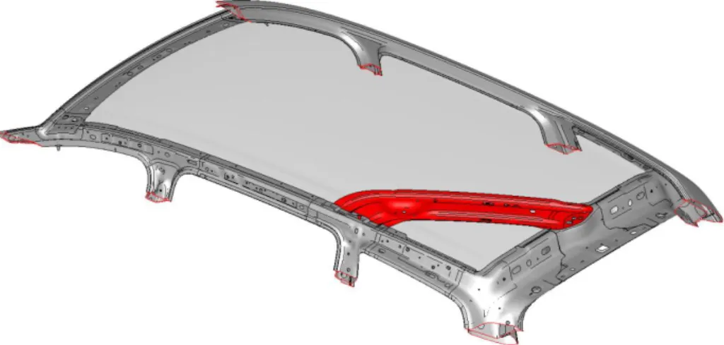
Figure 4: Seat belt guide rail.
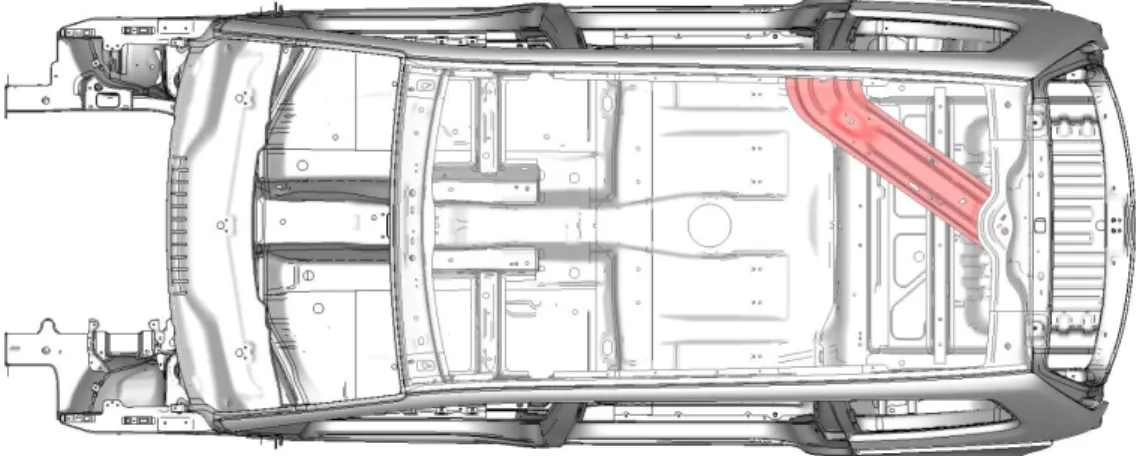
This part is located in the upper area from the body structure, connecting the rear cross member and the C-pillar upper reinforcement, in order to guide the seat belt to the second row middle seat. It has also the important function retractor fixation point on the rear area (detail 2 Figure 4) and the D-ring (detail 1 Figure 4) near the C-pillar in order to provide the best security and comfort angle to the passenger.
Figure 5: 2010 Volkswagen Sharan Body structure upper view and rail guide
representation. (Volkswagen AG)
1
36
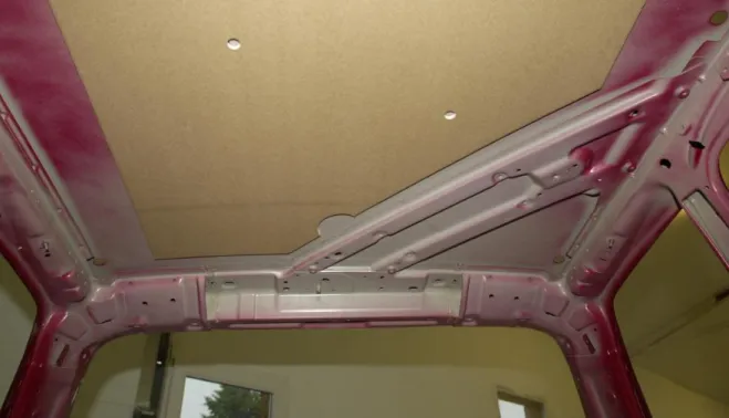
Figure 6: 2010 Volkswagen Sharan Body interior roof view and rail guide
representation. (Volkswagen AG)
2.2 - Premises
One of the most important steps, when it is doing a project in cooperation with a big group as Volkswagen AG, it to clarify since the beginning which are the top premises, not only to use as guidelines during all the process as well as to be sure that no internal or external rules are forgotten.
For this project was established as premises:
New improvements / ideas should be implemented using the Volkswagen AG internal development strategy.
Software used to develop this project must be certified and according Volkswagen AG internal rules.
37
2.3 - Benchmark
As is a Volkswagen goal to be always the best in class, one of the first steps taken was a Benchmark between the most quoted vehicles in market with similar characteristics to Volkswagen Sharan, comparing different concepts actually in production , as well as “pros and cons” of each one.
All the vehicles present in this comparative uses similar materials to them reinforcement as the welding / screw technologies are also similar. This aspect has a particular importance due to the fact that all manufactures tried to use the best design possible to achieve lighter concepts and not the lightest material existent in the market, controlling the development and production costs.
Volkswagen Touran shows a twin concept as the vehicle in study, where there is used a diagonal reinforcement in roof area between the rear cross member and the C-pillar in order to guide the seat belt. Also the fixation point from restraining and D-ring are in similar positions as Sharan. In terms of benchmark for this project it is not a relevant option to analyze because it is basically the same concepts with no new ideas that could be considered as an improvement.
38
Figure 7: Volkswagen Touran second seats row middle seat belt first point fixation.
Following the same line as Volkswagen Sharan and Touran, Ford Galaxy shows a diagonal reinforcement in roof area between the rear cross member and the C-pillar. This variant has the same characteristics as described before, including the fact that it is heavier as the concept presented in this study. As it is possible to see of this component has a minimal engineering design especially in terms of mass reduction. With a simpler design it is not possible to achieve the main goal of this project: reduction of total mass of the vehicle, which makes this option not relevant for this project.
39
Figure 8: Ford Galaxy second seats row middle seat belt first point fixation.
Audi Q7 and Opel Zafira, present a concept where the middle seat from the second seats row has an integrated seat belt. This approach is one of the more beautiful in terms of Design and one of the easiest one to use as final costumer point of view. However in terms of engineering this system obligates to reinforce all the underbody of the vehicle and also all the seat structure must be more robust in order to achieve the requested safety specifications. For this project, where it is supposed to improve an existing concept with the minimum costs possible and also reduce the final mass of the complete vehicle, this concept is not affordable, due to the fact that it would be necessary to redesign and reinforce the entire underbody’s rear area and the complete second row seat structure. Automatically the investment costs would be higher as programmed as well as the total vehicle’s mass.
40
Figure 9: Second seats row from an Audi Q7. (Audi AG)
Ford Grand C-Max, which is a direct concurrent from Volkswagen Sharan, it was choose to use a concept where the seat belt come directly from the C-pillar helped by a small welded reinforcement, as described on Figure 10. Due to design and ergonomic restrictions, this variant needs to have an asymmetric headlining because the seat belt would be available on the left side of the roof area, however and as well as Volkswagen Sharan, it seems to be user friendly.
In an engineering optic, this is one of the best concepts present in this benchmark. The reinforcement used is very simple to perform, safe as requested and also with a top lightweight design.
For this project, and as possible to see in the point 2.4 Constraining, this concept could not be applied, due to the fact that it would be necessary to change several Body
41
structure components, as well as some plastic items in order to use it. Also the interior design of the vehicle must be completely changed. All these modifications would highly increase the final price necessary to its implementation and it wouldn’t be profitable.
Figure 10: Second row middle seat’s seat belt fixation concept from Ford Grand
C-Max.
An also direct concurrent is Mazda 5, where the choose concept is in line with Ford one of the bests present in this Benchmark. Looking to the Design point of view, this variant needs also to have an asymmetric headlining like Grand C-Max.
Regarding engineering and comparing directly to Ford’s concept, in Mazda the philosophy is almost the same with a small reinforcement in the rear quarter window area, however in this case it is not welded to the Body structure but it is screwed after paint. The reinforcement used is also simple, small and safe but this concept shows to
42
be more expensive and possibly heavier due to that it is necessary to use additionally two screws and two nuts to fix the part.
For this project it would be not feasible to use this concept regarding the same aspects as described before to Ford Grand C-Max.
Figure 11: Second row middle seat’s seat belt fixation concept from Mazda 5.
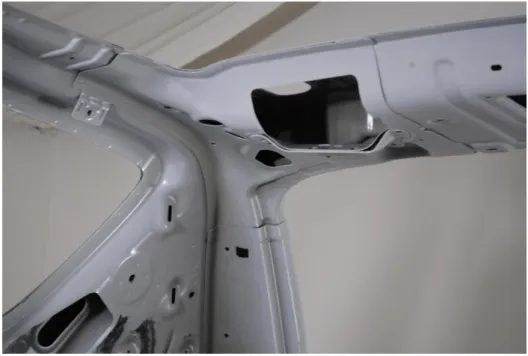
Opel Meriva presents the best concept studied in this Benchmark. Also like Ford and Mazda the interior Design must be asymmetric and also the ergonomic is not the best aspect in this variant due to the fact that the seat belt is not nearby the passenger; however in terms of engineering design this is the simpler, cheaper and lighter concept. In this case Opel chose to use a “hole” in the rear roof cross member. This area is already reinforced, because is a crucial structural area of the vehicle. With this it is not necessary to increase the vehicle’s costs and mass with additional parts in order to achieve the same safety results as the other concurrent.
43
However for this project it would be not feasible to use this concept not only regarding the financial aspects presented on Ford Grand C-Max and Mazda 5 situations, but also because Volkswagen Sharan is a B class MPV, bigger than Opel Meriva that is A-class vehicle. These aspects would make not possible the use the third row right seat when the second row middle seat is occupied, due to the necessary angle to the seat belt.
Figure 12: Second row middle seat’s seat belt fixation concept from Opel Meriva.
Nissan Qashqai adopted a similar situation as Opel, using the area from rear cross member to fix the seat belt. In terms of benchmark the “pros and cons” are exactly the same as the previous model, and for this particular project, it would not be feasible to implement.
44
Figure 13: Second row middle seat’s seat belt fixation concept from Nissan Qashqai.
2.4 - Constraints
Even trying to have the best possible result in mass and price improvement, there are several constrains that should be considered before starting to analyze or design the improved part.
2.4.1 – Design Constraints
Exterior and interior Design is a top premise in order to have a more attractive vehicle to the costumer and consequently increase the sales, all the small details are extremely important.
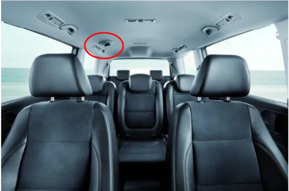
Figure 14 shows the interior of the 2010 Volkwagen Sharan. All the details where taking in account in order to offer a robust and beautiful vehicle for all the
45
family, offering also the entire main item in the correct place concerning to ergonomic and a “user-friendly” perspective.
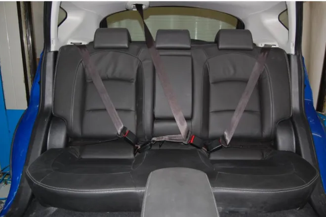
Figure 14: 2010 Volkswagen Sharan interior seats perspective with particular attention
to the second seat row middle seat belt. (Volkswagen AG)
Taking a special attention to the Figure 14, the second seat row middle seat belt has not the best possible design, however its position guarantee the most effective safety to the passengers as well as offers one of the best ergonomic solutions in the market.
46
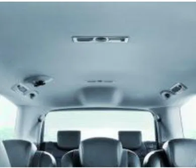
As it is possible to visualize in the Figure 15, the seat belt roller is placed on the upper area from the center of the vehicle between both seats on the third row inside the headlining “bubble”.
Figure 15: 2010 Volkswagen Sharan interior seats perspective, with special detail to the
“bubble” where is located the seat belt retractor. (Volkswagen AG)
Considering a relevant change in the actual concept, it would be necessary to replace the actual “bubble” to one of the sides, which would create a not harmonic design in the vehicles interior and consequently it will be against the “Anmutungphilosophie” (passion to the detail) from Volkswagen’s Group.
47
2.4.2 – Body Constraints
Analysing now the Body structure and the influence of a possible geometry improvement in the rail guide, all significant new design would request changes on some connected components and automatically higher investment costs.
Figure 16: 2010 Volkswagen Body Structure. (Volkswagen AG)
As described before, the part in study connect rear cross member to C-pillar reinforcement. In order to keep these components unchanged, the connection points and contact areas must be kept, if not and as presented on Figure 17 and Figure 18, the marked areas should be redesign in order to be adapted to the improved geometry.
48
Figure 17: Connection between rail guide and rear cross member.
49
Also and as refereed before, the roof has a contact support area to the rail guide. If the improved design takes the same concept as for example Opel Meriva, the contact area will disappear and automatically would be necessary to develop another support mechanism. This situation would imply high investment and creation of new parts, which could increase the vehicle mass.
Other approach to take in mind is a change from actual part’s serial material, where instead of traditional steel; it would be possible to use a lightweight material like aluminum or high resistance composite.
High resistance composite could have the necessary characteristics regarding safety but are not feasible to use in a vehicle of this segment. The investment costs are not possible to support and also the price pro part is also over budget, which would also increase significantly the final price of the vehicle.
Regarding materials like aluminum, it could be more feasible to use. Even though investment is higher than normal steel, this variant is acceptable for this segment and the price pro part could be also absorbed in the final price of vehicle. This is clearly a way to explore, however in this project, where Volkswagen Sharan is a serial vehicle, it would be necessary to change the entire fixations concept from this component to the Body structure and automatically the current production process.
As known, it is not possible to weld aluminum to normal steel, it is necessary to rivet them to a steel structure or use high resistance structural glue. Regarding these restrictions, and as referred before it would be necessary to redesign the entire fixation concept and automatically, change all the construction line regarding this area of the vehicle.
Consequently this situation would request a high investment cost, which is not profitable to this project. However, this is one of the best options in order to have a lightweight vehicle with a reasonable price for these types of segments, and to prove
50
that, brands like AUDI have already some vehicles like Audi A2 / A6 / A8 / Q7 and TT, developed with aluminum parts.
2.4.3 - Trim Constraining
Considering in this case all the final assembly or vulgarly called, Trim parts, any major change in the component in study will affect other critical parts, which could force to redesign them.
Figure 19: Volkswagen Sharan virtual representation from Body structure with Trim
51
Figure 20: Virtual representation from C-Pillar with Trim parts involved in constraints.
Figure 21: Virtual representation from rear cross member with Trim parts involved in
constraints.
Taking a careful look to the three main areas of the rail guide presented in the pictures above, it is possible to visualize that this body part is surrounded by all the main roof Trim parts.
52
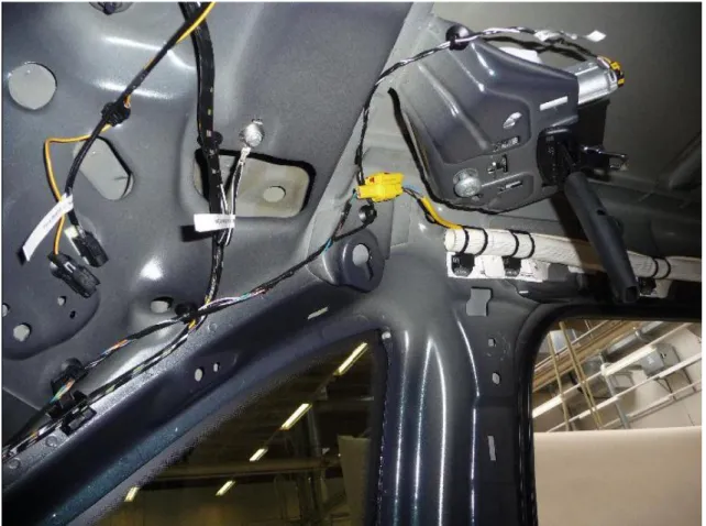
Starting to analyze the first connection point in the C-pillar upper area (Figure 20), the rail guide has the entire rear seat’s airbag system, the air conditional channels, the sliding door upper system, the open roof system and also not directly to the rail roof system nearby.
In order to change the guide rail, it would be necessary redesign all that systems, which means a huge investment, that would not be possible to recover by an improvement on the rail guide.
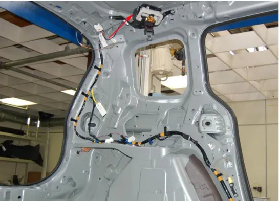
Regarding the second main section, where the rail guide is welded to the rear roof cross member (Figure 21), the problematic is similar as described before.
Despite of there are less parts to be changed, there are some other problems that could not be perceptible at a first view.
This vehicle has a very big interior volume which means that in a first instance it is more difficult to have an optimal air circulation inside the vehicle. However and due to mass distribution and reduction on the vehicle, there is only one air condition pump located on the right side of the vehicle; each means that in order to have the same air flow to all passengers the air conditional channel must have a specific geometry and design. If the rail guide changes its geometry in the rear area, all these channels must be redesign in other to guarantee the same air flow, which means one more time, a dramatic investment.
Analyzing now the part itself and all the components that are directly fixed to it (Figure 22), there are 2 constrains.
53
Figure 22: Rail Guide with seat belt assembled.
It is necessary to fix the seatbelt and due to this, the middle area of the rail guide (area A Figure 22) must but large enough in order to have some free space and let the belt to move without any restrictions.
Second point are the 2 little guides that are fixed to the part in study, which are used to give some pre-tension to the seat belt and also help to fix it in a case of impact.
Due to this situation, if the 4 fixation (area B Figure 22) holes changed, it would be necessary to change also the geometry of those guides.
A
54
3
Characteristics of the part in actual
production
Abstract: In this chapter, it is described with maximum detail all aspects regarding actual
part characteristics, starting with material properties, stamping production process and welding processes not only used to produce the guide rail as a complete group of parts as well as to implement it in the complete Body structure. Processes like cold stamping and projection and spot weld welding, are technically described in order to have a better understanding about their basic functions.
3.1 - Introduction
The Body part in study is currently produced by the company Gestamp Portugal – Gestão e Industria de estampagens metálica, Lda in Aveiro, Portugal, which is owned by an international group dedicated to develop and produce metallic components to Automobile Industry. Actually, Gestamp Group is operational in 18 different countries, with 60 plants and 13 development centers, employing more than 13200 people.
In this chapter will be study all the actual part characteristics, taking special attention to material, actual stamping and welding process not only in the part but also in the complete Body structure.
This chapter is largely based on Simech Simulation et Technologie (2001). Introduction to Sheet Metal Forming Processes. Paris, France.; Dayton Progress Corporation (2003). Stamping Basics Fundamentals & Terminology. Ohio, USA, as well as on Ruukki. Resistance Welding Manual. Helsinki, Finland.
55
3.2 - Material Properties
The component in study is made of high-strength low-alloy steel (HSLA) for cold forming HC340LA according to the standard DIN EN 10268:2006 - Cold rolled steel flat products with high yield strength for cold forming.
HSLA steels is a type of alloy steel that, comparing to common carbon ones, provides better mechanical properties and greater corrosion resistance, thus allowing advantages in terms of reduced component thickness and mass.
The HSLA steel HC340LA used in the construction of part in study has the following chemical composition (DIN EN 10268:2006):
Table 1: Chemical composition in % of grade from the low alloy steel HC340LA.
C Si Mn P S Nb Ti Al
max 0.1 max 0.5 max 1.1 max 0.025 max 0.025 max 0.09 max 0.15 min 0.015
The low alloy steel HC340LA has the following mechanical characteristics (DIN EN
10268:2006):
Tensile strength: 400-500 MPa
0.2% proof strength: 340-410 MPa
Minimum elongation Lo = 80 mm: 22%
Table 2: International equivalent grades from the low alloy steel HC340LA.
USA - Germany DIN, WNr Japan JIS France AFNOR Gr.50 ZStE340 SPFC490 E315C
The HSLA chemical composition is tuned for providing the required mechanical properties. The percent of carbon is kept between 0.05 to 0.25%.
Small amounts of other alloy elements (therefore the “low-alloy” designation) such as copper, nickel, niobium, nitrogen, vanadium, chromium, molybdenium,
56
titanium, calcium and rare earth elements, are added to control the microstructure and grain size, and to improve corrosion resistance.
The use of In case of copper, titanium, vanadium and niobium, provides a decrease in grain size in a ferrite-pearlite microstructure, and a consequent increase in yield strength. Normally yield strength between 250-590 MPa can be achieved.
Although the increase yield strength allows a thickness reduction, usually the manufacturing conforming processes would require 25-30% more power than for normal carbon steels.
Regarding silicon, nickel, chromium and phosphorus, they are added to increase corrosion resistance, on the other hand zirconium, calcium and rare earth elements are added to increase formability properties.
With small variations in the percentages of the alloy elements the steel can meet requirements according to the following classification:
Weathering steels, which have better corrosion resistance.
Control-rolled steels or hot-rolled steels, which have a highly deformed austenite structure that will transform to a very fine equiaxed ferrite structure after cooling.
Pearlite-reduced steels, which have a low carbon content and also residual or no pearlite, but rather a very fine grain ferrite matrix. This type is strengthened by precipitation hardening.
Acicular ferrite steels, which are characterized by a very fine high strength acicular ferrite structure with a very low carbon content and good hardenability.
Dual-phase steels, which have a ferrite microstructure that contains small, uniformly distributed sections of martensite. This microstructure gives low yield strength, high rate of work hardening and good formability.
Microalloyed steels, which contains a small addition of niobium, vanadium and /or titanium to obtain a refined grain size and/or precipitation hardening.
57
Due to the good strength-to-mass ratio and corrosion resistance, this type of steels is used in vehicles manufacturing, cranes, bridges, roller coasters and other structures.
3.3 - Metal Parts Cold Forming Stamping Process
The Body part in study as said before is made by HC340LA steel and in its production it is used the popular cold forming stamping process.
This kind of process is easy to use and allow automobile industry to have high resistance metal parts with the cheapest price as possible, considering also, the high initial investment necessary to implement a new press and the necessary tools, which could be absorbed by the total volume of parts produced. Mainly advantages from this kind of process are:
Stamping production efficiency, easy to operate, easy to implement mechanization and automation.
High accuracy regarding size and shape and good surface quality
Longer life of the dies
Smooth material feeding, product removal and scrap disposal
In order to have a better understanding regarding this kind of technology, it is important to have a short description about the main characteristics of this process:
In 1985, the development cycle of a stamped part looked like more a mess to a sequential series of operations starting with a single style design, which had a 42 months lead time starting with the product design.
58
Nowadays, the perspective is completely different, where key decisions are taken regarding different factors and alternative choices, always with the maximum efficient production as possible. In order to help companies to reduce investment costs with necessary manpower and physical tests, Computer Aided Engineering, usually known as CAE, which allows higher information transfer and process simulations, are used. This computer simulation processes are considered as rough real simulations to have the first approach of the developed component with a smaller investment and also with a smaller lead time, due to the fact that it is not necessary to produce prototype parts to use in tests at this phase. Also these kinds of tests give already great feasibility results in order to proceed with the project.
Figure 24: Nowadays development cycle of a stamped part tool.
Regarding stamping process, it is possible to say that it is, like all complex systems, composed by hardware and software.
In the Hardware group, it is included in this group all the characteristics that cannot be changed from one operation to another. On the other hand, Software is all the characteristics that are changeable from one operation to another in order to have the requested part.
59
Table 3: Components of a stamping design
Hardware Software Press Tools Press set-up Material Lubrication
Considering the Stamping process, the first Hardware part to analyze is the stamping press, which is a machine that houses the stamping tools (tooling) and carries them around according to the kinematics indicated by the user (process set-up) (INTRODUCTION TO SHEET METAL FORMING PROCESSES, Simtech, 2009).
Understanding the stamping press that would be used to a specific operation can provide some important information regarding:
Value and distribution of restraining forces
Tool deformation caused by stamping forces
Contact and/or gap between tools and blank
Although, in many cases during the die design, the stamping press where this specific die will be used is not known. With that not only the design process should be robust enough to be implemented in a larger range of presses.
60
Figure 25: Schematic of a stamping press and diferent dies / operation used to have a
formed part. (Simtech, 2009)
Getting deaper in the understanding of a stamping tool, it is useful to analyze the called Process Design which is “the ensemble of operations leading from the design geometry to the dieface” (Simtech, 2009).
Figure 26: Schematic of a stamping tool. (Simtech, 2009)
As described in “Introduction to Sheet Metal Forming Process, Simtech, 2009”, a stamping tool can be divided in the following main parts: