REF: A0322.0314
DESIGN OF GLASS ARTIFACTS THROUGH RAPID PROTOTYPING
AND RAPID TOOLING
Acácio Silva1, F. Jorge Lino1, and Rui J. Neto2
1
FEUP-Faculdade de Engenharia, Universidade do Porto, Portugal
2
INEG-Instituto de Engenharia Mecânica e Gestão Industrial, Leça do Balio, Portugal Email: (*)[email protected]
SYNOPSIS
The actual competition environment characterized by fast variations and consumer’s sharp necessity in aesthetic satisfaction demands a constant adaptation of the companies, at the development and production levels.
The production of decorating glass parts by thermoforming, with three-dimensional shapes, demands expensive moulds. The complexity associated to the manufacture of these moulds by traditional methods represents a substantial aggravation in price and development time of the final product, makes their production not attractive.
The present work presents adequate methodologies for glass artefacts production by thermoforming, which are based on rapid prototyping models and ceramic moulds hardened by a sol-gel reaction (indirect rapid tooling process). This technology allows the reduction in the time to market and opens new opportunities in the design of new and bold artefacts.
INTRODUCTION
Develop new products is a key process for competitivity in manufacturing industries. The fast technological changes, the reduced product life cycle, the increased product complexity and the pronounced necessity by the consumers in aesthetic, functional and emotional satisfaction, associated to high global level standards, puts the companies under a growing pressure to change their positioning facing the competition. This demands a continuous adaptation towards the acquisition of an increased agility, associated to high productivity and quality, with a strong bet to improve the range of existing products or creation of new ones. Obviously, this necessarily depends on the process efficiency and effectiveness and on the conception and development product system.
The use of the new rapid prototyping (RP) technologies through CAD files coming from conception products systems is increasingly more demanded, due to the answer capacity in short period of time, and the fact that they allow a more detailed analysis of the product, avoiding errors, that if detected in a later phase of the product development cycle could be more onerous.
This communication aims to develop adequate methodologies for production thermoformed glass objects; starting from rapid prototyping parts and ceramic moulds hardened by a sol gel reaction, allowing a greater design freedom and shapes control, as well as a reduced time to market.
The decorative flat glass transformation industries by the thermoforming process are facing themselves with a constant limitation concerning three-dimensional shapes. This derives from
the necessity to produce complex moulds by conventional methods, representing a substantial price aggravation and development time of the new products.
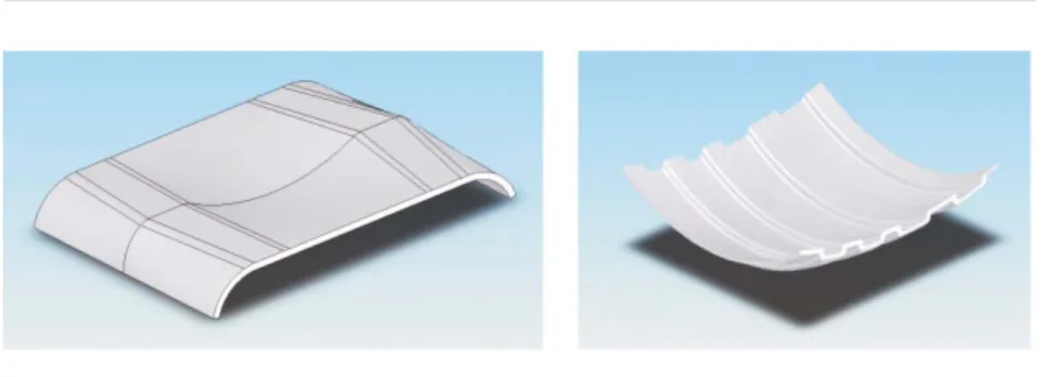
Considering the problem above identified, a methodology based on the design of two small parts, with features that were reproduced in a ceramic mould but that are of considerable difficulty and time consuming to be generated by the conventional methods, was adopted. This way, two prototypes and the respective ceramic moulds were designed in a CAD program (see figs. 1 and 2), keeping in mind the fact that they should be materialised through RP processes and that the glass parts are obtained by thermoforming, with three-dimensional geometries that allow a better evaluation of the process, as well as the possibility of experimenting different glass types, finishing, materials inclusion, and decorative motifs (during and after the thermoforming process).
EXPERIMENTAL
Two different RP processes, LOM and SL, and one indirect rapid tooling process were employed for glass prototypes production.
Mould production using Rapid Prototyping processes
After the creative concepts development phase, the parts and moulds were 3D designed in the software for parametric solid modelling SolidWorks, as shown in figs. 1 and 2.
Fig. 1. CAD design of part 1 (on left) and part 2 (on right) to be produced by the glass thermoforming process.
Fig. 2. 3D modelling of the ceramic moulds for glass thermoforming.
The second phase of the process was the conversion of the 3D modelling files into STL files, to be recognized and processed by the RP equipment. This way, the RP models can be obtained and the respective ceramic thermoforming production tools manufactured.
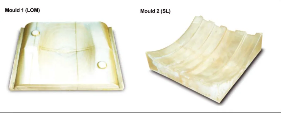
The LOM process produced the mould 1 of fig. 3. After removing the paper material in excess (decubing) from the RP process, and the respective finishing operations, which include grinding and polishing, infiltration with an epoxy resin (increases the resistance of the part and assures impermeablization), the mould was ready for the next stage.
The mould 2 (fig. 3) was manufactured in resin by the stereolitography process (SL). After finishing the prototype construction in the SL machine, the part was polished with polishing paste to eliminate the staircase effect resulting from the RP process, and a smooth and homogenous surface was obtained. In this mould, a special attention was dedicated to the surface finishing, due to fact that in the first mould (LOM) all the surface irregularities were transmitted to the ceramic and consequently to the final glass part.
Fig. 3. LOM and SL moulds after finishing operations.
Negative of the mould in silicone
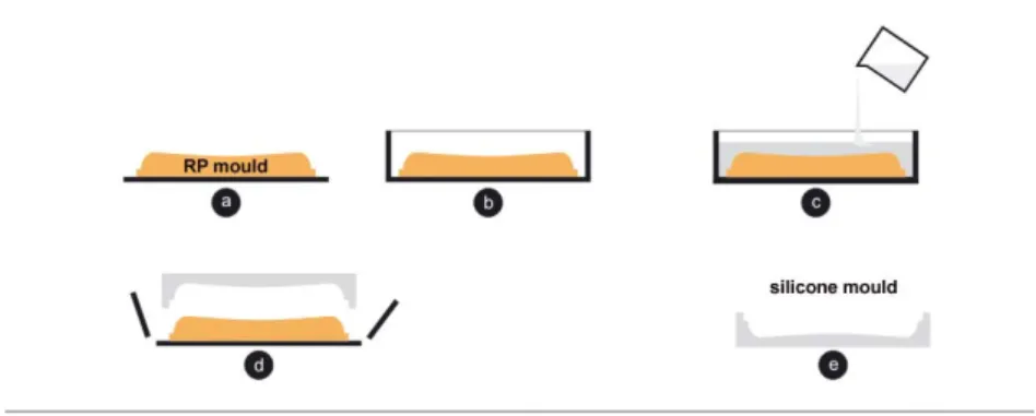
The negatives models of the RP moulds were manufactured in silicone. This process involved the following phases illustrated on fig. 4:
• Cleaning the surfaces of the mould. The part has to be manipulated very carefully, avoiding dirt, such as powder and excess of resin, to assure the better surface finishing;
• Construction of the box to cast silicone (fig. 4a and b). This box is made of wood plates joined with moulding paste, which were used to facilitate the demoulding phase. The mould box has the minimum recommended dimensions for this type of model; • Preparation of the silicone by mixing 100 parts in weight of Silastic T-4 and 10 parts
of catalyst Silastic T-4 (Dow Corning). The mixture was then cast (fig. 4c) and placed in a vacuum chamber to release the gas bubbles introduced during the mixing process; • After a 2h-drying period in an oven at 50ºC, the model was demoulded (fig. 4d). This
operation should be performed very carefully to avoid the damaging the silicone surface. The negative silicone moulds are then obtained, as shown in fig. 5.
Fig. 4. Sequence of steps to obtain a negative silicone mould.
Fig. 5. Negative silicone moulds.
Ceramic moulding
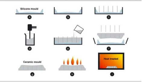
The ceramic moulds were obtained by casting a ceramic slurry over the negative silicone moulds. The ceramic manufacturing process was divided in the following stages (fig. 6):
• Manufacture of an acrylic box surrounding the silicone mould (fig. 6a and b);
• Place 4mm diameter plastic tubes on the surface of silicone (fig. 6c). These tubes produce small holes in the ceramic moulds, which are fundamental to release air and gas produced in the thermoforming process;
• The ceramic slurry is prepared by mixing refractory ceramic particles of different mesh and composition with a binder (hydrolysed ethyl silicate) and a catalyst (ammonia hydroxide). The composition of this mixture was developed by some of the authors (Lino, 2004), and includes a good proportion of fine particles, essentially to reproduce the thin details, and coarse particles, to give resistance to the ceramic mould. Table 1 presents the ceramic mixture composition;
• The slurry (ceramic, binder and catalyst) is cast into the box containing the silicone mould (fig. 6e). After 5-7 minutes, the ceramic acquires a rubbery consistency adequate for demoulding;
• After carefully removing the silicone, the gelation reaction is interrupted by spraying ethyl alcohol over the ceramic mould, followed by burning (fig. 6g and h);
• The ceramic mould is then heat treated (fig. 6i) at 1050ºC for 2 hours, in accordance with the cycle presented in fig. 7 (details of this process can be find on Duarte, 2004).
• The ceramic mould is then painted, using a spray gun, with a releasing agent for the thermoforming process, boron nitride (Rath – Kerathin Coating C BN) (Chua, 2003; ASM, 1991). Fig. 8 shows the final ceramic moulds obtained.
Fig. 6. Sequence of steps to produce the ceramic moulds.
Table 1. Ceramic slurry composition.
Material Amount
Ethyl silicate 1 part to 7,5 (in weight) of the ceramic
Zirconium silicate 325 Mesh 15%
Zirconium silicate 200 Mesh 40%
Zirconium silicate 110 Mesh 15%
Aluminium silicate 30/80 10%
Aluminium silicate 50/80 10%
Aluminium silicate 15/30 10%
Catalyst (ammonium hydroxide in 2,5 % concentration) 1,8% of weight of ethyl silicate
Fig. 8. Final ceramic moulds.
Thermoforming
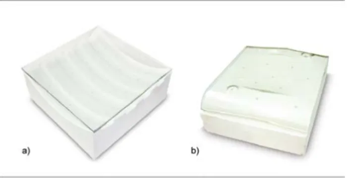
The glass thermoforming was performed on the exterior surface of the ceramic moulds, using the following stages:
• Place the glass over the mould (fig. 9). In the case of glass parts with decorative motifs, they were placed between two glass plates; the glass plate in contact with the ceramic mould has 4 mm thickness and the one on top 2 mm.
• The assembling was placed into the furnace, and submitted to the thermoforming cycle of fig. 10. During the cooling, when the temperature reaches 550ºC, the furnace is turned off and the set cooled inside until the room temperature is reached.
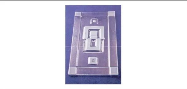
Fig. 9. a) Ceramic mould with the glass on top; b) thermoformed glass part over the ceramic mould.
RESULTS
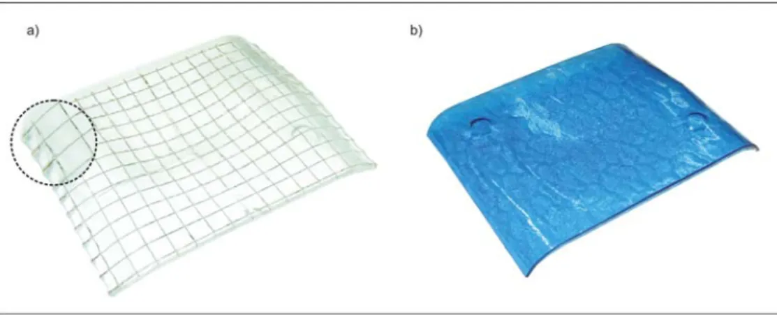
Figs. 9b, 11 and 12 show the final parts obtained. Fig. 11 presents the same part obtained with different types of glass. Wired glass (fig. 11a) did not adapt conveniently to the desired shape (some glass flux left the steel wire uncovered on the sides, a thinner steel wire net should be employed). Coloured and textured glass gave good results, masking some mould surface imperfections.
The rounded saliencies on the two parts were produced seeking the analysis of the glass behaviour facing these two topography details. As one can see, they are perfectly reproduced.
Fig. 11. Parts obtained with different glass types (part 1).
Fig. 12. Part 2 in glass thermoformed.
Glass finishing
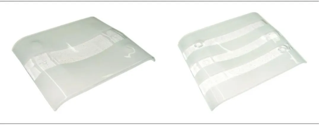
Some of the parts were finished and hand decorated by sand blasting, white Corindon 24 (Coniex), with a spray gun jet on one or both glass surfaces. Different masks (glue tape on the surface) were employed to shade the glass. Fig. 13 presents two of the parts produced, revealing interesting features and the possibility to obtain a large variety of aesthetic effects, which can be explored to introduce, at low cost, company logos or other marketing subjects. Fig. 14 shows the final effect of one part where masks were placed on both sides of the glass. These masks gave the part a shaded effect, presenting on the same side different textures.
Fig. 13. Decorated parts by sand blasting.
Fig. 14. Decorated parts by sand blasting on both sides of the glass.
Decorative motifs
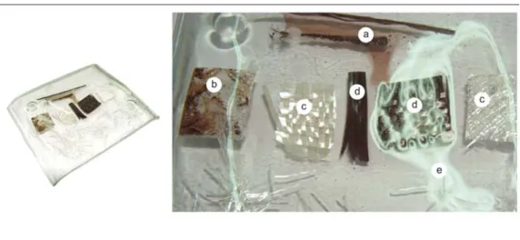
Some parts were produced with the inclusion, between the glass plates, of motifs in different materials. The tested materials were the aluminium foil and glass, carbon and Kevlar fibres. Fig. 15 shows some of the effects obtained. It should be mentioned that the Kevlar did not withstand the temperatures reached on the thermoforming cycle (disappeared, lefting a dark stain). The aluminium foil (fig. 15b) presents some burned regions, and did not result in the desired effect. Glass and carbon fibres (fig. 15c and d) gave interesting effects, and did not present any signs of change in their visual properties. Fig. 15e shows white spots that are gas bubbles between the two plates. In this work it was considered that these bubbles had small importance on the desired aesthetic effect, but it must be considered in future experiences. Fig. 16 shows some parts where glass sheets or bands were used. Interesting aesthetic effects were obtained that should be explored with other materials.
The parts obtained have shown that is still possible to test a great variety of materials for decorative purposes, such as pigments, metals or alloys (copper and its alloys, silver, gold, etc.) in their natural state or in wrought products such as net, wire, powder, etc. Organic materials can also be employed, such as vegetables, that although carbonised during the heating cycle, can leave a track that conveniently explored can be revealed of a great aesthetic importance (Beveridge, 2004).
Fig. 15. Thermoformed part and detail of the inclusion of decorative motifs; a) Kevlar fibres, b) aluminium foil, c) glass fibres, d) carbon fibres, and e) gas bubbles.
Fig. 16. Parts with inclusion of decorative carbon fibres motifs; a) two glass plates of the same size; b) two glass plates of different sizes.
CONCLUSIONS
The main problem found in this work was the inadequate surface quality of the RP models for thermoforming, which present a surface finishing with some roughness.
LOM model was the one with worse finishing, which is in accordance with what is referred in the literature for this process (Lino, 2000; Grimm, 2004). This roughness of the RP processes (staircase effect) are transmitted to the silicone mould and consequently to the ceramic mould (tool). This means that it is necessary to spend some time in the finishing operations of the models, to assure that in the end of the process, the glass thermoformed surfaces, which were in contact with the mould, did not present any signs of these imperfections.
Although some roughness was detected on the glass part obtained from the SL prototype, the surface finishing is superior to the LOM and significantly better to the one obtained with conventional moulds in ceramic fibres, which give the parts a deep texture, as can easily be seen on fig. 17.
Fig. 17. Example of one part obtained with one mould of ceramic fibres.
The main advantage of the thermoforming process presented in this communication lies on the freedom of exploring the potentialities of electronically generate three-dimensional glass shapes that can be materialized with ceramic moulds, and that are very complicated (or impossible) and expensive to obtain using conventional techniques (machining metal blocks, deep drawing steel plates, cut ceramic fibres, etc.).
Finally, the results obtained have shown that with extra research work on the development of composite moulds that use a silicone skin and a low cost filling material, more economic ceramic moulds can be obtained. This way, the global cost of this process can significantly be reduced, turning this process even more attractive for the design of new bold glass parts.
REFERENCES
ASM. Ceramics and Glasses, Engineered Materials Handbook, Vol. 4, 1991.
Beveridge, P., Doménech, and I., Pascual, E. O vidro, técnicas de trabalho de forno, Colecção Artes e Ofícios; Editorial Estampa, 2004.
Chua, C. K., Leong, K. F., and Lim, C. S. Rapid prototyping, principles and applications, 2nd
Ed., World Scientific, 2003.
Duarte, T. P., Lino, F. J., Magalhães, A. B., Neto, R. J., and Ferreira, J. M. Conversion of rapid prototyping models into metallic tools by ceramic moulding – an indirect rapid tooling process, International Journal of Materials and Product Technology, Vol. 21, 4, 2004, p. 317-330.
Grimm, T. User´s guide to rapid prototyping, Society of Manufacturing Engineers, USA, 2004.
Lino, F. J., Neto, R. J., Vasconcelos, P. V., Vasconcelos, M. T., Pereira, A. V., and Silva, E C., Diluição de fronteiras entre o design e a indústria através da prototipagem rápida - um caso de estudo”, Cadernos Empresariais, Ano 2, 7, 2000, p. 58-63.
Lino, F. J., Braga, F. J., Simão, M. S., Neto, R. J., and Duarte, T. M. Protoclick - prototipagem rápida, Porto, 2001.
Lino, F. J., Vasconcelos, P. V., and Neto, R. J. Rapid tooling for plastic injection moulding
using indirect rapid tooling processes, Proceedings of the 13th International Conference on
Processing and Fabrication of Advanced Materials, PFAM XIII, Singapore, 6-8 December 2004.
Vasconcelos, M. T., Vasconcelos P. V., Lino, F. J., Neto, R. J. As sinergias da prototipagem rápida e da internet para um design optimizado”, Use(r) Design, Tema 2: Valores, Lisboa, 2003.
Wohlers, T. Rapid prototyping, tooling, and manufacturing state of the industry, Annual Worldwide Progress Report, USA, 2005.