Faculdade de Engenharia da Universidade do Porto
Cellulose nanofibril-cell adhesive
peptide conjugates for 3D printed
skin tissue model
ANA ELISA SOUSA MORAIS
D
ISSERTATION FOR MASTER DEGREE IN BIOENGINEERINGThesis Project conducted at
3D Bioprinting Center, BBV, Department of Chemistry and Chemical Engineering,
Chalmers University of Technology, Gothenburg, Sweden
Supervisor: Prof. Dr. Paul Gatenholm
Co-supervisor: Dr. Erdem Karabulut
Co-supervisor: Prof. Dr. Pedro Granja
Abstract
The loss of skin can be caused by several reasons, involving intensive hospital care or even months of rehabilitation. Because of several drawbacks of the current treatments, such as risk of immune rejection and lack of donor harvesting sites, novel strategies are required to stimulate skin regeneration. Recent progress in tissue engineering and materials science has enabled 3D printing of biomaterials with living cells and other complementary materials into tissue and organ structures.
Since 3D bioprinting offer advantages on controlled deposition of the cellular and hydrogel components of the bioink, initial studies were dedicated to the development of the hydrogel composition. Cellulose nanofibrils (CNFs) were modified with RGD (arginine-glycine-aspartic acid) and GRGDSP (glycine-arginine-glycine-aspartic acid-serine-proline) peptides and mixed with alginate and/or hyaluronic acid, to evaluate printability, mechanical forces and stability of the printed constructs. Results have showed that the printability of the bioinks was improved upon mixing with enzymatic CNF and alginate.
Hydrogel chemical characterization, such as Dynamic Light Scattering (DLS), Fourier Transform Infrared (FTIR) and X-ray Photoelectron Spectroscopy (XPS) was done to assess the modification of the nanocellulose. After developing the right composition of hydrogel, human dermal fibroblasts were incorporated and cell studies performed. The 3D construct architecture was developed to test if it could provide a suitable environment for fibroblast proliferation and adhesion. The effect of the peptide sequence on fibroblast adhesion and TGF-β (transforming growth factor- β) on fibroblast viability and proliferation was also analysed, along with the different bioink compositions. In vitro cell studies performed with 3D printed models showed that the adhesion and viability of fibroblast cells were promoted significantly compared with non-modified bioinks.
Resumo
A perda de pele pode ser causada por diversos motivos, envolvendo cuidados hospitalares intensivos ou até mesmo meses de reabilitação.Tendo em conta as diversas desvantagens dos métodos de tratamento atuais, como por exemplo risco de rejeição imunitária e falta de dadores, novas estratégias são imprescindíveis para promover a regeneração da pele. Devido a progressos significativos nas áreas de engenharia de tecidos e ciência dos materiais, a impressão tri-dimensional (3D) de tecidos ou órgãos, utilizando biomateriais, células e outros materiais complementares, é agora possível.
Uma vez que a impressão 3D oferece vantagens em relação à deposição da componente celulares e hidrogel da bioink, estudos iniciais foram dedicados ao desenvolvimento da composição do hidrogel. Nanofibras de celulose (CNFs) foram modificadas com sequências peptídicas de arginina-glicina-ácido aspártico (RGD) e glicina-arginina-glicina-ácido aspártico-serina-prolina (GRGDSP) e combinadas com alginato e/ou ácido hialurónico, para avaliação da capacidade de impressão, forças mecânicas e estabilidade das estruturas impressas. Os resultados mostraram que a capacidade de impressão é melhorada quando é adicionado CNF enzimática e alginato.
A caracterização química do hidrogel desenvolvido foi executada através de técnicas como Dynamic Light Scattering (DLS), Fourier Transform Infrared (FTIR) e X-ray Photoelectron Spectroscopy (XPS), com o objetivo de confirmar a modificação da celulose. Após desenvolver a composição certa do hidrogel, foram incorporados fibroblastos de derme humana e procedeu-se aos estudos celulares. A estrutura 3D foi desenvolvida para testar se era capaz de oferecer um ambiente adequado para a proliferação e adesão dos fibroblastos. O efeito da sequência pepítica na adesão de fibroblastos e do factor de crescimento TGF-β
(transforming growth factor- β) na viabilidade e proliferação celular foi também analisada, para todas as composições de bioinks. Estudos celulares in vitro das estruturas 3D impressas,
mostram que a adesão celular e viabilidade dos fibroblastos é significativamente maior quando comparada a estruturas impressas com bioinks não modificadas.
Acknowledgements
First I would like to thank Prof. Paul Gatenholm for giving me the opportunity to work with the BBV team at Chalmers in this project, receiving me with open arms, for his contagious enthusiasm and energy, inspiring ideas, but most of all for his absolute support.
I would like to deeply thank my supervisor Dr. Erdem Karabulut for his guidance on my project, his support through all the steps of it and mostly, for sharing his knowledge on nanocellulose, which I’ll take with me forever. He was always available to help, even with the simplest things. His good mood and energy was easily contagious, so I could not ask for a better supervisor.
All colleagues and friends at BBV: Kajsa, thank you for always being available to help and teach; Elin, thank you for all your help with the cell studies, it would be impossible to do without you; Sandra, thank you for being a friend always ready to help and keeping company since the beginning; Samantha and Thomas, thank you for teaching me so much and to always be ready to laugh; Ida, thanks for teaching me almost all I know about bioprinting and for being such a nice and fun person to hangout with; Michela, for always cheering me up and for helping me feel like home; Héctor, for his contagious good mood and availability to help.
All my friends I met in Gothenburg, thank you for all the support on doing my project, for being such good company and for all your enthusiastic questions and discussions about my work.
To my friends and family back at Portugal, thank you for all the support and kindness. But especially to my parents António and Maria Teresa, for providing me all I needed, giving me the opportunity of a lifetime, and my brother Nuno for all his support and interest in my project.
Table of contents
Abstract ... iii
Resumo ... v
Acknowledgements ... vii
Table of contents ... ix
List of figures ... xi
List of tables ... xiii
Abbreviations ... xv
Objectives ... xvii
Chapter I ... 19
Introduction ... 19
1.1 - Wound healing and skin tissue engineering ... 20
1.2 - Treatment methods of skin lesions ... 22
1.2.1
- Conventional treatments ... 22
1.2.2
- Tissue-engineered skin substitutes ... 23
1.3 - 3D Bioprinting ... 24
1.4 - Bioink components used in 3D Bioprinting ... 25
1.4.1 -
Nanocellulose ... 26
1.4.2
- Alginate ... 26
1.4.3
- Hyaluronic Acid ... 27
1.4.4
- Cell source ... 29
1.5 - RGD and integrin recognition ... 30
Chapter II ... 33
Methodology ... 33
2.1 – CNF bioconjugation ... 33
2.2 – Characterization of inks ... 34
2.2.1 – X-Ray Photoelectron Spectroscopy (XPS) ... 34
2.2.3 – Fourier Transform Infrared Spectroscopy (FTIR) ... 35
2.3 – Bioink formulation ... 35
2.4 – Rheology and printability studies ... 36
2.5 – Cell Source, expansion and harvesting ... 37
2.6 – Overview of cell studies ... 37
2.6.1 – Cell viability ... 37
2.6.2 – Cell morphology ... 38
2.6.3 – Collagen production ... 38
Chapter III ... 40
Results and Discussion ... 40
3.1 - Characterization of inks ... 40
3.1.1 – XPS analysis ... 40
3.1.2 – DLS dispersion analysis ... 40
3.1.3 – FTIR spectra analysis ... 42
3.2 – Rheology Studies ... 42
3.3 – Printability Studies ... 43
3.4 – Cell Viability ... 46
Live/Dead Assay ... 46
Calculation of cell viability ... 48
3.5 – Cell morphology ... 49
Confocal Imaging ... 49
3.6 – Histology ... 55
Van Gieson Staining ... 55
Chapter IV ... 58
Summary and Conclusions ... 58
4.1 – Further experiments and analysis ... 58
References ... 60
List of figures
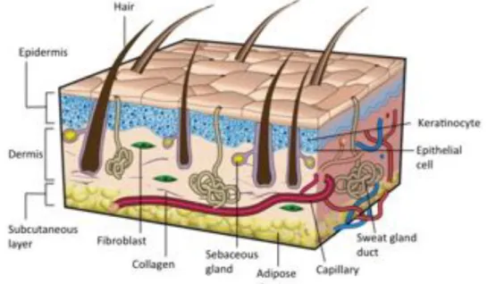
Figure I.1 – Sectional view of the three layers of skin, its appendages and the main
cellular constituents. Adapted from Gurtner et al. [9]. ... 20
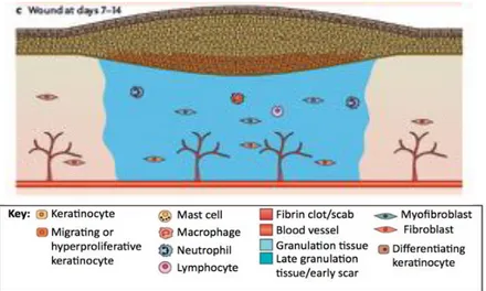
Figure I.2 – The different phases of the wound healing process. (A) Hemostasis and
inflammation phase. A fibrin clot is formed, while at the same time, inflammatory cells (neutrophils, mast cells, macrophages and lymphocytes) are attracted to the wound site. (B) New tissue formation phase. Epithelial cells and fibroblasts migrate into the wound site and synthesize large quantities of ECM components, which prompt the formation of granulation tissue. (C) Maturation and tissue remodeling phase. Wound re-epithelialization is completed and the composition and properties of the granulation tissue are progressively remodeled. From Schäfer et al. [10]. ... 22
Figure I.3 – (A) Structure of the alginate monomers: β-D-mannuronic acid (left) and
α-L-glucuronic acid (right). (B) Egg-box structure of the cross-linking between a divalent cation (Ca2+) and monomers from different chains. Adapted from Pistone et al. [54]. .. 27
Figure I.4 – (A) Structure of the hyaluronic acid monomers: Glucuronic acid (left) and
N-acetylglucosamine (right). (B) Synthesis reaction of hyaluronic acid-tyramine conjugates. (C) Gel formation of a polymeric hydrogel composed of hyaluronic acid-tyramine conjugates by an enzyme-mediated oxidative reaction of acid-tyramine moieties using hydrogen peroxide (H2O2) and horseradish peroxidase (HRP). Adapted from
Kurisawa et al. [63]. ... 29
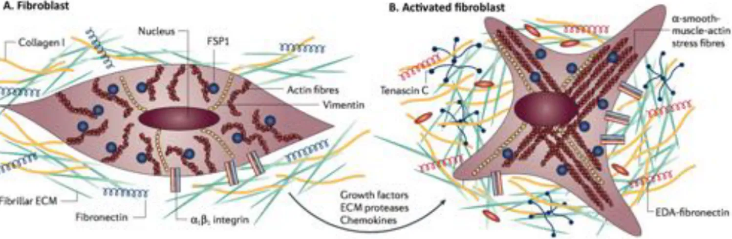
Figure I.5 - Fibroblast activation. (A) At its normal state, fibroblasts are embedded within
the extracellular matrix (ECM), containing large quantities of type I collagen and fibronectin. These cells interact with the unique environment in the vicinity through integrins such as α1 and β1. Usually, fibroblasts appear as fusiform cells
constitutively expressing vimentin and fibroblast-specific protein 1 (FSP1). (B) Fibroblasts can acquire an activated phenotype mainly caused by a range of biochemical stimuli, including growth factors, chemokines and ECM-degrading proteases, which are released by epithelial cells when tissue injury occurs. Activated fibroblasts, usually described as expressing α-smooth muscle actin, are associated with strong proliferative activity and increased secretion of ECM proteins (collagen I, tenascin C and EDA-fibronectin). Adapted from Kalluri et al. [65]. ... 30
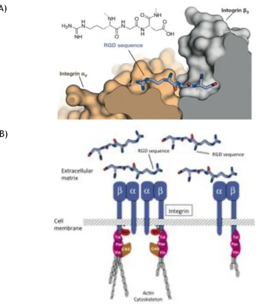
Figure I.6 – RGD-integrin interaction. (A) – Structure of the RGD sequence from
fibronectin bound to the αv (orange) and β3 (grey) integrin subunits. (B) – Schematic
representation of the interaction between integrins and the extracellular matrix molecules (e.g. fibronectin). Adapted from Pelay-Gimeno et al. [80] and Giancotti et al. [81]. ... 31
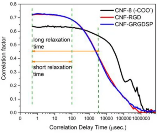
Figure III.1 – Correlation graph determined by DLS of pure carboxymethylated CNF
(black), RGD-modified CNF (red) and GRGDSP-modified CNF (blue). ... 42
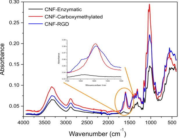
Figure III.2 – FTIR spectra of pure enzymatic CNF (black), carboxymethylated CNF (red)
and RGD-modified CNF (blue). ... 43
Figure III.3 – Viscosity versus shear rate curve for the bioinks developed, comparing with
CELLINK. ... 44
Figure III.4 – Stests performed for the bioink compositions of the pilot experiment using
Inkredible.. ... 44
Figure III.5 – Stests performed for the bioink compositions of the full study using 3D
Discovery. ... 45
Figure III.6 – The pilot experiment bioinks stability is evaluated over 14 days. ... 45
Figure III.7 – The full study bioinks stability is evaluated over 14 days. ... 46
Figure III.8 – Viability of human dermal fibroblasts after 1, 7 and 14 days (magnification
10X). ... 47
Figure III.9 – Comparison of cell viability on day 1, 7 and 14, between CELLINK H and
CELLINK SH. ... 48
Figure III.10 – Comparison of cell viability on day 1 and 7, between CELLINK RC and
CELLINK RCH, supplemented or not with TGF-B. ... 49
Figure III.11 – Fibroblast morphology at day 14 and 23 in CELLINK H and CELLINK
(magnification 20X). ... 50
Figure III.12 – Fibroblast morphology at day 3, before adding TGFB in CELLINK RC and RCH
(magnification 20X). ... 51
Figure III.13 – Fibroblast morphology at day 7, 14 and 23 with presence or not of TGF-β in
CELLINK RC (magnification 20X). ... 52
Figure III.14 – Fibroblast morphology at day 7, 14 and 23 with presence or not of TGF-β in
CELLINK RCH (magnification 20X). ... 54
Figure III.15 – Zoomed in images from CELLINK RCH TGFB Day 23 samples (magnification
20X). ... 55
Figure III.16 – Van Gieson staining for collagen fibers production (magnification 10X). ... 56
Figure III.17 – Human dermal fibroblast morphology at day 14 and 23, for CELLINK RC with
the presence or not of TGFB (magnification 10X). ... 65
Figure III.18 - Human dermal fibroblast morphology at day 14 and 23, for CELLINK RCH
List of tables
Table II.1 — Bionk compositions for pilot experiment. ... 35
Table II.2 — Bionk compositions for full study. ... 36
Table II.3 — Overview of cell studies experiments. ... 39
Table III.1 — Atomic surface concentrations of modified and non-modified nanocelluloses
determined by XPS. ... 40
Table III.2 — Particle size measurement determined by DLS. ... 41
Table III.3 — Zeta potential measurement determined by DLS. ... 41
Abbreviations
3D Three-dimensional
CNF Cellulose Nanofibrils
RGD Arginine-glycine-aspartic acid peptide sequence
GRGDSP Glycine-arginine-glycine-aspartic acid-serine-proline peptide sequence DLS Dynamic Light Scattering
FTIR Fourier Transform Infrared
ESCA Electron Spectroscopy for Chemical Analysis TGF-β Transforming growth factor-β
ECM Extracellular matrix GAG Glycosaminoglycans CAD Computer aided design NCC Nanocrystalline cellulose BNC Bacterial nanocellulose CaCl2 Calcium chloride
HA Hyaluronic acid
Tyr Tyramine
HATyr Hyaluronic acid-tyramine conjugates H2O2 Hydrogen peroxide
HRP Horseradish peroxidase MMP Metalloproteinase
FSP1 Fibroblast-specific protein 1 FGF2 Fibroblast growth factor 2
ICAM1 Intercellular-adhesion molecule 1 VCAM1 Vascular-cell adhesion molecule 1
EDC N-(3-dimethylaminopropyl)-N-ethylcarbodiimide hydrochloride HCl Hydrochloric acid
NHS N-hydroxysuccinimide NaOH Sodium hydroxide
TS-NaHy Tyramine substituted sodium hyaluronate HBSS Hank’s Balanced Salt Solution
DMEM Dulbecco’s Modified Eagle Medium DAPI 4',6-diamidino-2-phenylindole PBS Phosphate-Buffered Saline
Objectives
The overall aim of the thesis is to design and synthesize bioactive bioinks based on cellulose nanofibrils (CNF), capable of promoting adhesion of human dermal fibroblasts, for use in 3D bioprinting with focus on human skin.
In order to accomplish this, different strategies were pursued concerning the following specific aims:
i. To design and prepare, using 3D bioprinting, a construct able to provide a suitable 3D environment for fibroblast proliferation and adhesion.
ii. To chemically modify CNFs with the cell adhesive RGD molecules to regulate human dermal fibroblast attachment.
iii. To evaluate the effect of hyaluronic acid and alginate, along with nanocellulose, on the bioink formulation and its printability.
iv. To study how different bioink compositions can influence human dermal fibroblasts viability, proliferation and attachment.
v. To analyze the effect of the RGD peptide sequences, as functionalization of nanocellulose, on human dermal fibroblast adhesion.
vi. To analyze the effect of TGF-β on human dermal fibroblast proliferation.
vii. To analyze the production of collagen by the human dermal fibroblasts within the construct.
Chapter I
Introduction
Skin is the largest organ in the human body, acting as a protection against external factors, with an exceptional sensory perception and self-renewal capacity. It comprises three different layers, each one with a distinctive composition, structure and function [1,2]. Since it’s extremely exposed to outside factors, skin is prone to suffer lesions, caused especially by chronic wounds, surgical interventions, trauma or burns [3]. However, skin has a natural and dynamic healing process, which results in the reestablishment of anatomic cohesion and function, generating, at the time of injury, a complex cascade of distinct but overlapping events of hemostasis, inflammation, migration, proliferation and remodelling [2].
Current therapeutic approaches rely on the use of wound dressings and auto- or allografts. However, these treatments have some disadvantages; for example, donor site limited availability, healing problems after harvesting or even risk of immune rejection and transmission of diseases [4]. Due to several drawbacks of conventional treatments available to treat skin lesions, it is highly pertinent to develop new ones aimed at promoting skin regeneration. The compelling demand for more suitable treatments has promoted the search for alternative solutions, such as tissue-engineered skin substitutes [2]. But these can’t overcome the poor revascularization or their extremely high production cost [5].
Advanced skin regeneration methods offer an efficient, permanent and applicable alternative to the currently available skin grafts, by surpassing their major downsides, specially the well-organized 3D multilayer skin structure, with an improved vascularization [6]. By using 3D bioprinting technology, skin cells and other components can be delivered uniformly into the wound, along with their correct anatomical configuration, so that the regeneration of the damaged tissue could be improved. At the same time, skin function can be restored without scarring and damaging tissue in the vicinity [7].
1.1 - Wound healing and skin tissue engineering
Skin is the largest organ in the human body, with a total area of 1.8 m2, playing a crucial
role in the protection against external factors, fluid homeostasis, sensory perception, body dehydration, and the wound healing process itself. Skin comprises a thin and highly cellular epidermis, a fairly acellular dermis of collagen-rich extracellular matrix (ECM) and a deeper subcutaneous layer (Fig. I.1) [1,2]. The epidermis is mostly composed of layers of keratinocytes, but also other cell types, as for example melanocytes. Being classified as the outermost barrier of our body, this highly impermeable layer constitutes a barrier against infection and water loss. Below the basement membrane, the dermal layer is essentially composed by the ECM, which is abundant in collagen, elastin and glycosaminoglycans (GAGs). Fibroblasts are the main cell type present in the dermis, regulating its biomechanical activity. This layer provides elasticity and mechanical integrity, as well as strength to the skin, supporting its structure. The hypodermis layer mainly consists of adipose tissue and a layer of connective tissue, along with collagen, functioning as an energy source [8].
Figure I.1 – Sectional view of the three layers of skin, its appendages and the main cellular
constituents. Adapted from Gurtner et al. [9].
Skin has an intricate healing process, generating, at the time of injury, a complex cascade of distinct but overlapping stages of hemostasis, inflammation, migration, proliferation and remodelling. This process is only possible due to the intricate communication and interaction between its key players (e.g. cellular components, biomolecular agents) [2]. After a skin injury, the epidermal barrier is disrupted and the formation of a platelet occlusion and blood clot takes place, resulting in a temporary coverage of the wound. This fibrin clot is an essential step since (i) it works as a shield against external substances and (ii) offers a support matrix for cell migration. Moreover, the clot also comprises a plethora of growth factors, which also participate in the wound closure process. This phenomenon attracts inflammatory cells (i.e. macrophages and neutrophils) to
the wound site, which are essential to protect against invading bacteria. These cells are capable of producing high quantities of growth factors and cytokines, necessary to start proliferation and ECM production by the fibroblasts [10,11].
In the new tissue formation phase, keratinocytes in the wound vicinity migrate and proliferate into the wound, leading to re-epithelialization. Simultaneously, the process of dermis repair is initiated and angiogenesis begins to take place. Afterwards, fibroblasts initiate their migration into the wound, where their proliferation and production of high amounts of ECM is crucial for the formation of granulation tissue [10].
In the final phase, this newly formed granulation tissue suffers matrix remodeling and cellular reduction, being transformed into scar tissue. This tissue is not, at all, similar to healthy tissue, since its mechanical stability, strength and elasticity is greatly reduced, and it lacks skin appendages (Fig. I.2) [10].
Tissue engineering is an emerging interdisciplinary field that links concepts of engineering and life sciences, aiming to develop tissue substitutes, resembling the host tissue environment and capable of promoting tissue regeneration, including the treatment of skin lesions. The purpose of developing biological substitutes, which combine scaffolds, cells and biomolecular signals, is mainly to restore, maintain or even improve tissue functions [6].
In the last few decades, remarkable advances and further understanding in cell and molecular biology have contributed to significant achievements in skin tissue regeneration for wound healing applications [12]. Tissue-engineering’s most accepted and successful strategy so far relies in the cell-matrix construct for skin regeneration, although the challenge remains when trying to translate this complex concept to clinical applications [5].
Figure I.2 – The different phases of the wound healing process. (A) Hemostasis and inflammation phase.
A fibrin clot is formed, while at the same time, inflammatory cells (neutrophils, mast cells, macrophages and lymphocytes) are attracted to the wound site. (B) New tissue formation phase. Epithelial cells and fibroblasts migrate into the wound site and synthesize large quantities of ECM components, which prompt the formation of granulation tissue. (C) Maturation and tissue remodeling phase. Wound re-epithelialization is completed and the composition and properties of the granulation tissue are progressively remodeled. From Schäfer et al. [10].
1.2 - Treatment methods of skin lesions
The loss of skin is caused by several reasons, especially chronic wounds, surgical interventions, trauma or even burn injuries [3]. For instance, in developing countries, burns are a major cause of disability, involving intensive care or even months of rehabilitation, where there are neither the economic capacity nor the necessary infrastructure to set up these tissue-engineered technologies. Throughout the world, 500,000 burns are treated annually, causing healthcare costs of almost 2 billion euros and over 300,000 deaths [13,14]. Patients, who suffer large-scale wounds, damaging a large area of skin, would benefit from quick treatments able to preserve and protect the wound site, but also to restore function of the damaged tissue. Conventional treatments have been developed, but still present some disadvantages [7].
Given the prominent impact of skin lesions, not only socially but also economically, its treatment should be addressed in a thorough and effective manner, so that it helps to reduce costs and improve patient’s quality of life. The treatment of skins lesions depends on parameters like the wound type, the wound depth (epidermal, superficial partial-thickness, deep partial-thickness and full-thickness wounds) and the patient’s health [15]. Nowadays there is a plethora of products and strategies for the treatment of different types of skin lesions.
1.2.1 - Conventional treatments
Autografts are the clinical “gold standard” in skin regeneration treatment, due to their safety and fast-healing process, providing good adhesion to the wound and reduced rejection. The major downside is their low availability, since they can only be retrieved from specific
and limited sites. Since burned patients usually have a compromised immune system and the donor sites may heal with some scarring, which result in discomfort and pain, this constitute a massive challenge in the treatment of skin lesions using this method [4,16].
Allografts are used as a temporary prevention method of fluid loss or contamination, being able to incorporate into profound wounds. They also have limited availability, and may lead to immune rejection and transmission of diseases, which states a major ethical issue, since they are retrieved from donors [4].
Wound dressings are used as a primary approach to cover the wound and provide a protective barrier. Generally speaking, these dressings are widely used in healthcare facilities, due to their low cost, simplicity of use and effectiveness of coverage and protection of the wound site. They can be classified as traditional and modern dressings. The first ones are bandages and gauzes, applied to the wound to absorb great amounts of exudate, which may hinder the wound healing process by not providing a moist environment, representing the most relevant downside. Additionally, by absorbing most of the fluids, they can be difficult to remove, causing discomfort to the patient. Modern dressings were developed to answer the limitations of the traditional ones. These are capable of offering and maintain a moist environment, with the ability, at the same time, to keep the wound hydrated and remove the excess fluids. However, they are more expensive, hard to adhere to the wound site and may also inhibit the healing process [4,17]. Conventional treatments are also associated with an abundant analgesic usage and the already mentioned possible prolonged hospital stay [18].
1.2.2 - Tissue-engineered skin substitutes
Due to several drawbacks of conventional treatments available to treat skin lesions, it is highly pertinent to develop new ones aimed at promoting skin regeneration, by stimulating the inherent ability of the tissue to self-renew. The compelling demand for more suitable treatments has encouraged the search for alternative solutions, such as tissue-engineered skin substitutes [2]. For an “ideal” tissue-engineered skin substitute to be used in vivo, it must satisfy three main requirements; they must be safe for the patient, clinically efficient and easy to handle and apply on the wound [19].
Several tissue engineered skin substitutes are already clinically available. These products can be divided into epidermal, dermal and dermo-epidermal constructs. Epidermal substitutes (e.g. Epicel®, Laserskin®) are used for the treatment of epidermal lesions, by
isolating autologous keratinocytes in vitro, along with a feeder-cell culture of autologous fibroblasts, thus obtaining the required number of keratinocytes for therapeutical needs [19]. Dermal substitutes (e.g. Alloderm®, Karoderm®, Dermagraft®) are essential to regenerate full-
thickness skin wounds, where the dermis cannot be reconstructed by conventional treatments. These substitutes are scaffolds of natural (e.g., collagen and glycosaminoglycans)
or synthetic origin, combined or not with fibroblasts of autologous or heterogeneous origin. Usually, they need to be covered by a permanent autologous split-thickness skin graft [20]. Dermo-epidermal substitutes (e.g. Karoskin®, Apligraf®) are the most advanced and
sophisticated substitutes currently available in the market, since they are able to simulate the histological structure of the skin, by inducing the regeneration of the epidermal and dermal layers. Although they are temporary, due to their cellularized composition, these constructs are claimed to actively release growth factors, cytokines and other ECM components to the host cells, thereby stimulating a more effective regeneration process [21]. Despite the proven clinical benefits of tissue engineered skin substitutes, several significant challenges to overcome still persist in this field, such as extremely high production costs and lack of success to achieve permanent wound closure, insufficient adhesion to the wound, possible presence of scarring at the vicinity, poor revascularization or inexistence of skin appendages (hair follicles, sweat and sebaceous glands) [1,5,22].
1.3 - 3D Bioprinting
Creating biomimetic microenvironments that demonstrate natural tissue structures and properties has always been of great interest in regenerative medicine. Taking this into account, 3D constructs that combine (i) intricate and complex patterning of ECM constituents, (ii) biomolecules, and (iii) cells, have been a main priority [23–25]. However, conventional techniques for production of 3D scaffolds (i.e. electrospinning [26], fiber deposition [27], freeze-drying [28]) are not able to provide proper control of the structure and topology. Moreover, several current 3D scaffolds just allow either a bulk inclusion of biomolecules within the matrix or an external release of these through the medium [29–31]. Thus, innovative scaffold production methods are essential to achieve the precision and consistency of well-distributed 3D microenvironments [7].
Bioprinting is described as an automated layer-by-layer additive manufacturing technique, able to assemble tissue-like structures, with spatial control of their placement and data derived from a digital model. Such method allows the incorporation of cells inside the scaffold during the production of 3D constructs, resulting in a well-distributed pattern [32,33]. The material used in this technique, known as bioink, usually include a thorough combination of living cells, polymers, and biomolecules to create a functional 3D living structure [7]. The digital modelling of the 3D structure is generally done with the help of a computer-aided design (CAD) software, necessary to place the bioink into the accurate geometry, mimicking the natural tissue environment and architecture [34].
A plethora of different bioprinting techniques have been recently explored, such as inkjet printing, extrusion and laser-assisted devices.
Inkjet printing, or drop-by-drop printing, is a non contact bioprinting technique able to deposit controlled and precise volumes of droplets, creating 3D biological structures [35].
This kind of bioprinters use thermal [36] or piezoelectric [37] forces to dispense drops of bioink onto the substrate, usually using a cartridge-based delivery system installed on an XYZ plotting device. The drop-by-drop approach allows for a quick polymerization of the printed material, so that the next layers can be added to the growing structure [7]. Moreover, inkjet printers allow a high printing speed, high resolution, low cost and compatibility with several biological materials. However, these also state some drawbacks, specially the shear stress applied on the cells at the nozzle tip, the small droplet size (not much larger than the diameter of a cell) [38] and the low maximum limit of viscosity of the ink (around 0.1 Pa s-1)
[39].
Extrusion-based bioprinters work by extruding the material through a syringe tip, in a controlled fashion, which is then deposited onto the substrate. This type of printer produces a continuous flow of material instead of liquid droplets. So that the shape of the constructs after printing is maintained, hydrogels with higher viscosity are used, when comparing to inkjet printing. The resolution achieved (around 200 µm) is the lowest between laser- and inkjet-based techniques [40,41]. Altogether, extrusion-based bioprinting is able to produce organized constructs of relevant sizes and within an acceptable time frame [34,42].
Laser-mediated bioprinting system is a technology based on the emission of laser pulses to position the cells of the cell suspension onto the collector surface [43]. This allows for a precise deposition of materials and a high density of cells in 3D structures, without affecting cell viability or function [44,45]. Since it is a nozzle-free technique, it’s not affected by clogging problems, supporting bioinks with a broad range of viscosities (1-300 Pa s-1) [46].
To address the challenge of mimicking the biological and functional organizational complexity of natural tissues, additive manufacturing has been adopted to produce tissue-like 3D structures [47]. Advanced skin regeneration methods offer an efficient, permanent and applicable alternative to the currently available skin grafts, by surpassing their major downsides, specially the well-organized 3D multilayer skin structure, with an improved vascularization. These incorporate live cells, biologically active molecules, biomaterials and advanced fabrication techniques, resembling skin structure and promoting tissue regeneration [6].
1.4 - Bioink components used in 3D Bioprinting
Besides the type of bioprinting technique used, there are other parameters that should be taking into account so that viable and functional tissue constructs are printed. The first variable is the cellular component, which can be composed by one or more cell types and from different sources. The second one, the biomaterial, usually a polymer, is responsible for providing physical and chemical properties to the construct, but also to assist the printing process. Equally important is the maintenance and maturation after the printing process, where bioreactors are often used [7].
An appropriate hydrogel for a certain biofabrication process, i.e. suitable for both printing and cell culture, mainly depends on its composition and properties, which still states a challenge. The use of hydrogels as bioinks offers a resourceful system that is deeply capable of being processed, biocompatible, and easily manipulated in regard of printing 3D constructs. The bioink is usually composed of a mixture of cells, polymers and biomolecules that together determine the properties of the hydrogel.
1.4.1 - Nanocellulose
Cellulose is the most abundant natural polymer, being considered as an almost endless material. In the last few years, nanocellulose has sparked some interest for biomedical applications, because of its unique properties, such as its porosity, mechanical stiffness, chemical-modification capacity, biocompatibility, low toxicity or even its gelling capacity, making it a perfect candidate to be used as bioink. One of the most important characteristics is the fact that this material is able to provide a porous matrix, which is essential for oxygen diffusion and nutrient exchange in the 3D structure [48].
Three different types of cellulose are identified: cellulose nanofibrils (CNF), nanocrystalline cellulose (NCC) and bacterial nanocellulose (BNC). These differ in their preparation method, dimensions, functions and source. [48]. Since CNF is the type of cellulose used in this project, special attention will be given to it.
Cellulose nanofibrils (CNF), with a diameter of 2-3 nm and a length range of 1-3nm are produced by mechanical disintegration of wood fiber wall using a homogenizer at high pressure, along with chemical or enzymatic treatment. It’s previously known that the chemical modification of wood fibers prior to disintegration improves the colloidal stability and decreases the energy consumption due to the introduction of charged functional groups to the nanofibril interface. During this process the fibre size changes from millimetres to nanometers [49].
1.4.2 - Alginate
Alginate is a natural polysaccharide derived from the cell walls of algae. In terms of structure, alginate is a linear copolymer composed of negatively charged blocks of (1,4)-linked β-D-mannuronic acid (M unit) and α-L-glucuronic acid (G unit) (Fig. I.3 (A)). Depending on the source alginate is extracted from, the G/M ratio and distribution can vary, resulting in changes of mechanical strength and dissolution time. Thus, these properties are directly related to the G/M ratio of the hydrogel, stating that a higher G/M content creates a stiffer, with slower dissolution hydrogel [50].
Alginate hydrogels have received great attention and applications in bioprinting have increased, since they are so easily cross-linked. Since their first use to fabricate 3D bioprinted structures by Boland et al. in 2006 [36], to the more recently application in in situ
printing, by Cohen et al. in 2010 [51]. Furthermore, they present other advantages such as, low cost, great availability, good biocompatibility with low inflammatory response and are capable of providing shape fidelity and volume retention both in vitro [52] and in vivo [53].
There are different methods to prepare alginate hydrogels, such as covalent cross-linking, photo cross-linking and the most commonly used, ionic cross-cross-linking, used in this project. In this method, an aqueous solution of sodium alginate is mixed with calcium chloride (CaCl2). Alginate’s negatively charged groups are able to form ionic bonds with
divalent cations (e.g. Ba2+, Sr2+, Ca2+), which link the different alginate chains and act as
cross-linkers [54,55]. This mechanism can be described as the “egg-box model”, where the cations form complexes with G or M monomers in an egg-box shape (Fig. I.3 (B)) [56].
Figure I.3 – (A) Structure of the alginate monomers: β-D-mannuronic acid (left) and α-L-glucuronic acid
(right). (B) Egg-box structure of the cross-linking between a divalent cation (Ca2+) and monomers from
different chains. Adapted from Pistone et al. [54].
1.4.3 - Hyaluronic Acid
Hyaluronic acid (HA), a major component of the extracellular matrix, is an anionic, non-sulphated glycosaminoglycan composed of repeating disaccharide units (β-1,4-D-glucuronic
β-D-mannuronic acid (M)
α-L-glucuronic acid (G)
(A)
acid and β-1,3-N-acetyl-D-glucosamine) (Fig. I.4 (A)) [57]. HA is highly biocompatible, playing a central role in many biological mechanisms through its interaction with cell receptors present in ECM molecules, such as cell signalling, wound repair and matrix organization [58], but also as a structural molecule, providing tissues with desired mechanical properties [59]. Furthermore, HA has been shown to be non-toxic, non-immunogenic and non-inflammatory, making HA-based materials extremely attractive for clinical applications [60].
Because of its highly negative charge, cations are attracted to HA and a gel structure is formed. Although HA forms this water-swollen matrix, the cross-linking processes between the different chains don’t occur so frequently, making HA highly soluble at room temperature, reducing its applicability as a scaffold material [58]. Thus, several methods to modify HA with functional groups able to form covalent bonds have been introduced (e.g. tyramine (Tyr) substitution [61], methacrylation [62]).
Hyaluronic acid-tyramine conjugates (HA-Tyr) are covalently cross-linked by an oxidative coupling reaction using hydrogen peroxide (H2O2) and horseradish peroxidase (HRP) [63]. This
crosslinking process of tyramine phenol groups by HRP involves oxidation of HRP by H2O2,
forming an intermediate, which then oxidizes the phenol [64] (Fig. I.4 (C)).
Glucuronic acid N-acetylglucosamine
(A)
HA-Tyr conjugates
Figure I.4 – (A) Structure of the hyaluronic acid monomers: Glucuronic acid (left) and
N-acetylglucosamine (right). (B) Synthesis reaction of hyaluronic acid-tyramine conjugates. (C) Gel formation of a polymeric hydrogel composed of hyaluronic acid-tyramine conjugates by an enzyme-mediated oxidative reaction of tyramine moieties using hydrogen peroxide (H2O2) and horseradish
peroxidase (HRP). Adapted from Kurisawa et al. [63].
1.4.4 - Cell source
The cellular component is the first and most relevant parameter to consider in bioprinting. Usually, the initial thought would be to use the cells that can give the fabricated tissue its basic function (e.g. fibroblasts to produce skin, chondrocytes to produce cartilage). Apart from this, the choice of a single or multiple cell type, and source of cells is considerably more complicated, comprising a seriously vast catalogue of cell types than can be used for bioprinting applications [7].
Human dermal fibroblasts were the cell type considered for this project, since they are a well-know cell type, main constituent of the skin tissue and easy to expand in culture. Moreover, their architecture, as well as their ability to adhere to plastic is what make fibroblasts unique and vastly used in co-culture systems, functioning as feeder layers to promote proliferation and differentiation of various cell types [65]. Embryonically, fibroblasts emerge from mesenchymal origin and exhibit a vast spectrum of phenotypes [66]. They consist on a heterogeneous cell population that contain several subsets present in the majority of tissues and organs [67]. This type of cell has a very idiosyncratic morphology, consisting on elongated flat cells with extended cell processes showing a spindle-like shape [68].
Fibroblasts are extremely active cells with each cell synthesizing approximately 3.5 million pro-collagen molecules per day [66]. These cells have numerous functions, not just in synthesizing and depositing ECM components, but also on the regulation of its turnover through the expression of metalloproteinases (MMPs), capable of degrading the ECM. In
HA-Tyr conjugate HA-Tyr hydrogel
addition, the spindle-like cells proliferate and migrate in response to different cytokines, and are capable of interacting in an autocrine and paracrine fashion [69,70].
At its normal state, fibroblasts are enclosed within ECM, interacting with the unique microenvironment in the vicinity through integrins (e.g. α1, β1), and constitutively expressing
vimentin and fibroblast-specific protein 1 (FSP1) [65]. Fibroblast activation (Fig. I.5) is mainly caused by mechanical tension [71] and several biochemical stimuli that emerge when tissue injury occurs (e.g. transforming growth factor-β (TGF-β), fibroblast growth factor 2 (FGF2)) and chemokines, released by injured epithelial cells [72]. Moreover, fibroblasts can also be activated by direct cell-cell communication through adhesion molecules (e.g., intercellular-adhesion molecule 1 (ICAM1), vascular-cell intercellular-adhesion molecule 1 (VCAM1)) [73], or even through reactive oxygen species, complement factor C1 or alterations on ECM composition [72].
Figure I.5 - Fibroblast activation. (A) At its normal state, fibroblasts are embedded within the
extracellular matrix (ECM), containing large quantities of type I collagen and fibronectin. These cells interact with the unique environment in the vicinity through integrins such as α1 and β1. Usually,
fibroblasts appear as fusiform cells constitutively expressing vimentin and fibroblast-specific protein 1 (FSP1). (B) Fibroblasts can acquire an activated phenotype mainly caused by a range of biochemical stimuli, including growth factors, chemokines and ECM-degrading proteases, which are released by epithelial cells when tissue injury occurs. Activated fibroblasts, usually described as expressing α-smooth muscle actin, are associated with strong proliferative activity and increased secretion of ECM proteins (collagen I, tenascin C and EDA-fibronectin). Adapted from Kalluri et al. [65].
1.5 - RGD and integrin recognition
In multicellular organisms contacts between cells and between the surrounding ECM are essential for their survival, which is mediated by cell adhesion receptors. Among them, integrins comprise the most important and versatile group. Not only they play a major role in anchoring molecules, but also in processes like cell differentiation, wound healing, embryogenesis and hemostasis [74,75]. Integrins consist of two non-covalently connected transmembrane subunits, α and β. Their ligand specificity is defined by their subunit conjugation, although some, however, are highly ambiguous, since they can bind to different
ECM molecules, such as vitronectin, fibronectin and osteopontin [76]. The RGD sequence (Fig. I.6 (A)) is present in most of these molecules, and is believed to be the peptide sequence responsible for promoting cell adhesion. The tri-amino acid sequence, RGD, was first identified 18 years ago, by Pierschbacher and Rouslahti, as a cell adhesion motif in fibronectin [77]. Later, this peptide sequence was identified in several other ECM molecules (e.g. vitronectin, collagen, laminin, osteopontin). Around half of the 24 identified integrins have been show to bind to ECM components in an RDG dependent fashion (e.g. α3β1, αvβ3, αvβ5) [78]. During cell adhesion processes, each integrin subunit long extracellular domain interacts with the ligand molecule (e.g. fibronectin) and the intracellular domain interacts with cytoskeleton proteins and signaling molecules. Once the ligand is bound, integrins form clusters on the cell surface and initiate cell signaling (Fig. I.6 (B)) [79].
Figure I.6 – RGD-integrin interaction. (A) – Structure of the RGD sequence from fibronectin bound to the
αv (orange) and β3 (grey) integrin subunits. (B) – Schematic representation of the interaction between
integrins and the extracellular matrix molecules (e.g. fibronectin). Adapted from Pelay-Gimeno et al. [80] and Giancotti et al. [81].
(A)
Chapter II
Methodology
All reagents used were purchased from Sigma Aldrich, unless otherwise stated. Alginate was purchased from Novamatrix, Norway; Hyaluronic acid and crosslinking agent (H2O2 in PBS
with HRP) from Lifecore Biomedical, USA; CNF (enzymatic) from Innventia, Sweden; CNF (carboxymethylated) from Stora Enso, Sweden; Dulbecco’s Modified Eagle’s Medium (DMEM) and Hank’s Balanced Salt Solution (HBSS) from Gibco Life Technologies.
2.1 – CNF bioconjugation
The cellulose nanofibrils were modified by the covalent conjugation of RGD peptide sequence on the CNF fibers. The coupling reaction takes place between the primary amines of the RGD peptides and the carboxylic groups of the CNF when in the presence of a water-soluble carbodiimide. In this method, 20g of CNF (2.4 wt%) were dispersed in 180mL of dH2O
and 51µL of N-(3-dimethylaminopropyl)-N-ethylcarbodiimide hydrochloride (EDC) (155.24 g/mol) were added to the mixture, while mixed vigorously. The pH was then decreased to pH=7.5 by adding 2 M HCl for more efficient reaction. 33.14 mg of N-hydroxysuccinimide (NHS) (115.07 g/mol) were added as well, and pH increased back to pH=7.5 by adding 1 M NaOH. 0.0144 mmole of RGD were added to the mixture that was kept on the agitator for 24h. The amount of RGD added was calculated regarding the amount of nanocellulose used in the mixture, aiming for 5% of coupling on the carboxylic groups. The mixture was dialysed for 4 days in dH20 as buffer solution and changed 3 times a day. After dialysis, the RGD-modified
nanocellulose was centrifuged for 15 min at 10 000rpm and the supernatant removed and stored for further characterization analysis of the bionks. This dispersion was sterilized by electron beam performed by Herotron E-Beam Service, Germany.
2.2 – Characterization of inks
2.2.1 – X-Ray Photoelectron Spectroscopy (XPS)
X-Ray Photoelectron Spectroscopy (XPS)/Electron Spectroscopy for Chemical Analysis (ESCA) is a surface analysis method used to determine the elemental composition, chemical and electronic state of surfaces. This technique uses a beam of low-energy X-rays as the energy source to irradiate the sample placed in an ultra-high vacuum environment. The incident radiation generates the ejection of electrons from the sample’s atoms, i.e. from 1 to 10nm depth, and its kinetic energy is measured, depending on the element, from which they are emitted, but also the photon energy and the electron binding energy. Once the X-ray hits the sample, the electron on the core level is ejected and the electron on the outer level fills its space. This transition energy generates emission of an Auger electron, which, along with photoelectrons, can also be analysed. The surface composition spectrum is obtained by counting both emitted photoelectrons and Auger electrons from the sample, as a function of their kinetic energies. The peaks of the spectrum represent the emission of electrons of a specific energy, enabling the identification and quantification of the surface elements (except hydrogen). This method is labelled as a surface-sensitive technique, since only the electrons near the surface (i.e. depth from 1 to 10nm) can be detected [82].
Surface composition was done on a Quantum 2000 scanning XPS microprobe from Physical Electronics controlled by Multipack software, using an Al Kα x-ray source. A few drops of supernatant (0.2 wt%) of the bioinks were poured in aluminium foil and left to dry overnight. After the samples were dried, the analysis was performed.
2.2.2 – Dynamic Light Scattering (DLS)
Dynamic Light Scattering (DLS) is one of the most common methods performed to determine the size of particles in dispersion, down to 1nm diameter. This technique is mostly used to get information about size, shape, and flexibility of particles, as well as insight on the nature of the interactions between particles and the surrounding environment. Briefly, the sample is illuminated by a monochromatic light source, usually a laser, which causes the particles to diffract the light in different directions and intensities, due to the Brownian motion (random movements of colloidal particles), providing information about their motion. Fluctuations of the scattered light are then detected at a certain known angle, by a photon detector. After further analysis, is possible to calculate the size of a particle by relating the velocity of the Brownian motion using the Stokes-Einstein equation:
where D is the translational diffusion coefficient taken from the Brownian motion, k is the Boltzmann’s constant, T is the absolute temperature and η is the viscosity [83].
The supernatant of the bioinks was analysed using a Zetasizer Nano ZS, for insight on the particle size and zeta potential.
2.2.3 – Fourier Transform Infrared Spectroscopy (FTIR)
Fourier Transform Infrared Spectroscopy (FTIR) offers quantitative and qualitative analysis of compounds, by identifying chemical bonds in a molecule, resulting in an infrared absorption spectrum. Briefly, the sample is irradiated by infrared radiation, with some being absorbed by the sample and the rest passing through it, i.e. transmitted. The resulting spectrum represents a unique and distinctive molecular fingerprint, detecting each functional group frequency of vibration and characterizing the covalent bond. Since each different material is a single combination of atoms, there are no two compounds with the same infrared spectrum [84].
2.3 – Bioink formulation
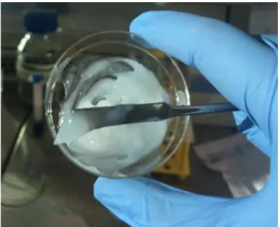
All bioink compositions were prepared (see Table II.1 and Table II.2) as follows (Fig. II.1); the alginate solution (3%) was prepared by injecting 8mL of previously prepared mannitol solution (4.6%), to a sterile bottle containing 0,250g of freeze-dried alginate. CorgelTM
tyramine substituted sodium hyaluronate (TS-NaHy) was used as the hyaluronic acid hydrogel. Enzymatic CNF dry content was 2.4%, being both enzymatic CNF and RGD-modified CNF mixed with mannitol 4.6%.
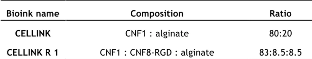
For the pilot experiment, CELLINK R 1 was prepared by mixing, for 2min, enzymatic CNF, RGD-modified CNF and alginate, until obtaining homogeneous hydrogel, starting with the ratio described in Table II.1. This composition was the first studied, which served as base to develop the final bioinks.
To prepare the final bioinks, the amount of all CNF dispersions, alginate and hyaluronic acid solutions taken depended on the desired amount of bioink to be prepared, always in regard of the corresponding ratio. The same process was used as in the pilot experiment.
Table II.1 — Bionk compositions for pilot experiment.
Bioink name Composition Ratio
CELLINK CNF1 : alginate 80:20
CELLINK R 1 CNF1 : CNF8-RGD : alginate 83:8.5:8.5
Table II.2 — Bionk compositions for full study.
Bioink name Composition Ratio
CELLINK H CNF1 : hyaluronic acid 70:30
CELLINK SH CNF8 : hyaluronic acid 70:30
CELLINK RC CNF1 : CNF8-RGD : hyaluronic acid 70:10:20
CELLINK RCH CNF1 : CNF8-RGD : alginate 70:10:20
CNF1 – enzymatic CNF; CNF8 – carboxylated CNF; CNF8-RGD – RGD-modified CNF
Figure II.1 – Mixing process of the bioink formulation.
2.4 – Rheology and printability studies
Rheology tests were performed for all bioink compositions (Table II.1 and Table II.2) for greater insight on the bioink behaviour, aiming to study their shear-thinning properties and viscosity. Discovery Hybrid Rheometer (DHR) from TA Instruments was used to perform the tests.
Printability tests were performed using two different bioprinters: 3D Discovery from RegenHU, Switzerland and Inkredible from CELLINK, Sweden.
Printing parameters:
- Printers: 3D Discovery from RegenHu, Switzerland and Inkredible from Cellink, Sweden
- 3D Discovery: printer head PH1, 300µm microvalve
- Grid measurements: 5x6 mm grids, 4 layers - Material for printing: see Table II.1 and Table II.2
- Pressure used: from 20 to 40 kPa, for pilot experiment; from 20 to 25 kPa, for full study
2.5 – Cell Source, expansion and harvesting
The cell source used was human dermal fibroblasts (mean age 40 years, female, abdominal skin) bought from ATCC Primary Cell Solutions. The cells were cultured in 150 cm2
flasks (TPP), in Dulbecco’s Modified Eagle Medium (DMEM, Gibco) with high glucose, phenol red and glutamax, supplemented with 10% (v/v) FBS (Gibco), 100 U/mL penicillin G and 100 µg/mL streptomycin (Gibco). The cells were maintained at 37°C in a humidified 5% CO2
incubator, changing medium every 2 days and used at passages 6-9.
For the bioprinting experiments, cells were harvested at 90-100% confluence with PBS (Gibco) and then incubated at 37°C with TrypLE Express (Gibco) for 7-10 min. Afterwards, cells were counted and centrifuged at 200 G for 5 min, and cell pellet re-suspended in growth medium, resulting in cell concentrations of 5.5 M cells/100µL of medium.
2.6 – Overview of cell studies
The cell studies performed in this project and its conditions are shown in Table II.3. The experiment was carried out through 23 days, since one of the objectives was to analyse fibroblast viability, attachment and proliferation. After crosslinking, the printed constructs were cultured in growth medium. Within the same ink composition (CELLINK RC and RCH), at day 3 after printing, half of the samples were cultured with differentiation medium DMEM without glutamine and phenol red, supplemented with 2% (v/v) FBS (Gibco), 1% Glutamax, 100 U/mL penicillin G and 100 µg/mL streptomycin (Gibco), and 5ng/mL of TGF-β, and the other half without, evaluating the effect of this known fibroblast proliferation promoter.
2.6.1 – Cell viability
One of the key factors to be analysed in this project is to demonstrate if the cells are able to survive the printing process, thus cell viability studies are essential. This was done using Live/Dead Cell Imaging Kit (488/570) (Life Technologies). Briefly, the samples were collected from the well plate and put in another one with HBSS for 30 min at 37°C. Meanwhile, the staining solution was prepared: the green vial (1mL) was transferred to the red vial (1µL) and mixed thoroughly. After this, 1mL of DMEM was added to the mixture and 250µL were dispensed in every well, throughout 40 min at 37°C. After this, the well plate was covered with aluminium foil and worked in the dark as much as possible, to avoid photo
bleaching. The last step was the washing of the samples, twice, with DMEM. The cells were further visualized with a fluorescence microscope (IX73, Olympus) and Texas Red and FTIC filters were used.
2.6.2 – Cell morphology
Cell morphology is also a key factor to be analysed, to evaluate the occurrence, or not, of cell adhesion to the ink. This was done by performing a different staining technique, staining the cell’s actin and nuclei. Briefly, the samples were collected from the well plate and put in another one with HBSS for 30 min at 37°C. After that, the samples were fixated with 4% formaldehyde for 1 hour at room temperature. Samples were washed again and Triton X100 in HBSS was used to permeabilize the cells for 30 min at 37°C. Meanwhile, the staining solution was prepared, adding 2 drops of ActinGreen per mL of solution needed and a 2000x dilution of DAPI. Samples were stained and incubated for 30 min. Then, the samples were washed with HBSS a few times and kept on a crosslinking agent solution (CaCl2 or H2O2). The
morphology of the cells was visualized with a confocal laser-scanning microscope (LSM 710 NLO, Carl Zeiss).
2.6.3 – Collagen production
Collagen production by human dermal fibroblasts was analysed by performing AlcianBlue Van Gieson staining. The samples for the conjugated bioinks for day 23 were embedded in paraffin and sectioned, following protocol. After that the staining took place. Histocenter, Gothenburg, Sweden, performed the described process and further analysis performed using a light microscope (IX73, Olympus).
Table II.3 — Overview of cell studies experiments.
CNF1 – enzymatic CNF; CNF8 – carboxylated CNF; CNF8-RGD – RGD-modified CNF
Ink name Composition Group Ratio
Method Total culture time Live/Dead Assay time points Confocal microscopy time points Histology time points CELLINK H
CNF1 : hyaluronic acid - 70:30 Day 1, 7, 14 Day 14 - 14 days
CELLINK SH
CNF8 : hyaluronic acid - 70:30 Day 1, 7, 14 - - 14 days
CELLINK RC CNF1 : CNF8-RGD : hyaluronic acid
with TGF-β
70:10:20
Day 1, 7 Day 7, 14, 23 Day 23 23 days
without TGF-β Day 1, 7 Day 3, 7, 14, 23 Day 23 23 days
CELLINK RCH CNF1 : CNF8-RGD : alginate
with TGF-β
70:10:20
Day 1, 7 Day 7, 14, 23 Day 23 23 days
Chapter III
Results and Discussion
3.1 - Characterization of inks
3.1.1 – XPS analysis
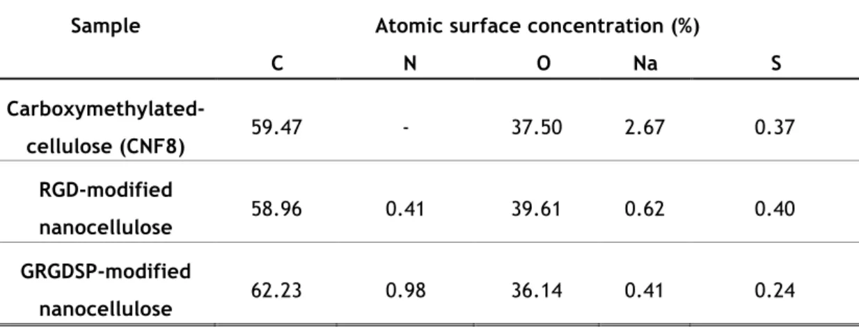
The chemical composition of the RGD and GRGDSP-modified nanocellulose was monitored and evaluated by performing XPS and comparing the results with the non-modified nanocellulose. Table III.1 shows the results. The increase of nitrogen 1s is evident with the coupling of the peptide sequences on the nanocellulose fibers, due to the presence of amine groups. A considerable difference on the concentration of sodium 1s is also noted between the modified and the non-modified nanocellulose. The bioconjugation process involves a purification step – dialysis – that means the sodium is being removed from the dispersion.
Table III.1 — Atomic surface concentrations of modified and non-modified nanocelluloses
determined by XPS.
Sample Atomic surface concentration (%)
C N O Na S Carboxymethylated-cellulose (CNF8) 59.47 - 37.50 2.67 0.37 RGD-modified nanocellulose 58.96 0.41 39.61 0.62 0.40 GRGDSP-modified nanocellulose 62.23 0.98 36.14 0.41 0.24
3.1.2 – DLS dispersion analysis
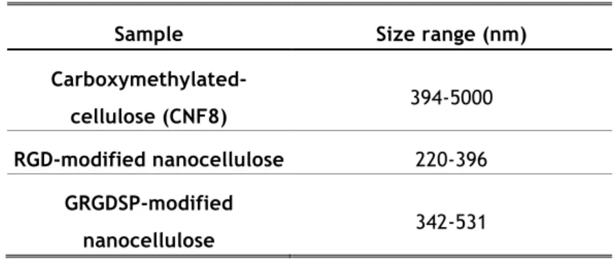
The colloidal properties and the stability of the nanocellulose dispersions were evaluated by performing DLS. The size range and zeta potential were measured. Table III.2 shows the size range of the different nanocelluloses, suggesting the aggregation of the fibers on the carboxymethylated nanocellulose. When comparing both conjugated CNF, the GRGDSP-modified nanocellulose shows a bigger particle size, mainly due to its higher charge density and peptide sequence size. Table III.3 shows a greater zeta potential value for the conjugated CNF, which is related with their charge density, increased during the bioconjugation process.
The correlation graph (Fig. III.1) also gives us insight on the aggregation of the nanocellulose fibrils. The Brownian motion (random movements of colloidal particles) of conjugated CNF particles is much faster than the non-modified CNF, due to the greater charge density after the bioconjugation process. These charged particles experience repulsion forces, so their correlation delay time is lower. Comparing to the carboxymethylated cellulose is clear to say that these fibers are aggregated.
Table III.2 — Particle size measurement determined by DLS.
Table III.3 — Zeta potential measurement determined by DLS.
Sample Size range (nm)
Carboxymethylated-cellulose (CNF8) 394-5000
RGD-modified nanocellulose 220-396
GRGDSP-modified
nanocellulose 342-531
Sample Zeta potential (mV)
Carboxymethylated-cellulose (CNF8) -37.5
RGD-modified nanocellulose -41.5
GRGDSP-modified
Figure III.1 – Correlation graph determined by DLS of pure carboxymethylated CNF (black),
RGD-modified CNF (red) and GRGDSP-RGD-modified CNF (blue).
3.1.3 – FTIR spectra analysis
Figure III.2 shows the FTIR spectra of pure CNF, enzymatic and carboxymethylated, and of RGD-modified CNF. The broad spectrum bands between 3000 and 3600 cm-1 detected in all
types of CNF are assigned to the stretching vibrations of –OH and –CH groups of the cellulose basic structure. The band ranging from 1500 to 1700 is the most significant and contains the signals from the carboxylic groups vibrations. The greatest difference between the spectra was observed at 1600 cm-1, between the carboxymethylated nanocellulose and the
RGD-modified nanocellulose, which corresponds to the asymmetric stretching vibrations of the amide bond, between the carboxyl and amine groups, formed when conjugating RGD on the nanocellulose.
3.2 – Rheology Studies
Rheology tests were performed (Fig. III.3) with the goal of measuring the inks shear-thinning properties and viscosity. Shear shear-thinning is a non-Newtonian behaviour of some hydrogel, referring to the inverse relationship between shear rate and viscosity, i.e. fluid viscosity decreases while increasing the shear rate. Thus, when applying shear rate the
Figure III.2 – FTIR spectra of pure enzymatic CNF (black), carboxymethylated CNF (red) and
RGD-modified CNF (blue).
polymer fibers orient within the dispersion and the sample gets less viscous. The shear thinning properties provides the bioink with a high printing fidelity, meaning that the structures printed will have a high resolution [7]. This analysis of the material’s behaviour can be accomplished using a rheometer. The results show an approximately shear thinning behaviour for every ink composition and similar to CELLINK, which has well studied and defined mechanical properties.
3.3 – Printability Studies
Printability tests were performed for the different bioink compositions. After mixing all the components with the correct ratio, the bioinks were printed using Inkredible (Cellink), an extrusion 3D bioprinter, and 3D Discovery (RegenHu), an inkjet 3D bioprinter. Both printers were used to evaluate their printing resolution, fidelity and reproducibility. For the full study bioinks only 3D Discovery was used. All the bioinks were mixed with DMEM in a proportion of 1:0.1, with the goal of mimicking the conditions for when bioprinting with the cell suspension.
The S-test, although very simple, offer information about the printability, printing fidelity and reproducibility. For when bioprinting with Inkredible, a different structure was adopted,
4000
3500
3000
2500
2000
1500
1000
500
0.05
0.10
0.15
0.20
0.25
0.30
1700 1650 1600 1550 1500 0.03 0.04 0.05 0.06 0.07 0.08 0.09 Absor ba nce Wavelength (cm-1)Absor
ba
nce
Wavelength (cm
-1)
CNF-Enzymatic
CNF-Carboxymethylated
CNF-RGD
Wavenumber (cm
-1)
Wavenumber (cm-but with the same goal (Fig. III.4). Briefly, the letter S is printed on a glass slide and the material dispensed by the printer is weighted. Different parameters, such as the pressure and needle size, are compared, classifying this test as a very useful initial printability study (Fig. III.5).
Figure III.3 – Viscosity versus shear rate curve for the bioinks developed, comparing with CELLINK.