Abstract— Developing an adequate network architecture for supporting data communications in vehicular networks is critical to overcome the challenges caused by highly dynamic network topology, connectivity disruption, and intermittent connectivity issues. Among several approaches available in the literature proposed to address these problems, vehicular delay-tolerant networking (VDTN) architecture appears as a recent and innovative solution that integrates the concepts of end-to-end, asynchronous, and variable-length bundle oriented communication; Internet protocol over VDTN; and out-of-band signaling. VDTN architecture, protocols and services are in a fairly early stage of development. Therefore, simulation appears as an important tool providing a highly flexible, low-cost, and fast answer for research questions, and furnishes important inputs for exploring through prototyping. This paper presents and describes the proposal and construction of a simulation tool for VDTN networks, called VDTNsim.
Index Terms— Vehicular delay tolerant networks (VDTN); Network simulation; Simulation tools; Performance assessment.
I. INTRODUCTION
In recent years, vehicular networking has attracted significant interests from both academia and industry because of its potential for enabling a plethora of novel applications and services. Some possible applications include networks to disseminate information advertisements or safety related information, networks to distribute multimedia content, and monitoring networks for data collection. Vehicular networks can also be considered as a mean to provide connectivity to remote rural communities and regions, or to assist communication between the rescue teams and other emergency services in catastrophe hit areas lacking a conventional communication infrastructure. Nevertheless, vehicular networks raise many challenges. Most of the problems in achieving data communication in these networks arise from the high mobility of vehicles, which is responsible for a highly dynamic network topology and to short contact durations [1]. Limited transmission ranges, physical obstacles, and interferences also lead to disruption and intermittent connectivity [2]. In addition, the large distances usually involved and low node densities contribute to network partition. Therefore, a contemporaneous end-to-end path from source to destination may not exist.
Several approaches have been proposed in the literature to address the problem of providing data communication on
vehicular networks. Vehicle ad hoc network (VANET) [3] is a type of ad hoc network that was presented as an important component of intelligent transportation systems (ITS) [4]. In VANETs, conventional protocols for routing assume end-to-end connectivity. Thus, they were not designed to handle conditions caused by network disconnection, partitions, or long delays [5, 6]. Researchers tried to overcome these limitations by incorporating the store-carry-and-forward paradigm proposed for delay tolerant networks (DTNs) [7]. The concept of “DTN enabled VANETs” was introduced, for example, in [8, 9].
Recently, a new layered architecture for vehicular communications, called vehicular delay-tolerant network (VDTN), was proposed [10]. VDTN network architecture is also inspired by the store-carry-and-forward concept. However, it is fundamentally different from the previous approaches because it operates as an overlay network over the link layer (OSI Model), and separates the control plane and data plane employing out-of-band signaling. VDTN uses large size data packets, called bundles.
Deploying and operating a real testbed to evaluate the behavior of protocols and the network performance under a large-scale VDTN supposes a great effort. Moreover, testbeds have a limited flexibility and their use is limited to those who have access to it. Simulation tools may support detailed modeling of VDTNs and performance studies under various conditions. Simulation results are easier to analyze than experimental results because they are easily repeatable. Simulation is also economical because it is possible to carry out experiments without the real network hardware. Therefore, simulation appears as an essential tool to investigate the behavior and performance of new protocols and applications for VDTNs.
To the best of our knowledge, a simulator for VDTN networks is not available in the related literature yet. For this reason, the aim of this paper is the proposal of a simulation framework that models the behavior of the VDTN architecture, presenting its design and construction. This simulation framework is named VDTNsim.
The remainder of this paper is organized as follows. Section II overviews the principal concepts of the VDTN architecture. Section III describes VDTNsim, while Section IV focuses on its demonstration. Finally, Section V summarizes the main conclusions of this work and points some future work.
VDTNsim: A Simulation Tool for
Vehicular Delay-Tolerant Networks
Vasco N. G. J. Soares
1,2,3, Farid Farahmand
4, and Joel J. P. C. Rodrigues
1,21Instituto de Telecomunicações, Portugal
2Department of Informatics, University of Beira Interior, Covilhã, Portugal 3Superior School of Technology, Polytechnic Institute of Castelo Branco, Portugal
4Department of Engineering Science, Sonoma State University, CA, USA
II. VDTNARCHITECTURE
Vehicular delay-tolerant networking [10] introduces a new network architecture which aims to solve problems faced by data communication in sparse and disconnected vehicular network scenarios. VDTN follows the principle of store-carry-and-forward routing proposed for DTNs, in order to cope the problems caused by intermittency, disconnection and long delays. This paradigm can be described as follows. A network node stores a bundle, using some form of persistent storage, while waiting for a connection opportunity. When a communication opportunity arises, the bundle is forwarded to an intermediate node, according to a hop-by-hop routing scheme. This process is repeated and the bundle is relayed hop-by-hop until eventually reaching its destination. However, in contrary to DTN architecture proposal, which introduces an overlay bundle layer between the transport and application layer to allow the interconnection of highly heterogeneous networks [11], VDTN architecture places the bundle layer over the data link layer introducing an IP over VDTN approach (Figure 1). The protocol data unit at the VDTN bundle layer is the above-mentioned bundle, which aggregates several IP packets with common characteristics, such as the same destination node or generated with data from the same application.
Fig. 1. DTN and VDTN layered architectures.
Another distinctive feature of VDTN architecture when compared with DTN is the clear separation between control and data planes. The VDTN bundle layer is divided into two layers: the bundle signaling control layer (BSC) and the bundle aggregation and de-aggregation layer (BAD). BSC layer executes the control plane functions, such as signaling messages exchange, node localization, resources reservation (at the data plane) and routing, among others. The signaling messages include information such as, but not limited to, node type, geographical location, route, velocity, data plane link range, power status, storage status, bundle format and size, delivery options, and security requirements, among others. BAD executes the data plane functions that deal with data bundles. These functions include, among others, buffer management (queuing) and scheduling, traffic classification, data aggregation/de-aggregation, and forwarding.
VDTN uses out-of-band signaling, meaning that the control plane exchanges the signaling information through a separate,
dedicated, low-power, low bandwidth, and long-range link. This link is always active to allow node discovery. On the contrary, the data plane uses a high-power, high bandwidth, and short-range link to exchange data bundles. The data plane link connection is active only during the estimated contact duration time and if there are data bundles to be exchanged between the network nodes. Otherwise, it is not activated. This approach is described in [10, 12], and it is considered very important because it not only ensures the optimization of the available data plane resources (e.g., storage and bandwidth) [12], but also allows to save power, which is very important for energy-constrained network nodes [10, 13].
The VDTN approach to control plane and data planes separation allows both planes to evolve independently. This is very important since new specifications, functions and services can be deployed at one of them without needing to change the other one.
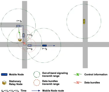
Figure 2 illustrates the interactions between two types of network nodes in a VDTN (mobile and stationary relay nodes). Mobile nodes (e.g., vehicles) collect and disseminate data bundles opportunistically. Stationary relay nodes are fixed devices with store-and-forward capabilities that are located at road intersections. Mobile nodes use relay nodes to deposit and pickup data. Relay nodes increase contact opportunities in scenarios with low node density. Thus, they contribute to increase the data bundles delivery ratio and to decrease their delivery delay, as discussed in [14].
The principle of out-of-band signaling is also illustrated in this figure. At the time t+t0, two network nodes detect each other and start exchanging signaling messages through the control plane link connection. Based on this information, the data plane connection is configured and activated on both nodes at the time t+t1. Then, the data bundles are forwarded until the time t+t2. The data plane connection is deactivated after this instant since the nodes are no longer in the data plane link range of each other.
Fig. 2. Control information and data bundles exchange between network nodes in a VDTN.
III. VDTNNETWORK SIMULATION TOOL
To date, no simulator has been specifically developed for VDTN architecture, not even through extensions of existing simulation tools. To overcome this limitation, instead of developing a new simulator from scratch, we opted to modify and augment the source code of a well-known simulator in the topic of delay-tolerant networking.
VDTNsim is built up on core of the Opportunistic Network Environment simulator (ONE), version 1.3.0 [15, 16]. ONE was developed in the SINDTN and CATDTN projects supported by Nokia Research Center (Finland) and in the TEKES ICT-SHOK Future Internet project. It is an agent-based discrete event simulator that has been used in many DTN research, and is constantly updated with new features. Briefly, this simulator is capable of i) generating node movement using different internal and external movement models; ii) supporting different node types; iii) supporting different DTN routing schemes; iv) displaying in real time information related to message transfer and node movement in a graphical user interface; v) producing reports about node movement, message passing, and general statistics. Complete details regarding this simulator are provided in [15], and its Java source code is freely available for download at [16].
Authors decided to change and extend this DTN simulator instead of a VANET simulator because ONE implements the store-carry-and-forward paradigm also used in the VDTN architecture. ONE also offers support for several synthetic vehicular mobility models. Furthermore, it allows the creation of simulation scenarios with groups of nodes with different characteristics (e.g., mobile, fixed), and capabilities (e.g., storage space, radio interface), such as the one illustrated in Figure 2.
As expected, several extensions were developed for ONE in order to modify and augment this DTN simulation environment to model the behavior of the VDTN architectural solutions for vehicular communications. Figure 3 presents a unified modeling language (UML) deployment diagram that illustrates how the developed components work together to model the VDTN architecture in ONE simulator.
Fig. 3. UML deployment diagram representing the implementation perspective of the VDTNsim framework in ONE simulator.
More specifically, it was necessary to modify the simulator code to model the store-carry-and-forward overlay network above the link layer. Furthermore, new code was written to implement the features of control and data planes separation using out-of-band signaling. This required the implementation of the control plane functions provided by the bundle signaling control layer (e.g., signaling, node localization, resources reservation, routing), and the data plane functions provided by the bundle aggregation and de-aggregation layer (e.g., buffer management, scheduling, traffic classification, aggregation/de-aggregation, forwarding).
Out-of-band signaling was achieved by the creation of a feature that allows network nodes to have two network interfaces, each with different network characteristics (e.g., transmission range, data transfer rate). As described in the previous section, the control plane uses one of these network interfaces whereas the data plane uses the other one.
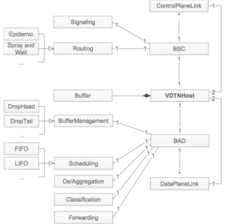
Figure 4 shows an UML class diagram that outlines the most important classes and their relationships, which were implemented in the VDTNsim framework. Though many details are omitted due to the space limitation, this comprehensive diagram provides an overview of the virtualization of the VDTN network model.
Fig. 4. UML class diagram describing the general classes of the VDTN architecture model and their relations to each other.
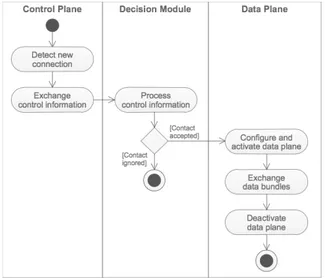
Further details about the interaction between the control plane and the data plane are provided in Figure 5. This figure depicts a UML activity diagram that describes the overall flow of control from activity to activity executed at each of these planes. New contact opportunities are detected at the control plane connection. Then, control information is exchanged. A high-level decision module is responsible for the analysis of the control information to decide whether to ignore or accept the contact. If the decision module accepts the contact opportunity, then, the control information is used for data plane setup, activation, control, and deactivation, in order to optimize the data bundle transmission, performed at the data plane.
Fig. 5. UML activity diagram describing the control and data planes interaction coordinated by the decision module.
Regarding the implementation of VDTNsim framework, one of our major concerns was the programming of all components in a complete modular way, in order to be flexible, easily modified, and extensible. Another concern was the preservation of the simple plain-text simulation configuration files used by ONE. These files were extended to include support to the new parameters introduced by the protocols and services related with the VDTN architecture.
IV. DEMONSTRATION OF VDTNSIM
This section considers a case study for illustrating the use of the VDTNsim simulation tool and the benefits introduced by the VDTN network architecture.
A. Simulation Scenario
The simulation scenario is based on a map-based model of a part of Helsinki (Finland) presented in Figure 6. During a 12 hours period of time (e.g., from 8:00 to 20:00), 100 mobile nodes (e.g., vehicles) move on the map roads between random locations. Their average velocity changes between 20, 30, 40, and 50 km/h, across the simulations, and they have random pause times between 5 and 15 minutes. Each of the mobile nodes has a 50 Megabytes buffer.
Five stationary relay nodes are placed at the road intersections presented in Figure 6, in order to increase the number of contact opportunities. Each of the stationary relay nodes has a 500 Megabytes buffer.
Data bundles with sizes uniformly distributed in the ranges of [25KB, 100KB], [250KB, 500KB], and [750KB, 1MB] (Bytes), are sent from a random source to a random destination mobile node, at intervals uniformly distributed in the range [25, 35] seconds. These bundles represent aggregates of traffic generated by different VDTN applications, and have a time-to-live (TTL) of 60 minutes. TTL is a timeout value that expresses when bundles should be discarded from nodes’ buffers, since they are no longer meaningful.
Network nodes exchange signaling information
out-of-band, using a link connection with an omni-directional transmission range of 90 meters. Data bundles are transmitted using a link with a data rate of 4.5 Mbps and an omni-directional transmission range of 30 meters, as proposed in [17]. Binary spray and wait [18] is used as the underlying bundle routing scheme.
Fig. 6. Simulation scenario with locations of the stationary relay nodes. B. Performance Analysis
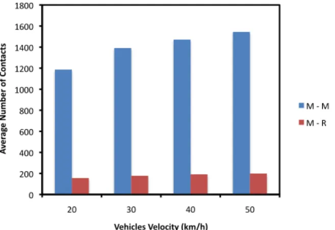
The results observed in the simulation experiments demonstrate the importance of the approach introduced by the VDTN architecture to sparse vehicular networks. Figure 7 shows that the majority of contacts registered in the network occurred between mobile nodes. Only few contacts between mobile nodes and relay nodes were observed. Since relay nodes are power-limited because they run on solar panels or batteries, it is essential to optimize their energy consumption. By introducing control and data planes separation (using out-of-band signaling), VDTN architecture enables these nodes to spend little energy while searching for contact opportunities. Moreover, their high-power, high bandwidth, and short-range link that is used to transmit and receive data bundles, is active during the small amount of time that last contacts. This allows extending battery life of these nodes, which have an essential role in increasing the overall performance of the network in terms of delivery ratio and delivery probability [14].
At each contact opportunity, if network nodes are not able to predict the contact duration, they may start to transfer data bundles whose size exceeds the maximum number of bytes that can be transmitted before the link is finished. This results in incomplete bundle transmissions. If fragmentation is not allowed, the partially transferred bundles are discarded, causing the waste of data plane link capacity and of energy resources. As proposed in [12], VDTN out-of-band signaling can be used to implement a node localization function that allows network nodes to estimate contact durations. This function improves the data plane link utilization, increasing the number of successful bundle transmissions. Thus, network nodes store, carry, and forward more data bundles. As may be observed in Figure 8, this increases bundles probability to be successfully delivered to their final destination.
!" #!!" $!!" %!!" &!!" '!!!" '#!!" '$!!" '%!!" '&!!" #!" (!" $!" )!" !" #$% &' $!() *+ $%!, -!., /0 &102! 3$4516$2!3$6,1507!89*:4;! *"+"*" *"+","
Fig. 7. Average number of contacts registered between mobile nodes (M – M), and mobile nodes and relay nodes (M – R), as a function of vehicles speed.
!" !#$" !#%" !#&" !#'" !#(" !#)" !#*" !#+" !#," $" %!" &!" '!" (!" !"# $% "& '()& *+ ,+ $#$ -' ( ."/$0#"1(."#*0$-'(2345/6( -./012.0/" 34"-./012.0/"
Fig. 8. Bundle delivery probability as a function of vehicles speed.
V. CONCLUSIONS AND FUTURE WORK
This paper presented a simulation framework, named VDTNsim, which models the VDTN network architecture, a new proposal with a layered architecture for vehicular communications. The purpose of VDTNsim is to support research studies related with the development, experimentation, and performance evaluation of new protocols and services for VDTNs. Since VDTNsim is built up on the core of the ONE simulator, we provide the ONE simulator community with a valuable tool for VDTN simulation, contributing to a wider adoption of this simulator.
Developing a new module to support an energy-efficient geographic routing protocol for the VDTNsim simulation tool is one of our interests for future work.
ACKNOWLEDGMENTS
Part of this work has been supported by Instituto de Telecomunicações, Next Generation Networks and Applications Group (NetGNA), Portugal, in the framework of the Project VDTN@Lab, and by the Euro-NF Network of Excellence of the Seventh Framework Programme of EU, in the framework of the Specific Joint Research Project VDTN.
REFERENCES
[1] J. Burgess, B. Gallagher, D. Jensen, and B. Levine, "MaxProp: Routing for Vehicle-Based Disruption-Tolerant Networks", in INFOCOM 2006 -
The 25th IEEE International Conference on Computer Communications,
Barcelona, Catalunya, Spain, 2006, pp. 1-11.
[2] J. Morillo-Pozo, J. M. Barcelo-Ordinas, O. Trullos-Cruces, and J. Garcia-Vidal, "Applying Cooperation for Delay Tolerant Vehicular Networks", in Fourth EuroFGI Workshop on Wireless and Mobility, Barcelona, Spain, 2008.
[3] S. Yousefi, M. S. Mousavi, and M. Fathy, "Vehicular Ad Hoc Networks (VANETs): Challenges and Perspectives", in 6th International
Conference on ITS Telecommunications (ITST 2006), 2006, pp. 761-766.
[4] J. Anda, J. LeBrun, D. Ghosal, C.-N. Chuah, and M. Zhang, "VGrid: Vehicular AdHoc Networking and Computing Grid for Intelligent Traffic Control", in IEEE 61st Semiannual Vehicular Technology
Conference (VTC 2005), Stockholm, Sweden, 2005, pp. 2905-2909.
[5] M. Abuelela and S. Olariu, "Traffic-Adaptive Packet Relaying in VANET", in The Fourth ACM International Workshop on Vehicular Ad
Hoc Networks (VANET 2007), in conjunction with ACM MobiCom 2007, Montréal, QC, Canada, 2007, pp. 77-78.
[6] F. Li and Y. Wang, "Routing in Vehicular Ad Hoc Networks: A Survey", IEEE Vehicular Technology Magazine, vol. 2, pp. 12-22, June 2007.
[7] V. Cerf, S. Burleigh, A. Hooke, L. Torgerson, R. Durst, K. Scott, K. Fall, and H. Weiss, "Delay-Tolerant Networking Architecture", RFC 4838, April 2007, ftp://ftp.rfc-editor.org/in-notes/rfc4838.txt
[8] P.-C. Cheng, K. C. Lee, M. Gerla, and J. Härri, "GeoDTN+Nav: Geographic DTN Routing with Navigator Prediction for Urban Vehicular Environments", Mobile Networks and Applications, Springer, vol. 15, pp. 61-82, February 2010.
[9] L. Franck and F. Gil-Castineira, "Using Delay Tolerant Networks for Car2Car Communications", in IEEE International Symposium on
Industrial Electronics 2007 (ISIE 2007), Vigo, Spain, 2007, pp.
2573-2578.
[10] V. N. G. J. Soares, F. Farahmand, and J. J. P. C. Rodrigues, "A Layered Architecture for Vehicular Delay-Tolerant Networks", in The Fourteenth
IEEE Symposium on Computers and Communications (ISCC’09),
Sousse, Tunisia, 2009, pp. 122-127.
[11] K. Scott and S. Burleigh, "Bundle Protocol Specification", RFC 5050, November 2007, http://www.rfc-editor.org/rfc/rfc5050.txt
[12] V. N. G. J. Soares, J. J. P. C. Rodrigues, F. Farahmand, and M. Denko, "Exploiting Node Localization for Performance Improvement of Vehicular Delay-Tolerant Networks", in 2010 IEEE International
Conference on Communications (IEEE ICC 2010) - General Symposium on Selected Areas in Communications (ICC'10 SAS), Cape Town, South
Africa, 2010.
[13] N. Banerjee, M. D. Corner, and B. N. Levine, "An Energy-Efficient Architecture for DTN Throwboxes", in 26th IEEE International
Conference on Computer Communications (INFOCOM 2007),
Anchorage, Alaska, USA, 2007, pp. 776-784.
[14] J. J. P. C. Rodrigues, V. N. G. J. Soares, and F. Farahmand, "Stationary Relay Nodes Deployment on Vehicular Opportunistic Networks", in
Mobile Opportunistic Networks: Architectures, Protocols and Applications, M. K. Denko, Ed. USA, Auerbach Publications, CRC
Press, 2010.
[15] A. Keränen, J. Ott, and T. Kärkkäinen, "The ONE Simulator for DTN Protocol Evaluation", in Second International Conference on Simulation
Tools and Techniques (SIMUTools 2009), Rome, 2009.
[16] Helsinki University of Technology - TKK Comnet, "The Opportunistic Network Environment (ONE) simulator", http://www.netlab.tkk.fi/tutkimus/dtn/theone/, accessed at May, 2010. [17] A. Keränen and J. Ott, "Increasing Reality for DTN Protocol
Simulations", Helsinki University of Technology, Networking Laboratory, Technical Report, July, 2007.
[18] T. Spyropoulos, K. Psounis, and C. S. Raghavendra, "Spray and Wait: An Efficient Routing Scheme for Intermittently Connected Mobile Networks", in ACM SIGCOMM 2005 - Workshop on Delay Tolerant
Networking and Related Networks (WDTN-05), Philadelphia, PA, USA,


