Universidade Nova de Lisboa Faculdade de Ciˆencias e Tecnologia Departamento de Inform´atica
Dissertac¸˜ao de Mestrado
Mestrado em Engenharia Inform´atica
Unified Cooperative
Location System
David Precatado Navalho (25987)
Universidade Nova de Lisboa Faculdade de Ciˆencias e Tecnologia Departamento de Inform´atica
Dissertac¸˜ao de Mestrado
Unified Cooperative
Location System
David Precatado Navalho (25987)
Orientador: Prof. Doutor Nuno Manuel Ribeiro Preguic¸a
Disserta¸c˜ao apresentada na Faculdade de Ciˆencias e Tecnologia da Universidade Nova de Lisboa para a obten¸c˜ao do Grau de Mestre em Engenharia Inform´atica.
Acknowledgements
Em primeiro lugar gostaria de agradecer ao Departamento de Inform´atica (DI) da FCT-UNL, pela bolsa de investigac¸˜ao concedida.
Em particular, gostava de agradecer ao meu orientador, Nuno Manuel Preguic¸a, n˜ao s ´o pela orientac¸˜ao, pelo apoio e pela disponibilidade, mas tamb´em pela enorme dedicac¸˜ao e pelas oportunidades proporcionadas ao longo da realizac¸˜ao deste trabalho. Queria tamb´em agradecer aos meus colegas e amigos de trabalho do DI, em espe-cial ao Bruno F´elix, H´elio Dolores, Jo˜ao Soares, Maria Caf´e, Nuno Luis, Pedro Sousa e Sim˜ao Mata pela disponibilidade, apoio, ideiais, discuss ˜oes, coment´arios, boa disposic¸˜ao e longas noitadas.
Ao professor Jo˜ao Lourenc¸o, por todos os conselhos, discuss ˜oes e partilhas.
Aos meus familiares, pela paciˆencia, compreens˜ao e incentivo que me deram du-rante todo o percurso acad´emico.
Quero tamb´em deixar o meu agradecimento `a Catarina, n˜ao s ´o pelo incentivo, paciˆencia e enorme compreens˜ao demonstrados, mas acima de tudo por fazer parte da minha vida.
Summary
The widespread use of smaller, less expensive, and more capable mobile devices, has opened the door for more complex and varied mobile computing applications. Additionally, manufacturers are increasingly equipping these handheld devices with every type of wireless connectivity and sensors that can be explored for providing more complex services.
In recent years, several techniques for location estimation have been developed, providing different degrees of accuracy. Some of these solutions require the installation of specific hardware in the environment, while others explore the existing infrastruc-ture. In particular, it is possible to explore the existing communication infrastructure to build a location system relying on signal strength measures.
However, while several systems already exist to locate users based on different approaches, there is no single one that is good for every situation while providing high accuracy, low cost and ubiquitous coverage. Not only that, but very few research has been made regarding on how a group of users can cooperate to improve accuracy or reduce energy consumption while using the location system.
This work presents the Unified Cooperative Location System, a modular and ex-tensible location system. Its modular design can use every available technology on each device and different algorithms for location estimation. This approach allows to provide location services with high availability by relying on different technologies. It also allows to reduce the energy consumption on devices by sharing the responsibility of executing energy-heavy operations.
Sum´ario
O aumento do uso de dispositivos cada vez mais pequenos, mais baratos e com maiores capacidades, abriu a porta para variadas aplicac¸ ˜oes mais complexas. Al´em disso, os fabricantes est˜ao constantemente a equipar estes dispositivos port´ateis com todos os tipos de conectividade sem fios e sensores.
Tirando partido das novas caracter´ısticas destes dispositivos, um grande n ´umero de t´ecnicas e sistemas foram propostos para fornecer localizac¸˜ao. Algumas destas soluc¸ ˜oes requerem a instalac¸˜ao de hardware espec´ıfico nas proximidades, enquanto outras exploram a infra-estrutura existente de comunicac¸ ˜oes sem fios. Em particular, ´e poss´ıvel explorar a infra-estrutura para construir um sistema de localizac¸˜ao baseado em medidas de forc¸a de sinal.
No entanto, apesar de existirem v´arios sistemas para localizar pessoas, partilhar locais, ou mesmo fornecer servic¸os, n˜ao existe um ´unico que seja bom para todas as situac¸ ˜oes, fornecendo boa precis˜ao, baixo custo e cobertura ub´ıqua. Al´em disso, muito pouca pesquisa tem sido feita sobre como um grupo de utilizadores pode cooperar para melhorar a precis˜ao ou reduzir o consumo de energia enquanto usam um sistema de localizac¸˜ao.
Este trabalho apresenta o Unified Cooperative Location System, um sistema modu-lar e extensivel. O seu desenho modumodu-lar permite usar todas as tecnologias disponiveis para cada dispositivo, e usar diferentes algoritmos para estimar a localizac¸˜ao. Esta abordagem permite disponibilizar servic¸os de localizac¸˜ao com alta disponibilidade, ao usar diferentes tecnologias. Tamb´em permite reduzir o consumo de energia em dispos-itivos, ao partilhar a responsabilidade de usar operac¸ ˜oes com altos gastos de energia.
Contents
List of Figures xvi
List of Tables xvii
1 Introduction 1
1.1 Context . . . 1
1.2 Motivation . . . 2
1.3 Implemented Solution . . . 3
1.4 Main Contributions . . . 4
1.5 Organization . . . 5
2 Related Work 7 2.1 Basic Techniques . . . 7
2.1.1 Performance of Location Systems . . . 7
2.1.2 Location Algorithms . . . 8
2.1.3 Signal Strength Modeling . . . 11
2.1.4 MinMean and MinMode Algorithms . . . 12
2.1.5 Wardriving . . . 12
2.1.6 Self-Mapping in 802.11 Location Systems . . . 12
2.2 Systems . . . 14
2.2.1 The Global Positioning System . . . 14
2.2.2 The Cricket Location Support System . . . 15
2.2.3 RADAR: In-Building RF-based User Location and Tracking System 17 2.2.4 Place Lab: Device Positioning Using Radio Beacons in the Wild . 18 2.2.5 ARIADNE: A Dynamic Indoor Signal Map Construction and Lo-calization System . . . 20
2.2.6 Always Best Located, a Pervasive Positioning System . . . 22
2.2.7 Calibree: Calibration-free Localization using Relative Distance Estimations . . . 23
2.3 Summary . . . 25
3 System Architecture 29 3.1 System Overview . . . 30
3.2 Location API Module . . . 30
3.3 Database Module . . . 33
3.3.1 Database server . . . 34
3.4 Communications Module . . . 34
3.4.1 Sniffers Communication protocol . . . 35
3.4.2 Bluetooth Communications . . . 36
3.5 Information Exchange Module . . . 36
3.6 Location Module . . . 37
3.6.1 Location Algorithms . . . 38
4 Implementation 39 4.1 Target Environment . . . 39
4.2 Database Module . . . 39
4.2.1 Storing gathered Readings . . . 40
4.2.2 Retrieving stored Grouped Readings . . . 40
4.2.3 Uploading and Downloading location information to an external server . . . 41
4.2.4 Obtaining Readings for Location Estimation . . . 43
4.3 Communications Module . . . 44
4.3.1 Sniffer Modules . . . 44
4.3.2 Bluetooth Communications . . . 48
4.4 Information Exchange Module . . . 48
4.5 Location Module . . . 49
4.5.1 Fingerprinting . . . 49
4.5.2 GPS averaging . . . 50
4.6 Events Dissemination . . . 50
4.7 Adding or Modifying new Modules to the UCLS . . . 51
4.7.1 Technologies Information . . . 51
4.7.2 Location Algorithms and Storage Mechanisms . . . 51
5 Evaluation 53 5.1 Location API Usability . . . 53
5.2 Battery tests . . . 56
CONTENTS
5.3.1 GSM-based location accuracy . . . 58 5.3.2 Wi-Fi-based location accuracy . . . 65
6 Conclusions 69
6.1 Future Work . . . 70
Bibliography 75
List of Figures
2.1 Example of a 2D angulation . . . 8
2.2 Example of a 2D lateration . . . 9
2.3 Example of a proximity technique based on wireless Access Points . . . 11
2.4 The basic GPS positioning algorithm . . . 15
2.5 Illustration of a correct beacon positioning according to Cricket . . . 16
2.6 Floor map where the RADAR system was tested . . . 17
2.7 Place Lab’s Architecture . . . 19
2.8 Radio Propagation with ray tracing . . . 21
2.9 Absolute and Relative positions of mobile phones using Calibree . . . . 23
2.10 Comparison between the different technologies . . . 26
3.1 Unified Cooperative Location System Architecture . . . 31
4.1 UCLS Record Stores . . . 41
4.2 Web Service and Intermediaries communication . . . 42
4.3 UCLS Hash Tables indexing . . . 43
4.4 GSM Communication Protocol . . . 45
4.5 Wi-Fi Communication Protocol . . . 46
4.6 GPS Communication Protocol . . . 47
5.1 UCLS main menu . . . 54
5.2 Information gathering menu . . . 54
5.3 Gathering process feedback . . . 55
5.4 Configuration menu . . . 55
5.5 Portion of the FCT-UNL campus map . . . 59
5.6 3D visualization of the three cells signal strengths. . . 60
5.7 GSM accuracy using penalties . . . 62
5.8 Signal Strength variation on an N82 and E70 device . . . 67
A.2 Building II, CITI section, floor 2 . . . 79
A.3 Building II, CITI section, floor 3 . . . 80
A.4 Building II, remaining corridors, floor 1 . . . 81
List of Tables
5.1 Energy consumption using one device . . . 57
5.2 Energy consumption using information exchange . . . 57
5.3 Symbolic location accuracy using GSM . . . 61
5.4 GSM accuracy using penalties . . . 62
5.5 GSM accuracy using division improvement . . . 63
5.6 GSM accuracy using cell-choosing improvement . . . 63
5.7 GSM accuracy using the three improvements . . . 64
5.8 GSM accuracy using improved algorithm . . . 64
5.9 GSM accuracy using merged databases . . . 65
5.10 GSM accuracy using the exchanging approach . . . 65
5.11 Wi-Fi accuracy . . . 66
5.12 Wi-Fi signal variation over different days . . . 66
1
Introduction
1.1
Context
Improvements in hardware and wireless technologies during the 90’s have led to the development of multiple mobile devices, creating a new computer environment usu-ally designated as mobile computing.
Recently, the widespread use of smaller, less expensive, and more capable devices, has opened the door for more complex applications, of which, location-aware applica-tions are just an example. Some location-based applicaapplica-tions are already becoming an integral part of our lives, GPS navigation probably being the most widely publicized and used of these systems, allowing for user location and navigation.
Handheld computers are now capable of running many different types of applica-tions. Additionally, manufacturers are increasingly equipping these handheld devices with every type of wireless connectivity, including Bluetooth, WiFi and sensors, such as GPS.
Taking advantage of the new characteristics of these devices, and the fact that wire-less technologies are becoming more and more widespread, several research and im-plementations are already underway, in an attempt to use all the available information a user can gather at any place, and use it to his advantage to locate himself or other individuals.
instant messaging applications and location sharing amongst friends, gaming envi-ronments, children locators or even offering information or services based on the users current location [LdL08].
However, while several systems already exist to locate users, share locations, or even provide location-aware services, there is no single one that is good for every situ-ation while providing high accuracy, low cost and ubiquitous coverage.
1.2
Motivation
Several systems have been built or prototyped, trying to provide a location system that is cost-efficient, highly accurate and that provides an ubiquitous coverage. Some re-quire the installation of specific hardware on the environment [WFG92,PCB00,HHS+
02]. Not only that, but many of these systems also require users to carry around a special device. These implementations usually impose additional costs to install and use the system. That fact, coupled with the need for users to carry extra devices, usually means these systems are only used on specific environments (e.g. for research at universities or organizations with enough money and a critical need of a location system), and usually indoors, since installing devices outdoors would mean also installing counter-measures against vandalism, etc. These systems tend to achieve very good accuracies. Other implementations explore the existing infrastructure [RD07, BP00, VLHdL07, LCC+
05], taking advantage of the fact that wireless communications are almost ubiq-uitous across the globe. For example, by reading the signal strength of the existing infrastructures, it is possible to create a map of the readings. The construction of these maps requires either manual input at the time of reading, stating the current location, or an automated method of storing the information with the current coordinates where the user is located at the time.The typical method used for this second process, is to have a second mechanism (usually a GPS receiver) to record the current location and store it together with the reading. When a user later tries to determine his location, the system applies an algorithm that tries to find the closest matches of the signals de-tected at the time with the data stored on the database. It then retrieves those closest matches, and infers the user is at the location that corresponds to those readings.
1.3. Implemented Solution
Very few studies exist on how a group of users can cooperate to improve accu-racy or reduce energy consumption for location systems on mobile phones. One so-lution [VPKE08] has been provided to share information to relatively distant users, though with very complex algorithms that require a nearby server to do the calcula-tion, and no actual accuracy improvement is observed. Some attempts of using dif-ferent location technologies have been proposed [RD07], but using only some of the technologies available in a single device, and only using one when the other fails.
Finally, there are very limited studies regarding Bluetooth [DDRC04], disregarded because the technology is usually associated with mobile environments, thus render-ing it less useful for location. However, this wireless technology is present in most if not every new device that comes to the market. Not only that, but the fact that it uses a low-range, low-energy communication protocol may provide a useful support for location systems.
1.3
Implemented Solution
The Unified Cooperative Location System provides an unified location system that uses information obtained from multiple sources available to mobile phones, while providing the main requirements of good accuracy, ubiquitous coverage, low cost and user privacy.
There are several aspects involved in the location estimation process. Information can be obtained from multiple different technologies. Different technologies may re-quire different algorithms for location estimation. The user may wish to use a method that consumes less energy at some time. Also, several algorithms require that data is gathered and stored, for later retrieval while using the location algorithm. The UCLS architecture has a modular approach, and the insertion of a new location estimation algorithm, information gathering technique, data retrieval or even a new technology, are very simple to add.
Taking advantage of the existing wireless infrastructures, the mobile devices using the system are capable of scanning the surrounding with all technologies available to them through the use of Sniffers. These Sniffers can regularly scan the mobile device’s surroundings, gathering the available information for each wireless technology. The possibility of using all the available information, may allow more precise location es-timation, as well as the possibility of conserving energy by using only a subset of the technologies.
proto-col (Bluetooth) to contact nearby devices and exchange location information between them. This process allows one device to use information from a technology that it does not include (e.g.: GPS) by relying on information received from nearby devices.
The gathered location information can then be reported to the user, used in the process of location estimation or stored in the system’s database. The database module provides the mechanisms to retrieve the necessary location information to estimate a device’s current location. Although the sharing of information is anonymous, a user could still possibly detect the surrounding device’s bluetooth address, although any regular bluetooth scan would achieve the same.
Since location information using current fingerprinting techniques requires an ini-tial and time-consuming method of data-gathering, the system also provides methods to share information with an external server. This allows a community to contribute with information, allowing a faster creation of the necessary information for location estimation.
When locating a user, several algorithms may be available on the system. By us-ing the available wireless information and the available location information in the database, the system will use its available algorithms, attempting to estimate the cur-rent location. To provide privacy, it is important that the system locates the client only with its available information, without resorting to external services for the location process.
To provide ease of use, the system provides an API, which allows a programmer to easily implement an application on top. The API provides the basic methods for location estimation, including the information gathering capabilities and location esti-mation. Additionally, configuration methods provide the ability to enable and disable the available technologies, algorithms, external databases access and sharing mecha-nisms.
1.4
Main Contributions
This work contributes with the design and implementation of a location system that merges various location techniques to provide the users not just with different accu-racy/energy choices, but also to provide fall-back techniques for when one type of location technology is not available.
1.5. Organization
relying only in GSM technology.
1.5
Organization
After this chapter that introduces the problem and presents the direction of this work, the remainder of this document is organized as follows: Chapter 2 introduces location estimation solutions presents related work.
Chapter 3 describes the Unified Cooperative Location System Architecture, fol-lowed by its Implementation details in Chapter 4. Chapter 5 introduces the tests of the system’s usability, power consumption and performance.
2
Related Work
In this chapter we review related work on location systems. We start by presenting basic techniques used in the proposed approaches and then look with more detail to some of the most important solutions previously proposed in literature.
2.1
Basic Techniques
Location systems typically go through two phases: an offline phase, where a map of the area to be used with the system is built, and a second phase where the system scans the surrounding area, gathers the available information, and tries to infer the current location by using an algorithm. This section starts by presenting some basic definitions and algorithms used for determining location. It then proceeds for discussing several aspects related with the presented algorithms.
2.1.1
Performance of Location Systems
Location systems performance can be easily evaluated based on their accuracy, cover-age, cost and privacy.
Coveragerefers to the physical area the system is able to work properly, if at all. It usually is a descriptive metric instead of a quantitative one. GPS, for example, is any place with a clear view of at least four GPS satellites.
Cost is related to not only time and money requirements to deploy and maintain a given location system infrastructure, but also to the incremental cost of adding one more device, person or object to be located on a system.
Finally,Privacyis also one of the key characteristics of a location system. The ability for a user to estimate his location by himself affords the best privacy measure. How-ever, some systems perform some or all of the location estimation, thus leaving the user to have to trust the system’s designers and managers to maintain his privacy.
2.1.2
Location Algorithms
Triangulation
Triangulation is the process of determining the location of a point by using the ge-ometric properties of triangles [Bor01]. This technique is used for many purposes, including surveying, navigation, metrology, astronomy, binocular vision, model rock-etry and gun direction of weapons [LdL08]. It can be divided into the sub-categories ofangulationandlateration.
Angulation uses angles to determine the position of an object. Two dimensional angulation requires two angle measurements and one length measurement between two known points. In the example of figure 2.1, it is possible to calculate the location of X with the measures of the angles shown by using basic trigonometry rules.
For three dimensions, one length measurement, one azimuth measurement, and two angle measurements are needed to specify a precise position.
Figure 2.1: Example of locating object ’X’ with a 2D angulation, using angles relative to a 0oreference vector and the distance between the two reference points (from [Bor01]).
2.1. Basic Techniques
from multiple reference positions. Two dimensional lateration requires distance mea-surements from 3 non-collinear points, as shown in figure 2.2. In 3 dimensions, dis-tance measurements from 4 non-coplanar points are required.
Figure 2.2: Example of locating object ’X’ using a 2D lateration (from [Bor01]).
When using Lateration, there are three usual techniques to measure the required distances to the object being located:Direct,Time-of-FlightandAttenuation.
Directmeasurements of distance use a physical action or movement to physically measure the distance between two points. Although simple to explain and understand, these types of measurements are very complex and difficult to obtain automatically. Time-of-Flightmeasurements consists in measuring the time it takes to travel between an object to some point P, at a known velocity. For example, the Cricket system [PCB00] takes advantage of the properties of ultrasound and Radio Frequencies (RF) to obtain the distance a user is from a beacon. Since the speed of sound in the air is much smaller than the speed of RF, if a beacon transmits both signals at the same time, the object being located simply has to record when the RF signal arrives, and count the time until the ultrasound arrives too. Then, it is a simple question of measuring the distance the ultrasound covered, by multiplying its speed by the time it took to arrive at the object (the difference between the time of arrival of the ultrasound and the RF, assuming the time of propagation of RF is 0, since it is much faster than an ultrasound).
ground from space. Therefore, an additional GPS reading is necessary for computing time.
Attenuationis the decrease of an emitted signal relative to the original intensity from an emission source. Some systems use functions or algorithms that correlate attenua-tion and distance for a type of emission, inferring the distance an object is from a point P by measuring the strength of the emission when it reaches point P (see sections 2.1.3 and 2.2.5).
Signal Strength Fingerprinting
Technologies like WiFi and Bluetooth have two inherent properties: spatial variabil-ity and temporal consistency [LdL08]. Due to the short range of these technologies, and the way signals are blocked and reflected by obstructions in the environment, the strength with which an emitter is observed varies considerably spatially, even over dis-tances as small as a meter. Also, since the strength of a signal tends to be temporally consistent, a good spot to establish a connection to a particular emitter, will very likely still be a good place to connect in a few minutes, the next day, or the following month. Location estimation using signal strength fingerprinting takes advantage of the aforementioned properties, involving two distinct phases: the mapping phase and the location estimation phase. The mapping phase consists in performing a site survey, in which the visible APs and their observed signal strengths are recorded along with the location in which the observation was taken. In order to provide good accuracy, the readings need to be of sufficient high density. Thus, a reading is usually collected every few square meters to allow for a good coverage.
After retrieving all the data, one can easily estimate his location by performing a radio scan, and matching with the previously gathered data whose scan most closely matches its observation.
Proximity
Proximity based location techniques are used to determine when an object is ”near” a known location [Bor01]. Proximity techniques may often need to be combined with identification systems, if there is no subjacent technique already present.
Detecting physical contact with an object is the most basic technique of proximity sensing. Technologies for sensing physical contact include pressure sensors, touch sen-sors, and capacitive field detectors [HS99].
2.1. Basic Techniques
or more access point in a wireless technology. Objects belonging to the same network(s) can be inferred are in close proximity to each other.
Figure 2.3: Example of a proximity technique based on wireless access points. In this figure, a radio network might have the shape of the region containing objectX, while the square shape may belong to an infrared technology, contained inside a room (from [Bor01]).
Observing automatic ID systemsis another proximity location-sensing technique. This includes systems like credit-card point-of-sale terminals, computer login histories, land-line telephone records, electronic card logs, identification tags, etc. If the device scan-ning or identifying the object has a known location, the location of the object can be inferred.
Another possible approach is to use cameras to locate nearby objects.
2.1.3
Signal Strength Modeling
Taking advantage of the fact that wireless signals propagate in predictable ways, a user can predict the most likely distance to an emitter by modeling the propagation of the radio signals emitted by such devices [LdL08]. These models can range from simple heuristics like simply assuming an 802.11 can be heard for 100 meters in all directions from the access point, to complex ones that consider antenna types and the attenuation of various building materials.
In order to infer positioning a positioning system, this type of modeling also re-quires the construction of maps, albeit this modeling is fairly simpler and faster to build than the ones needed for Signal Strength Fingerprinting. The radio maps for these models usually contain an estimation of the position of each known radio beacon, as well as other useful characteristics when available [LCC+
2.1.4
MinMean and MinMode Algorithms
Some systems listen for surrounding communications, and try to choose the nearest beacon among the detected ones in order to make its calculations based on the available information. The Cricket system is such an example, depending on these algorithms to detect the nearest beacon, which allows it to determine the nearest place to the receiver [PCB00]. The MinMean and MinMode simple algorithms allow for a quick and easy estimation of the closest beacon.
The MinMean algorithm calculates the mean distance for each unique beacon de-tected on the current position. Then, it selects the beacon with the minimum mean as the closest one. While the MinMean algorithm is very simple, it does not take into con-sideration multi-path effects. The MinMode is a heavier algorithm, but achieves higher accuracy by calculating a highest likelihood estimate by computing the per-beacon sta-tistical modes over the past n samples. After assigning the estimated mode for each unique beacon, the system then selects the beacon with the lowest value as the nearest.
2.1.5
Wardriving
Wardriving is the act of searching for Wi-fi wireless networks by a person in a moving vehicle, using a portable device capable of detecting such networks. While searching for these networks, it is a common practice to store the signal strength of the access point located, as well as using a GPS device to store the location where the access point was located. The information gathered is then usually logged on community websites, effectively providing maps of known networks.
These databases are becoming increasingly popular, providing users with free, read-ily available maps for several areas spread throughout the world, which can then be used with Signal Strength Modeling methods for building location applications [LCC+
05].
Although less accurate than an human introduced database, the fact that these map databases are not only fast and easy to generate, but also increasingly widespread among communities online, makes it a feasible solution to obtain information about wide regions, thus providing a less accurate but faster beacon location map, thus by-passing one of the main problems in building maps for location systems, which usually require human interaction throughout the whole mapping phase.
2.1.6
Self-Mapping in 802.11 Location Systems
2.1. Basic Techniques
all these systems also require a previously built map based on Signal Fingerprinting (section 2.1.2), so they can infer the position based on previous knowledge. Building these maps is very time intensive, and even when no physical human input is required, like in war-driving where the scans and data gathering are done automatically, it is still very time-consuming, and the database needs to be refreshed on a regular basis, in order to have a good database. Self Mapping algorithms [LHSC05] are a way of trying to avoid constant calibration or new data gathering processes, by allowing a system to automatically build and improve its radio map while being used.
Graph Algorithm for Self-Mapping
This algorithm uses two types of input data: aseed set and radio traces. The seed set contains the known or estimated locations, represented in latitude and longitude, of a set of beacons. Each beacon on the set must therefore have a unique identifier. The radio traces are made up of a collection of time-stamped radio scans. Each of these radio scans contain a timestamp as well as the group of detected beacons ids and their signal strength.
After building the map with the original seed set, a user can start using the self-mapping system. As the users moves about, new APs will be detected, and for each pair of beacons, b1 and b2, detected under a fixed sliding window (e.g. 1 second), the system estimates their maximum distance based on Seidel’s Model for propagation of signals in the wireless networking band [SR92](see section 2.1.3 for signal strength modelling). If no edge exists between a pair of beaconsb1and b2, one will be added with the weight of the calculated distance. If an edge already exists, but the weight is higher, then it will be replaced with the new estimated distance. After assigning these weights, we still have to assign a location to any new node introduced, since only the initial seed set had coordinates assigned.
2.2
Systems
2.2.1
The Global Positioning System
GPS is by far the most widely used location technology [LdL08]. GPS is designed as a passive one-way location system, where all signals are transmitted by orbiting satellites and the receivers simply determine the position based on the information received. This technique allows for a complete worldwide coverage and an unlimited ability to scale. Its accuracy ranges from several meters to a few centimeters, with the later requiring much more expensive equipment (tens of thousands of dollars).
The Global Positioning System has a major limitation, however. GPS signals do not penetrate well through water, soil or walls, and thus it cannot be used indoors, underwater and it even can fail to work in urban areas where very tall buildings sur-round a user. Accurate location requires an unobstructed view of at least four orbiting satellites.
Architecture/Implementation
The basic GPS-positioning algorithm is supported by all GPS receivers and allows the receiver to estimate its position in three dimensions (latitude, longitude and altitude) [LdL08] by tracking four or more satellites.
To calculate the GPS receiver’s location, the estimated positions of the satellites are used, together with the distance from the receiver to the satellites. In order to estimate the distance, both the receiver and the satellite need to be synchronized. Since the receiver needs to be a low cost solution for the end-user, it cannot have an atomic clock, which would be too expensive.
To solve this issue, the receiver computes time, using the incoming signals from four or more satellites [Bra06]. By solving the equation presented in figure 2.4 for the four satellites, the receiver calculates his cartesian coordinates and the current time.
Strong aspects
2.2. Systems
Ri =p(xi−x)2+ (yi−y)2+ (zi−z)2−b
Figure 2.4: The basic GPS positioning algorithm. Given a distance Ri to a satellite located at (xi,yi,zi), the receiver calculates its location in three-dimensional space(x,y,z) and the clock biasb
2.2.2
The Cricket Location Support System
Cricket [PCB00] is a location-support system for in-building, mobile, location-dependent applications. It achieves a room-sized granularity to within one or two square feet, ef-fectively locating users in specific portions of rooms.
The Cricket system is composed by a set of beacons and listeners. A beacon is a small device attached to some location that continuously disseminates information about a geographic space to listeners. A listener is a small device attached to a mobile or static node, that listens to the messages disseminated by the beacons, using these same messages to infer location. The system provides an API to programs running on the node, thus allowing them to learn where they are and act accordingly, like adver-tising their location to a resource discovery service, or even an application present on the node itself.
Architecture/Implementation
The Cricket system includes three fundamental mechanisms: location determination, the listener algorithms and techniques for handling beacon interference and beacon configuration, and positioning.
Determining the LocationA combination of RF and ultrasound is used on the bea-cons and listeners to determine the distance to beabea-cons. Beabea-cons concurrently send information about the space over RF, together with an ultrasonic pulse, thus enabling the listeners to use the time difference between the arrival of both signals to determine the distance to the beacon. These calculation takes advantage of the fact that the speed of sound (ultrasound) in the air is much smaller than the speed of light (RF) in the air. Since a listener will most likely hear several beacons at the same time, it uses either the MinMode or MinMean algorithms, as described in section 2.1.4, to select the nearest beacon - both algorithms yielded similar results.
handled by having the beacons transmit their messages in a randomly uniform distri-bution within an interval [150, 350]ms - a smaller frequency will increase the amount of time between location inferences and a bigger one will increase the probability of collisions.
Beacon positioning and configuration The detection of the nearest node may not suffice to correctly identify the room where one is located. To address this problem, whenever one wishes to demarcate a physical or virtual boundary corresponding to a different space, it must be placed at a fixed distance away from the boundary de-marcating the intersection between two spaces. We can see an example of the beacons placement in figure 2.5
Figure 2.5: Illustration of a correct beacon positioning according to Cricket (from [PCB00]).
The stated solution managed to provide a location system which manages to locate a static and mobile user with a precision of up to one feet. Furthermore, it also provides an API enabling the use of applications that use virtual spaces to communicate with each other, enabling the use of services on the work place. Also, the ability to provide floorplans and effectively locate users through the use of the API was achieved.
Strong aspects
Cricket demonstrated that space location instead of absolute locations can achieve a higher degree of accuracy in determining the room, or section of a room, a person is currently in. Furthermore, Cricket also manages to demonstrate that careful planning of the positioning of beacons can influence results and improve location estimation.
2.2. Systems
require any additional hardware for location estimation.
2.2.3
RADAR: In-Building RF-based User Location and Tracking
Sys-tem
RADAR [BP00] is a system developed to locate and track a user inside a building through the use of commonly available radio-frequency transmitters. By providing a floor map, based on cartesian coordinates, as well as an initial database of gathered data, a wifi base station can infer a user location with a median accuracy in the range of 2 to 3 meters.
Architecture/Implementation
To use this system, it is necessary to measure signal strengths in several distinct lo-cations and orientations. For example, 2.6 is the map of the floor where the system was tested. The dots represent the places where the data was collected, and the stars represent the three base stations.
To locate a user, a simple triangulation method is used, where given a set of signal strength measurements at each of the base stations, the users location is determined by finding the best match in the database, as explained in 2.1.2.
To track mobile users, new Signal Strength data was gathered while randomly walking through the building floor at a uniform pace. Then, a sliding window con-taining the last 10 measurements was used to track a user. The system uses the values contained in the sliding window to calculate the mean signal strength, and then uses the value with the basic signal strength fingerprinting method in 2.1.2.
Strong aspects
This system was the first to prove that it was possible to use available base stations to provide a location system to an end-user. With a simple triangulation approach based on the nearest nodes, and calculating the euclidean distance, one can achieve location estimations ranging from 2 to 3 meters.
The RADAR system also tested the use of Radio Propagation Models, as explained in 2.1.3. Furthermore, the study also provides important insight into building a track-ing system based on Radio Propagation Models. A mathematical model of indoor signal propagation was used, in order to generate a set of theoretically-computed sig-nal strength data, allowing for a precision of 4.5 meters. Though not as good as the precision obtained by the previous method, this is cost effective in the sense that there is no need to obtain a big amount of data before being able to use the system. Not only that, but a base station can be moved from one place to another, with no need to regather all the new data.
The UCLS location algorithm is based on fingerprinting proposed in RADAR [BP00]. Our system extends this approach by scanning not just the available Wi-Fi base sta-tions, but every available technology.
2.2.4
Place Lab: Device Positioning Using Radio Beacons in the Wild
Place Lab [LCC+
2.2. Systems
location in latitude and longitude coordinates, if it knows some previous information of the scanned information.
Place Lab’s main goal is to achieve maximum coverage in our daily lives, providing a service that is always working, even when indoors. Furthermore, it is also their aim to provide a service that is affordable to the average user, which is achieved by using regular devices already present on a person’s daily travels: Laptops, PDAs, cellphones.
Architecture/Implementation
The system’s architecture is mainly divided in three components: The Mapper, the Tracker and the Spotter(s) (figure 2.7).
The mapper is used to provide the location of known beacons to other components, always containing at least a latitude and longitude. This information data can be ob-tained either directly from a mapping database or from a previously cached portion of a database.
Figure 2.7: Place Lab’s Architecture (from [LCC+
05]).
There is one spotter for each radio protocol the client can handle, and each one gathers information about the surrounding beacons. The IDs and signal strengths of the located beacons are then transmitted to the other components of the system (mainly the Tracker).
types of radio signals propagate, and how that data relates to distance, the physical environment and the current location.
Place Lab’s functionality depends on the availability of public databases like wigle.net, containing more then 2 million 802.11 access points. In order to provide a big enough cover, war-driving data was used to build the clients databases (see 2.1.5). Through the use of own-made and publicly available war-driving databases, the Mapper com-ponent can have access to the gathered information.
Strong aspects
Place Lab brings a solution to privacy requirements, since users locate themselves and are totally independent from an external source to help with location. Furthermore and probably more interesting, it also provides a solution for the construction of very large databases based on Fingerprinting, by taking advantage of publicly available databases with the needed information.
The architecture of the UCLS has some similarities with this system, using the con-cept of providing an API for the end-user, as well as using several modules that scan for available information. The use of external databases to gather higher amounts of updated information is also invaluable, as is the wardriving method to collect data automatically for absolute location estimation.
2.2.5
ARIADNE: A Dynamic Indoor Signal Map Construction and
Localization System
ARIADNE [JBPA06] is an indoor Location system, which only needs to make one sig-nal strength measurement per available Access Point. By feeding the system with a floor map (e.g., a CAD or floor plan image file), together with a couple of measure-ments for each Base Station, ARIADNE builds a signal strength map, which can then be used to estimate a user location based on the information provided by it. This al-gorithm uses the same principle of fingerprint mapping, but without the time costly process of retrieving measures all over the building.
Architecture/Implementation
2.2. Systems
Figure 2.8: Radio Propagation with ray tracing (from [JBPA06]).
current floor. This will lead to the second map building phase, which uses a Radio Propagation Model to insert into the map the necessary data to compute the strength emitted by an antenna, taking into consideration not only the usual propagation mod-els, but also the exact walls the radio signal will traverse. Not only direct paths are considered, but up to two reflections are also accounted for the map built. This means each Base Point will be present on the map, together with a combination of the trace of several possible radio propagations. Figure 2.8 gives an example of how the system calculates the radio propagations. Being T the transmitter, and R the Receiver, each ray emitted from the transmitter, either by a direct path to the receiver or by reflection, can be exactly determined, by using a ray imaging technique [Val94, FPY96].
After having built the map, the system is ready to use, and locates users by us-ing its Search Module, which is composed of several phases. First, the user scans his surrounding area, and obtains the visible APs, together with their Signal Strength. Then, the system searches its map, and obtains not one but several likely candidates for the location match based on a predetermined mean square error threshold. The system then chooses a random group of those candidates, and uses a K-clustering method [Mac67] to obtain the most likely location of the user.
Strong aspects
This system not only presents an alternative and faster way to map a whole building than the ones presented with usual fingerprinting systems, but it also presents an al-gorithm that effectively detects a user not only at a certain coordinate indoors, but also through a multi-story building.
on computational rich computers), allowing for faster scans of the available informa-tion.
2.2.6
Always Best Located, a Pervasive Positioning System
Always Best Located [RD07] is an indoor-outdoor pervasive positioning system. Us-ing different existUs-ing technologies, this system aims to provide a combination of good coverage and accuracy by taking advantage of the best characteristics of each, using whichever gives the best results at the user’s current position.
Architecture/Implementation
The Always Best Located system is built using a combination of GPS and WLAN. GPS is a proved system for outdoors location, providing an excellent accuracy and avail-ability for outdoor environments.
To provide indoor tracking, location data was gathered by means of a war-driving solution around the tested area. Then, a location map was built using the Signal Strength Fingerprints obtained by the war-driving solution. Then, a self-mapping al-gorithm is continuously used while the user is indoors, so he can not only locate him-self, but also add new AP locations to the database easily, with no need for further configuration.
After the required training phase, the system is ready to use, using GPS when pos-sible to locate the user, and switching to WLAN whenever GPS connectivity is lost. This yielded results of 3.7 meter accuracy for GPS and between 8.5 and 14.1 meters for WLAN positioning. Furthermore, an additional method was implemented to lo-cate places indoors, instead of estimating global positions, in order to refine indoors accuracy. This is only done with a training phase, where a user uses the traditional fin-gerprinting method and inserts the room where each measurement is taken. A proba-bilistic approach was used to locate users when under these conditions (the APs have associated places), successfully identifying the correct room 88% of the time.
Strong aspects
This study effectively merges two distinct technologies in order to locate a user, pro-viding the user with a fallback when a technology fails (GPS indoors). Furthermore, it also effectively merges absolute positioning with symbolic (place) positioning, by providing place information to a user whenever absolute positioning is unavailable.
2.2. Systems
may be desired. By sharing information with close users, our system has the potential to improve location results.
2.2.7
Calibree: Calibration-free Localization using Relative Distance
Estimations
Calibree [VPKE08] is a user location system that uses no previous off-line calibration or map construction in order to locate a user. This system uses an algorithm that com-putes the relative distance between pairs of mobile phones using the application, based on the signatures of their surrounding GSM radio environment. Then, the system com-bines these distances with the known location of GPS-equipped phones that belong to the created network, in order to estimate absolute locations (Figure 2.9). If no known locations are known (e.g., no phones with available GPS coordinates belong to the sys-tem), relative positions are still available, having been previously computed as part of the algorithm.
Figure 2.9: Absolute and Relative positions of mobile phones using Calibree (from [VPKE08]).
Architecture/Implementation
As stated above, Calibree has two stages, and the first one consists in estimating the relative distance between each pair of phones. This is achieved by comparing the GSM signatures that each phone detects. A Spearman coefficient [PFTV92] between rank-ings of common cell towers by signal strengths is used to compute the relative distance between each pair of mobile phones.
Strong aspects
This system brings a new approach to studied systems, where no calibration is needed to locate a user, as long as there are other users using the same system. The fact that a user can share information with neighbors brings a new perspective to location sys-tems, mainly that users can cooperate amongst themselves to help locate each other.
Although the information sharing mechanism of this proposed study seemed too heavy to implement on an actual system, the fact remains that information sharing may help not only on location estimation, but also on providing information to users who wouldn’t be able to otherwise.
The Unified Cooperative Location System uses a simplified communication proto-col, by simply identifying close users via bluetooth, and sharing information directly between them. Instead of using a complex graph approach, a simple, direct contact is made between each two users, allowing for a cost-effective solution for communica-tion.
An interesting question that is worth investigating in the future is the possibility of adopting some of the ideas proposed in Calibree in UCLS.
2.2.8
The Skyloc Floor Localization System
Skyloc [VLHdL07] is a GSM-based floor location system, which determines the floor a user is located in a specific place (building). By listening to the signal strength of the available GSM towers, the system can correctly identify the floor in up to 73% of the cases, and within 2 floors accuracy in 97% of the cases. This system also intro-duces a new algorithm to improve the accuracy of systems based on signal strength fingerprinting matching, called feature selection.
Architecture/Implementation
This system follows the usual implementation of data retrieval in an initial training phase. Signal strength fingerprinting (see 2.1.2) is obtained in several locations. Every time a recording is obtained, the program prompts the user to input the current floor.
To avoid the limitation of current mobile phones, which only provide information about the cell they are currently connected with, the program was built for a specific phone, that can retrieve information about every cell the phone is able to detect.
2.3. Summary
To improve accuracy, the use of feature selection techniques is introduced for the fingerprint matching process [VLHdL07]. SkyLoc’s feature selection algorithm pro-duces a ranking of features for each floor, where each feature on a ranking is assigned a weight based on its accuracy at identifying the floor correctly.
Additionally, a second algorithm was used to further improve accuracy, based on a sliding window. A fixed-size sliding window was defined, where the last N measure-ments are taken into account. By counting every floor achieved for each measurement, it is determined that the one that was counted more often is more likely to be the cur-rent floor.
The implementation of both algorithms nearly doubled the achieved accuracy, com-pared to a simple Euclidean Distance measurement between the obtained data and all the stored information.
Strong aspects
One can learn from this study that GSM can be used for location systems fairly well if a user could somehow obtain the data from surrounding cells (against only being able to detect the one his mobile phone is associated with). This can be achieved by using our system’s information exchange mechanism, which allows the gather of information from more then one GSM tower when another user of the system is nearby.
UCLS uses the idea of Skyloc by relying on information from multiple devices, instead of relying on special hardware.
2.3
Summary
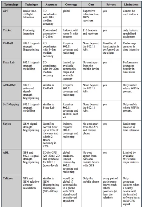
The following table summarizes the main characteristics of the different systems pre-sented (figure 2.10).
Besides its characteristics, the table presents the systems limitations. A quick anal-ysis of the table reveals that most of the systems use already existing infrastructures, which is also our approach to the system. The fact that these technologies are widely available, and can be explored at no extra cost to the users is a very appealing fact.
Our work combines several of the solutions of the various systems to obtain loca-tion estimates, as discussed in the previous secloca-tions. While most works only focused on one or two technologies at a time, our solution tries to use all available technolo-gies. Not only that, but by implementing several algorithms, it is possible to achieve adequate accuracy with possibly less energy consumption.
2.3. Summary
3
System Architecture
The Unified Cooperative Location System (UCLS) is a modular location system that can use any wireless technology available in a mobile device to estimate both sym-bolic and absolute location. UCLS includes an information sharing mechanism among mobile devices, allowing mobile devices to share location-related information. This mechanism allows a mobile device to obtain information from hardware it does not contain (e.g. GPS), or additional measurements for hardware it contains (e.g. GSM signal strength). This approach helps in improving location information accuracy.
The system promotes user privacy by establishing the location estimation on the device, without querying external entities every time a location estimation request is made. Since location sharing is made among nearby devices (usually up to 10 meters on mobile devices), and information exchanged is anonymous, location privacy is not significantly impacted by this mechanism.
The system has a very low entry cost, as it requires no additional hardware. A user simply needs to install the software on his mobile device, and start using it. UCLS was designed with the goal of being extensible. Thus, its modular approach allows to easily add support for new technologies and algorithms. Further control is achieved with this implementation, by deciding which technologies the user wishes to use at a time, controlling not only the energy consumption, as well as the required estimation precision. Algorithms can easily be added to the system, as well as additional location information storage and retrieval methods.
bulk. Gathered readings can be sent to the database, as well as retrieved, at any point in time the user wishes to do any of those.
3.1
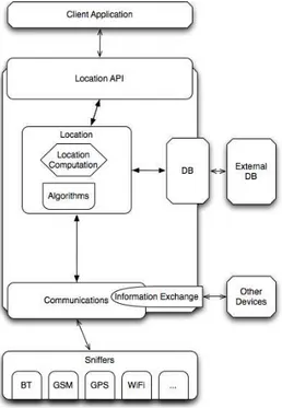
System Overview
The Unified Cooperative Location System (UCLS) has been designed to provide the programmer with a simple yet powerful location API. To achieve this goal, the UCLS Architecture consists of five modules and a collection of Sniffers, as depicted in figure 3.1. The Sniffers are simple background services, whose purpose is to obtain informa-tion that can be used for locainforma-tion (e.g. GPS informainforma-tion and wireless communicainforma-tions signal strength). This information is reported to the Communications Module. The Communications Module is responsible for aggregating the information from the snif-fers and delivering it to the other modules. This module also provides basic bluetooth communication primitives.
The Information Exchange Module uses the bluetooth service search and commu-nications primitives provided by the Commucommu-nications Module, to find nearby devices wiling to share location information. This allows for an easy method to share not only gathered location information, as well as more complex information such as location estimations, or relative distance estimations between the devices.
The Database Module provides primitives to store and read location information. It also allows the mobile device to connect to external servers or services. This is used mainly to share location information. In this case, the information stored locally acts as a cache of the more complete information stored in the server. The server can also be used to provide efficient location information data structures.
The core of the system is represented by the Location Module, whose function is to estimate the location of the device. To this end, this module controls the other mod-ules of the system, selecting which information to store or retrieve from the Database Module, to use the available location algorithms. This selection is based on the current configurations of the system.
Finally, the Location API Module allows the system to be used by a developer, integrating it easily on his developed location-aware application. The remainder of this chapter introduces each module of the system and how they relate to each other.
3.2
Location API Module
3.2. Location API Module
Figure 3.1: Unified Cooperative Location System Architecture
types: configuration, information acquisition and management and location estima-tion.
Listing 3.1: Location API Module
1 public interface LocationAPI{ 2 //configuration
3 public boolean activateTechnology(int TechId); 4 public void deactivateTechnology(int TechId); 5 public boolean activateAlgorithm(int AlgorithmId); 6 public void deactivateAlgorithm();
7 public boolean activateInfoExchange(); 8 public void deactivateInfoExchange();
9 public void setExternalServer(String serverAddress); 10 //information acquisition and management
11 public boolean activateLocationRecording(int seconds); 12 public void deactivateLocationRecording();
13 public void sendReadingsToServer(); 14 public void gatherReadingsFromServer(); 15 public RawData recordLocation(Location loc); 16 //location estimation
19 }
The API provides a set of simple configuration options to control what location mechanisms the system should use. An activation/deactivation call is available for every technology (GPS, GSM, Wi-Fi). If the associated hardware is locally available, the correspondent sniffer is activated. Otherwise, this technology can only be used if the information exchange mechanism is active and a nearby device willing to share this type of information is available.
To provide further configuration, a call is available to activate the system’s available algorithms. These algorithms are used for estimating the device location based on the currently available location information.
In addition to the aforementioned sharing mechanisms, and similar to the available calls to activate and deactivate certain wireless technologies, an activation and deacti-vation call is available for information sharing between similar devices. This should allow a device to obtain location information from another nearby device, including GPS and fingerprints information. Whenever this option is active, information gath-ering between nearby devices will occur for both mapping mechanisms (manual and automatic), as well as to estimate the current location if the used algorithm supports this feature.
To provide the user with the ability to map new locations using fingerprinting ap-proach, the API provides two simple methods for fingerprint acquisition: an automatic and a manual one. The automatic acquisition mechanism has an activation and a deac-tivation call. The acdeac-tivation call is initialized with a timer in seconds, corresponding to the interval between reads. While active, the system will gather the surrounding wire-less signal fingerprints whenever a GPS lock is available, and store that information in the DB Module.
The manual gathering mechanism is used mainly for symbolic or relative mapping construction, although if no local information is provided but a GPS is still available, the system will still record the observed data, since it will be interpreted as an abso-lute location reading. The API thus provides just a simple, manual call, which receives the location information (symbolic and/or relative), and gathers and stores one finger-print.
The Location API Module provides methods to upload or download location-related information to/from external devices or servers. For this purpose, two methods are available to either share the last gathered information with an external device/server or request new location information from an external device/server.
3.3. Database Module
and algorithm were used. The location estimation accuracy will depend on the avail-able technologies, location information databases and algorithms. An additional call is also available to simply scan a fingerprint and return it to the user.
3.3
Database Module
The Database Module (listing 3.2) is responsible for providing mechanisms for manag-ing and stormanag-ing location information. This location information can include Wireless fingerprints, antenna locations and mapping information. In the current prototype we are only using a solution based on fingerprints.
Listing 3.2: Database Module
1 public interface DBController{ 2 //configuration
3 public void setServer(String serverAddress); 4 //information acquisition and management
5 public void storeLocationInformation(LocationInformation reading); 6 public void sendData();
7 public boolean gatherServerReadings(); 8 //location estimation
9 public Iterator<LocationInformation> getReadings(int TechId,
10 String id);
11 public Iterator<LocationInformation> getReadings(); 12 }
The Database Module can be configured to connect to an external server, provid-ing extended functionalities to the information storage and retrieval mechanisms. By connecting to an external server, the location information previously recorded on the device can be shared with multiple users of the external databases. The device can also request the shared location information from the database server. This simplifies the process of obtaining the needed information for location estimation.
The second added functionality is the ability to use external resources to build and prepare efficient information for the device: instead of providing a list of location in-formation, more complex data structures can be created for the device, to simplify location estimation. This will allow the device to save time and energy, whenever it is necessary to search the stored information.
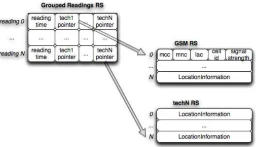
To gather the stored information, this Module supplies methods to access location information, providing an Iterator over the available information. The Iterator can ei-ther be over all of the available data, or a subset of the stored location information data. The iterator implementation will depend on the available Data Structures. Currently, an iterator is returned when a technology identifier and the identifier of the AP/Cell is shared. Then, every stored Location Information that contains the specified AP/-Cell is gathered and an Iterator to that collection is returned. This is only usable if a data structure is present to quickly return the needed results. Otherwise, the simpler method is used, which provides an Iterator for all the available location information in the Database.
3.3.1
Database server
A simple database server, accessed through web services interface (listing 3.3), was created, allowing users to store their location information. This service allows the in-sertion and retrieval of location data. Inin-sertions are made by simply sending the infor-mation to the database, together with a user identification and mobile device used to obtain the information. To retrieve location information, a call is available with several optional variables. These variables help the user to define if they want information from a specific user, mobile device or location.
Listing 3.3: Web Service Interface
1 public interface GathererImplWS{
2 public LinkedList<LocationInfo> getReadings(String user,
3 String device, LocationInfo location);
4 public void addLocation(LinkedList<LocationInfo> locations,
5 UserInfo user);
6 }
3.4
Communications Module
3.4. Communications Module
context of communicating with the sniffer, this module provides a function to open/-close connections and to send/receive typed data. Since each technology requires dif-ferent levels of control as well as difdif-ferent kinds of information gathering, each technol-ogy module must implement the getLocationInfo functionality call, which will return a gathered LocationInfo for that specific technology.
The Communications Module also implements a simple bluetooth services search call, used to find devices providing a requested service. This is used mainly for sharing information among mobile devices.
Listing 3.4: Communications Module
1 public interface ModuleCommunicator{ 2 //configuration
3 //information acquisition and management
4 public boolean openCommunications(int TechnologyId); 5 public void closeCommunications(int TechnologyId); 6 public int getInt(int TechnologyId);
7 public void sendInt(int TechnologyId, int intToSend); 8 public String getString(int TechnologyId);
9 public void sendString(int TechnologyId, String stringToSend); 10 //location estimation
11 public LocationInformation getLocationInfo(int technologyId); 12 public List<DeviceInformation> searchServices(String service); 13 }
3.4.1
Sniffers Communication protocol
To obtain location-related information, the Communications Module must contact the device’s available Sniffers. Each technology provides different types of information (e.g.: GPS provides longitude, latitude and altitude information, while Wi-Fi provides the SSID and Signal Strength information), as well as different methods of operation (e.g.: GSM location and signal information is always and instantly available to the device, whereas a GPS device needs an activation phase, followed by a satellite lock in order to start providing location information).
3.4.2
Bluetooth Communications
The Communications Module also includes a function to search for a specific service on the nearby bluetooth devices. Once the search is complete, the call returns the information needed to access the detected services. Additionally, methods for basic communication are available to the system, mainly the connection and disconnection methods, and the sending and retrieval of information.
3.5
Information Exchange Module
The Information Exchange Module (listing 3.5) is used by the Location Module to ob-tain location information from nearby devices. This module is only active when the mechanism is enabled. To share information, this module uses the available methods for service search and information exchange present in the Communications Module.
Listing 3.5: Information Exchange Module
1 public interface GroupShare{ 2 public void searchDevices();
3 public List<LocationInfo> requestData(List<int> technologies); 4 public LocationInfo requestLocation();
5 public List<LocationInfo> requestData(List<int> technologies,
6 int timestamp);
7 }
When active, the device will share wireless information with nearby devices that re-quest that information. To this end, the Communications Module retrieves the needed information, and supplies it to the device that requested the information. In the future, it would be interesting to add an option to select with which devices to communicate with.
Optionally, when a request for data sharing is made, a timestamp can also be shared, requesting the device to make the readings at a specified time. This allows the devices to perform a near-synchronous reading of all the available wireless information.
3.6. Location Module
devices are synchronized with the time of their respective Mobile Operators. Other more complex time synchronization mechanisms could be used in the future.
To request information from nearby devices, this Module uses the available blue-tooth service discovery in the Communications Module, to locate nearby devices avail-able for sharing. Then, the device simply needs to request the detected devices for their information. After receiving all the available data, including its own, it can return the received data to the Location module.
Since the communication between the devices allows for a simple information shar-ing, in the communication protocol it is possible to specify which information to obtain, including a location estimation.
3.6
Location Module
The Location Module (listing 3.6) is the core of the system. It is used by the Loca-tion API Module to provide the service to the Programmer. This module controls the System’s configurations and functionality. It uses the Database Module to store and retrieve information, and uses the Communications Module to gather and share real-time location information.
Listing 3.6: Location Module
1 public interface ULSController{ 2 //configuration
3 public boolean activateTec(int TechId); 4 public void deactivateTech(int TechId);
5 public boolean activateAlgorithm(int AlgorithmId); 6 public void deactivateAlgorithm();
7 public boolean activateInfoExchange(); 8 public void deactivateInfoExchange();
9 public void setExternalServer(String serverAddress); 10 //information acquisition and management
11 public boolean activateLocationRecording(); 12 public void deactivateLocationRecording(); 13 public RawData recordLocation(Location loc); 14 public void storeReading(Reading reading);
15 public Iterator<Reading> getReadings(Reading reading); 16 public void sendLocationInfoToServer();
![Figure 2.1: Example of locating object ’X’ with a 2D angulation, using angles relative to a 0 o reference vector and the distance between the two reference points (from [Bor01]).](https://thumb-eu.123doks.com/thumbv2/123dok_br/16520549.735628/26.892.287.559.838.1029/figure-example-locating-angulation-relative-reference-distance-reference.webp)
![Figure 2.6: Floor map where the RADAR system was tested (from [BP00]).](https://thumb-eu.123doks.com/thumbv2/123dok_br/16520549.735628/35.892.284.631.405.1074/figure-floor-map-radar-tested-bp.webp)
![Figure 2.7: Place Lab’s Architecture (from [LCC + 05]).](https://thumb-eu.123doks.com/thumbv2/123dok_br/16520549.735628/37.892.310.615.569.804/figure-place-lab-s-architecture-lcc.webp)
![Figure 2.8: Radio Propagation with ray tracing (from [JBPA06]).](https://thumb-eu.123doks.com/thumbv2/123dok_br/16520549.735628/39.892.285.648.134.333/figure-radio-propagation-ray-tracing-jbpa.webp)
![Figure 2.9: Absolute and Relative positions of mobile phones using Calibree (from [VPKE08]).](https://thumb-eu.123doks.com/thumbv2/123dok_br/16520549.735628/41.892.305.631.556.714/figure-absolute-relative-positions-mobile-phones-using-calibree.webp)