APS - European Centre for Mechatronics (Germany) RWTH Aachen (Germany)
University of Minho (Portugal)
Integrated Masters at Electronics and Computers Engineering
Thesis Work
Academic year: 2007/2008
<<February, 2008>>
Filipe Campos Meira Castro
Mobile robot electronic system
with a network and
micro-controller based interface
<<February, 2008>>
Filipe Campos Meira Castro
Mobile robot electronic system
with a network and
micro-controller based interface
0
Acknowledgements
Special regards own to all persons who made this project possible:
The director of the European Centre for Mechatronics: Prof. Dr.-Ing. P. Drews.
Special thanks to the project supervisor: Prof. Dr.-Ing. Günther Starke who always believed in the capacity to fulfil the work.
Special thanks to the project supervisor: Dipl.-Ing. Christoph Dreyer due his mentoring, guidance and kindness in all good and difficult moments of the process.
Special thanks to the supervisor: Prof. Dr. Fernando Ribeiro who always cleared doubts and uncertainties even from abroad. His advices were also essential to show a path and his availability was very kind.
1
Table of contents
Acknowledgements 0
Table of contents 1
1. Introduction and Goals 3
1.1. Thesis structure 4
2. State of the Art 6
2.1. iRobot Create™ Programmable Robot 8
2.2. MobileRobots's P-series 10
2.3. SWORDS 13
2.4. Talon robot soldiers shipped to Iraq 14
2.5. Termibot 15
2.6. 914 PC-Bot 17
3. Presentation and Implementation architecture 18
3.1. The robot 18
3.2. Block Diagram 19
4. Detailed working method 21
4.1. D.C. Motor 21
4.1.1 Composition of a D.C. motor 21
4.1.2 Principle of operation 22
4.1.3 Robot motors characteristics 23
4.2. PWM 24
4.3. Gearheads 25
4.4. Drivers 26
4.5. Encoder 29
4.6. Batteries 32
4.7. Step-Down Switching Regulator 34
4.8. AVR Programmer 35
4.9. I2C - TWI 36
5. Microcontroller Unit 41
5.1. Introduction 41
5.2. Header Files Structure 43
5.3. PIN List 44
2 5.4.1 atmega16.c 46 5.4.2 error_support.c 46 5.4.3 external_interrupt.c 47 5.4.4 generics.c 48 5.4.5 lcd.c 49 5.4.6 motor.c 50 5.4.7 timer.c 51 5.4.8 twimaster.c 52 5.4.9 usart.c 53
• “Old Version Protocol” to the communication from the Server Computer to
Atmega16 and Problems about it 56
• Protocol of communication from the Server Computer to Atmega16 57 • Protocol of communication from the Atmega16 to the Server Computer 60
6. Desktop Processing – C++ 65
6.1. Introduction 65
6.2. The Client 67
6.3. Class Client 67
6.4. Interface and applications 69
6.5. The Server 71
6.6. Class Server 72
6.7. Serial Port 72
6.8. Setup Window and Log Window 73
6.9. Interface and applications 74
6.10. Identical interface components between Server and Client 77 7. Schematic, Proto-board, Strip-board, PCB and hardware connections 79
7.1. Control hardware schematic 79
7.2. Proto-board and Strip-Board 80
7.3. PCB Schematic 83
7.4. 3D PCB 84
7.5. Hardware Connections 84
8. Software and Hardware considerations 86
9. Moot Points 88
10. Conclusion / Further work 92
Bibliography and WWW References 93
Table of figures 99
Table of tables 101
Table of flowcharts 102
Table of abbreviations 103
Attachments – Motor Specifications 104
3
1. Introduction and Goals
Nowadays mobile robots are expected to be a desire at several services to afford man facilities and increase safety in any kind of duties.
Mobility is a key issue in robotics and a challenging subject for any research and development. It combines cognitive capabilities focused on sensorial input and human interaction with intelligent control of the drive systems and requires real mechatronics engineering solutions to enable robust and reliable operation.
In the European Centre for Mechatronics [W1] mobile robots have been research subjects for years. A mobile platform with semi-autonomous functionality has been developed years ago. It has been used as a demonstration and test platform to study mobility and cognitive control.
In the University of Minho [W3] and RWTH University [W2] that kind of research is also important and the industry support gives a solid development sign to the institutions.
As the control system capacity on board of the vehicle has reached limits, a new system architecture with more powerful controller elements was planned to replace the old one.
In this context the key objective of the project was to design and develop a new embedded system capable of controlling the mobile platform drives using ATMega microcontroller technology.
4
• Introduction to vehicle system architecture and drives functionality • Introduction to microcontroller technology
• Development of a microcontroller hardware platform
• Development of a concept to control the drives and to enable driving modes
• Development of controller software
• Development of a user interface for remote control • Integration and functionality test
• Documentation
The work was performed in the labs of the APS - European Centre for Mechatronics.
The duration of the project was 5 months.
Technical assistance was provided by the APS project engineer Christoph Dreyer.
Supervisor in Germany is Prof. Günther Starke, Head of Research at the APS. Technical assistance and Supervisor in Portugal was provided by Prof. Dr. Fernando Ribeiro.
1.1. Thesis structure
This report is organized in the following order: • The State of the Art will be presented
• The Robot will be presented as well as respective block diagram of the system implemented
• An introduction of theory to D.C. Motors as well PWM signals, Gearheads, Motors Drivers and Encoders, Power regulators and Microcontroller programmers as well the I2C protocol will be done.
• Details of the Microcontroller unit will be presented next.
• The desktop programming (Server/Client) and (Server/Microcontroller) is presented.
5
• The schematics, Proto-board, Strip-board, PCB and hardware connections are shown as well.
• A chapter about software and hardware considerations is presented. • Finally the conclusions are presented.
6
2. State of the Art
Robots are more and more available for research and commercial applications. This robot is under research phase of development, as well as the control structure of the system.
The market shows some solutions of robots that are either autonomous or remote-controlled but robots with some autonomous capabilities are more common.
Remote-controlled robots can be found widely in military robots but service but tactical or service robots are usually autonomous.
Some chassis with only motors and without any control can also be find but comparing them to this one can lay to misunderstood since this robot has also software to the client and server and hardware like the microcontroller system and sensors.
Since this robot was developed under 5 month and is still under a development stage, it is not fair to make a direct comparison with other already finish robots. Even through the state of the art compares this work with most relevant similar projects.
Usually, preceding the autonomous development, a solid mechanic structure and control system is designed as well as low level programming to drive the motors and to make use of sensors. In this robot system those things were tested and the I2C communication support was included as well of serial and TCP/IP. The robot is remote control and has feedback regards to temperature, current, speed and position. The robot next development stage is to apply autonomous algorithms but that is overtaking within this thesis.
7
The proposed robot system has not, in the concern of this thesis, a specific application, even so, due to its powerful motor power, size and mechanicals part it can be compared with military device and also because this robot is, as many military robots, remote controlled but not yet autonomous.
This thesis was done in a 5month research, testing and production. The products below were done in a lot of years and probably with bigger team works, reason why probably these products are often provided with more sensors and automatisms controls as well as they are already in the market.
The existing robots are usually expensive and with lack of automations, reason why several approaches of a robotic platform are being devolved in several companies regarding the specific needs as size, cost, automatisms, simplicity.
Old robots platforms were design to a specific robot, and a change in the hardware implies a hard work wither in programming as in physical attachments. The system proposed is applied to this specific but can easily, at least some components, be connected to other mobile systems.
The proposed robot used I2C to avoid complexity at hardware and software level, the robot can easily grow with new hardware with only 2 wires, for communications with the controller, which decrease the complexity of adding new components. At the same time, the platform independent server computer can easily be equipped with USB components with “plug and play” capabilities.
8
2.1. iRobot Create™ Programmable Robot
Figure 1 shows the iRobot,Figure 1 – iRobot [W24]
According to [W24], iRobot is, since at least 15 years, a global leader in robotics, it has platforms for technological development and it is software is meat to developers to perform network based robotic behaviour.
As the robot system proposed in this thesis the low-level software infrastructure is done and future used need to project high level behaviours, loggers and debugging tools are also provided in both but the iRobot itself, as shown in figure 1, it is a small robot with upgrade capabilities as shown in figure 2 but to get this type of applications, is obvious that lot of software as well as mechanical and electrical hardware were developed in out of the iRobot package concern.
Like this proposed method, the iRobot Command Module also used the same family of the micro-controller, it used the ATMega168.
9
Figure 2 – iRobot pack [W24]
Figure 3 – the iRobot Packbot in Iraq [W25]
One of the examples of applications is the iRobot Packbot in Iraq as shown in figure 3.
“April 24, 2007 - The remarkable success of robots in Iraq and Afghanistan is now well documented. UAVs have proven invaluable at every level and robotic ground systems, primarily iRobot’s Packbot, have performed tens of thousands of missions and saved countless lives from the dreaded Improvised Explosive Device (IED).” [W25]
10
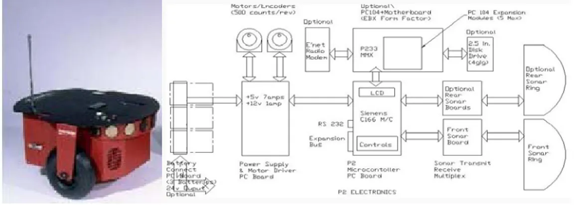
2.2. MobileRobots's P-series
Pioneers, PeopleBots, PowerBots and PatrolBots are physically different robots, from the MobileRobots's P-series, but with the same standard core architecture. [W26]
“Since 1995, Mobile Robots platforms have contained all of the basic components for sensing and navigation in a real-world environment, including battery power, drive motors and wheels, position / speed encoders, and integrated sensors and accessories. They are all managed via an onboard microcontroller and mobile-robot server software.” [W26]
Differently than the proposed platform independent system, these robots are called “Embedding Linux in a Mobile Robot”.
Figure 4 shows the Pioneer 2-DX picture and bloc diagram, which has similarities in the bloc diagram even so in a primitive way.
Figure 4 – ActivMedia Mobile Robot Pioneer 2-DX [W26]
Figure 5 shows the Pioneer 3-AT that is an evolution of the Pioneer 2-DX and it is rated at a 6,995$ cost.
11
Figure 5 – ActivMedia Mobile Robot - PIONEER 3-AT [W26]
“Pioneer 3AT is a mobile robotic skid-steer base with 4 drive wheels, microcontroller, motors, encoders, 1 battery, std. Pioneer software & no sonar, OS, ARIA, ARNetworking, MobileEyes, MobileSim, Mapper Basic & manuals; charger & ethernet or laptop connector not included.” [W26]
The bare P3-AT base with included ARIA software has the ability to:
Drive controlled by keys or joystick, plan paths with gradient navigation, display a map of its sonar and/or laser readings, localize using sonar (with optional laser upgrade), communicate sensor & control information relating sonar, motor encoder, motor controls, user I/O, and battery charge data, test activities quickly with ARIA API from C++ programs, simulate behaviors offline with the simulator that accompanies each development environment. [W26]
As the proposed robot, this one can communicate with a client computer through a “robot-to-laptop connector” but the microcontroller used is an ARCOS instead of the wise known AVR Atmega.
Technical specifications:
“The rugged P3-AT 50cm x 49cm x 26cm aluminum body with 21.5cm dia, drive wheels loves to run outdoors. The four motors use 38.3:1 gear ratios and contain 100-tick encoders. This skid-steer platform is holonomic and can rotate
12
in place moving both wheels, or it can move wheels on one side only to form a circle of 40cm radius.” [W26]
“A small proprietary ARCOS transfers sonar readings, motor encoder information and other I/O via packets to the PC client and returns control commands. Users can run the robot from the client or design their own programs under RedHat Linux with Motif or under WIN32 using their favorite C/C++ compiler. Our robotics development environments supply library functions to handle navigation, path planning and many other robotic tasks.” [W26]
13
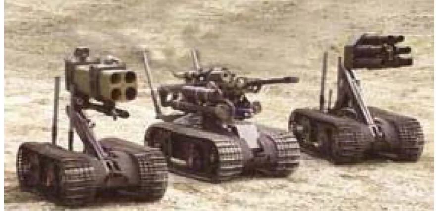
2.3. SWORDS
Figure 6 shows the Swords, one of the tested, applications to remote control robots
Figure 6 – Principle of operation [W22] http://www.gizmag.com/go/5098/
Swords, aka Special Weapons Observation Remote Direct-Action System, is a military robot system developed to a combat scene, it was finish in January 2006.
“The diminutive remote-controlled US$230,000 SWORDS machine shares the same base as the Explosive Ordnance Disposal (EOD) Talon robots which have been deployed in Bosnia, Afghanistan and Iraq. Unlike many of it is flying robotic (UAV) brethren, the weaponised Talon is not autonomous, being under the direct control of a soldier watching from up to a mile away through an array of cameras which can include both night and thermal vision.” [W22]
It makes use of AC power or lithium batteries and the control is deal over two joysticks, one for the robot platform and the other to the weapon.
To provide security over the communications a 40 bit encryption is implemented.
14
2.4. Talon robot soldiers shipped to Iraq
Figure 7 shows the Talon RobotFigure 7 – Principle of operation [W22] http://www.gizmag.com/go/3550/
US Army launch to Iraq and Afghanistan one hundred of TALON robots at the end of 2004. Those robots are equipped with off-the-shelf chemical, gas, temperature, and radiation sensors.
TALON robots can be used in missions as clearing live grenades to neutralizing mines in shallow water, and can be adapted for small mobile weapons systems for military purposes. [W22]
“The TALON is a general-purpose modular robot with a versatile 64-inch pincer arm. It is controlled through RF or a fibre optic link from an attaché-sized operator control unit (OCU) or wearable OCU. On the ground the TALON can reach a vehicle speed of 6.6 km/h and last a four-hour run time. Mounted on the TALON robot are:
• Smiths APD 2000 advanced portable chemical agent detector. • Draeger Multiwarn II gas detector.
• Raytek Raynger MX4+ temperature sensor. • Thermo FH40GL radiation detector.” [W22]
15
2.5. Termibot
Termibot, as shown in figure 8, is a remote-controlled robot that makes use of thermal imaging to detect and eradicate termites.
Figure 8 – Termibot [W28]
Termibot was release in May,2007 to reach places where human pest controllers can't go. [W28]
“When a telltale heat or moisture signature is detected, Termicam breaks termite nests open to confirm the infestation, then pumps pest control chemicals directly into the source. It is an ingenious non-invasive pest control device - but its appeal won't be limited to exterminators.
"It is basically a remote controlled robot that can fit into confined spaces," says Rice, "it carries a video camera and lights so the operator can see where it is going and steer it around obstacles. It can go over on a fairly good angle and right itself if necessary." When the thermal or moisture signature of a termite hotspot is detected on one of the device's two LCD screens, the Termibot uses a probe to break open the termite nest, exposing and video recording the insects as they scuttle to repair the breach. The operator is then able to inject pest control poisons directly into the termite colony, an effective eradication
16
leaving minimal toxic chemicals around the area in comparison to spraying.” [W28]
"It is currently controlled via a long cable," Rice tells us, "but we'll have it fully remote once we've finished further testing. We're currently field testing it under houses, it is available to all our franchises but because we're busy expanding and franchising around the world, it won't be ready to go to market until later in the year." [W28]
“Rice says he's already had several enquiries from outside the pest control industry; the remote control thermal camera will be of interest to anyone who needs to use thermal imaging in confined spaces. Once client in Brunei is looking at having it lightly modified to act as an air conditioning duct cleaner, and Rice sees applications for the Termibot in sewage and water tunnel investigations, electrical equipment testing, military and bomb disposal applications, and even search and rescue to detect the heat signatures of people trapped under snow or rubble.” [W28]
17
2.6. 914 PC-Bot
Figure 9 – 914 PC-Bot [W27]
Figure 9 shows the 914PC-Bot, it is a $5,000 robot.
“The 914 can serve as a "networked, mobile sensor platform for RFID readers, hazmat detectors, and access management devices." The company suggests, "Now you can move the sensor, vs. the asset."
The 914 stands 21-inches tall, and weighs about 55 pounds (25kg). It has a two-wheel drive train with two "caster ball" wheels, each powered by a DC stepper motor. Other sensors include a camera in the head unit, and a sensor array comprising eight IR sensors, presumably used for obstacle avoidance. The 914 is powered by twin 12-volt lead-acid batteries, and comes with a charger.
“Since the 914 is really just a standard PC trapped in a robot's body, it can run any standard PC operating system. WhiteBox Robotics supports Linux on the device, as well as Microsoft's Robotics Studio. When used with Linux, the company also appears to support the open source Player/Stage robot and sensor programming library.” “[W27]
18
3. Presentation and Implementation architecture
This chapter will present the robot and its block diagram to provide an understanding of the general structure of the robot system architecture and the robot components.
3.1. The robot
The figure 10 shows the robot: it is a solid multi terrain tank style robot and it can be seen the two chosen motor drivers, a DC converter, the microcontroller display and the batteries that provide power to the microcontroller system as well as to the motors. The motors and the encoders can also be seen.
19
The tank is a Remote Operated Vehicle (ROV) and it is in the process of being converted into an autonomous robot.
3.2. Block Diagram
The block diagram is shown in figure 11 displays the way the several components are connected.
Figure 11 – Block Diagram
As shown, the system is based in multiprocessor, it is composed by two computers, one is the Client and the other one is the Server, a microcontroller as well as the drivers, encoders and a display.
20
Client and Server based architecture of this robot inherits that its interconnection is provide through a wireless network to make the robot control without any wires.
Tasks that are likely to be critical to performance and safety are implemented in a micro-controller. The system robustness is this way increased comparing to robot systems based only in computers [B2].
The atmega16 microcontroller is the center of the hardware of the robot: the display connected to it gives feedback of the microcontroller states and has an important duty about diagnose, repair and maintenance of the robot. For example, if a miss to connection of the motor drivers to the I2C bus occurs, it will show a message saying “Motor Left: Error, Motor Right: Error”.
Status monitoring of the system parameters during an operation cycle can be also archived with the display.
The Server connects to the Atmega16 microcontroller over RS232 protocol.
Atmega16 microcontroller code was written in C language but C++ language is used to Server and Client computer code.
The connection between the DC regulator and the Atmega16 microcontroller and the encoders and the power side of the motor drivers is not represented in the pictures to avoid confusing mesh of wires in the schematic.
The physical picture of the robot and the interconnections of the several components of the robot system were briefly presented in the block diagram as well as the communications protocols between them.
21
4. Detailed working method
This chapter will present the electronic and mechanical components of the robot system as well of theory used to deal with them.
4.1. D.C. Motor
D.C. motors are used rather than other designs because they are smaller and have high efficiency. Furthermore, the D.C. motor has a very high start-up torque and they absorb sudden rises in load easily [W22].
DC motors are also simple to control; even so they are heavier and less efficient than induction motors.
The use of this type of motors is also efficient in this case because the robot is powered by batteries which provide the same type of current that these motors need, so power converters are avoided and the consequent loss of efficiency is spare.
4.1.1 Composition of a D.C. motor
22
Figure 12 – Composition of a D.C. motor [W22].
The motor used by this robot has this composition [W22] and has an additional gearbox at the shaft.
The stator has the cover of the motor as well as the magnets that create the stator magnetic filed [W22].
The rotor is mainly formed by a metal carcass carrying coils and the commutator that selects the coil through the electric current will flow. The commutator has the duty of transforming the induced altering tension into a continuous tension [W22].
4.1.2 Principle of operation
The principle of operation of a D.C. motor is based on rules of electromagnetic attraction [W22].
The rotor is energised to act as an electromagnet with the polarity given by the current flow direction [W22].
The figure 13 shows that D.C. motors have two magnets fields, one of them is fixed(stator) and the other one is physically movable [W22].
23
Figure 13 – Principle of operation [W22]
A torque is created to make the poles of the rotor align to the poles of the stator. This attraction and repulsion between the magnetic fields makes the rotor, which is the movable part, spin, and then the brushes are constantly breaking and making contact with the commutator [W22].
The maximum torque is achieved when the axis between the poles of the stator is perpendicular of the poles of the rotor [W22].
“The rotor coils are then energised and de-energised in such a way that as the rotor turns, the axis of a new pole of the rotor is always perpendicular to that of the stator. Because of the way the commutator is arranged, the rotor is in constant motion, no matter what its position. Fluctuation of the resultant torque is reduced by increasing the number of commutator segments, thereby giving smoother rotation.”
[W22]
To change the spinning direction of the motor one of the magnetic fields must exchange, since the stator has permanent magnets, the way is to invert the rotor magnetic field. This can easily be done by changing the polarity of the tension applied to the rotor coils, the direction of the current will this way be reversed as well as the rotation direction [W22].
4.1.3 Robot motors characteristics
The robot has two motors provided from the manufacture ENGEL, the series is GNM5480E and the motors are typed “Permanent Magnets, Direct Current”
24
they are coupled with gear-heads and the main characteristics can be seen at table 1.
Full table of characteristics can be find in the attachment “Motor Specifications” as well as the dimensions.
Nominal voltage UN 24 Volt
Nominal output power P2 250 W
Efficiency η max 85 %
No-load speed no 3,267 rpm
No-load current Io 1,435 mA
Speed constant kn 137 rpm/V
Nominal speed 3,000 rpm
Motor operating temperature range –20 to 100 °C Table 1 – Robot motor characteristics
4.2. PWM
A powerful and common method to control D.C. Motors over a microcontroller is by using of Pulse Width Modulation (PWM) signal [B1].
The PWM signal consists in a square wave and varying its duty cycle will provide a varying mean power applied to the D.C. motor [B1].
25
Figure 14 – PWM signals of varying duty cycles [B1].
4.3. Gearheads
In applications, when high speed is not as important as the involved torques, it is usual connected a gearhead to the motor [W21].
With a gearbox the motor binary can increase and the startup effort is soften.
To avoid degradation and damage of the gear/pinion several gears are used instead of only one, this way the forces are distributed and the material of which they are done can be “soften”. The lubrification degradation is also archived this way. [W21]
To make a description of what and by what is composed a gearhead is necessary to say that it has satellite gears and an annular gear. This one usually forms the gearhead case on the outside and has gear teeth cut in the inside diameter. The satellite gears are carrier plates with pins that fit the inside diameters of the satellite gears. Figure 15 illustrates a single-stage planetary gearhead having three satellite gears. [W21]
Figure 15 – Gearheads [W21]
The gear shaft is attached directly to the motor shaft and then a bearing couples the driven load.
The gearbox is selected depending on the maximum required torque and the duty cycle [W21].
26
The direction of rotation of this gearhead output shaft is the same as the input one. One of the disadvantages of this gearhead is the high noise but, besides that, they are relatively smaller than other types found in the market to the same operation conditions. [W21]
It increases also loss of efficiency and weight to the system, which could be a problem in a platform feed by batteries.
The lengthening of the annular gear/case and multiple stages stacking can allow high gear ratios. [W21]
The gearheads series are “G6.1” and they are of planetary type; it is rated at a 16.8:1 ratio and 70% of efficiency at either clockwise or counterclockwise direction, the torque is 11Nm.
4.4. Drivers
The medium/high current motors of the robot must be able to run in both directions and in variable speed, to archive that, either an H-bridge should be projected or, to reduce the time to market, a solid driver should be chosen.
Because the actual markets provides a reasonable range of driver solution to different applications and are price competitive, the conclusion is that the best s solution is to acquire one. It spares time because that kind of project, involving high currents, from the practical point of view would increase the number of difficulties which wouldn’t provide enough time to take the project this far.
There are three drivers pondered:
27
Figure 16 – RN-VNH2 Driver [picture provided by the manufacturer datasheet]
This driver [16] does not provide the necessary 250W, the motors need. But it was used for testing and experimenting, using a smaller motor.
The atmega16 was programmed to provide the PWM signal [Chappter 4.2. ] to the driver. The direction, speed and acceleration ramps were made and tests about controlling those values with computer were made as well, those tests involve the use of the USART (Universal Synchronous Asynchronous Receiver Transmitter) to perform communication between atmega16 and one computer.
The work before described was ponder later because, within the project, when doing research about drivers and robot controls technologies a protocol called I2C came up.
The protocol will be explained later on another chapter [chapter 4.9. ], but the choices about the driver were now about two divergent drivers: one from Sabertooth [17] or the MD03.
The “Sabertooth 2x10” is a driver capable of driving the robot motors with the software that was done and tested with RN-VNH2 Driver.
28
Figure 17 – Sabertooth Driver [W12]
The MD03 is the driver shown at figure 18 and it is a driver capable of “talking” I2C and up to eight MD03 modules can be connected (switch selectable addresses) to a system [W23].
The MD03 was chosen because the I2C capabilities matched the project intention of a modular system design and has the power capabilities that the system requires.
Figure 18 – MD03 Driver [W23]
In this robot the addresses were chosen with no specific criteria and they can be seen at table 2.
Motor Right Motor Left
Adresses 0xB0 0xB2 Table 2 – MD03 addresses of left and right motor
29
“I2C communication protocol with the MD03 module is the same as popular eeprom's such as the 24C04.” [W23]
The MD03 has 8 registers numbered 0 to 7.
The reading operation of the registers is done in the following order: 1. sending a start bit
2. sending the module address with the read/write bit low 3. sending the register number to be read
4. sending then a repeated start
5. sending the module address again with the read/write bit high [W23]
4.5. Encoder
Nowadays to make possible the use of modern motion control techniques, values representing the locations of the robot are needed. To do that, the spin of each motor of this robot must be log.
Devices, that provide the knowledge of where the robot motors are, make possible to synchronize the movements of the robot and at same time gives feedback to the control system, to act if some kind of behavior is not reached.
This robot has two incremental encoders that are used to precise how much is each motor running and they provide the speed of each motor after some computation.
The system of an incremental encoder is usually based on transmitting/reception method:
One disk with holes is in the middle of the transmitter and the receiver.
The transmitter has a stationary light source and the receiver has two stationary light detectors,
30
The disk is mounted at the shaft. As the disk rotates, the holes in it make the receivers to get the light each time the hole is aligned with the light transmitter. Figure 19 can illustrate this process:
Figure 19 – Encoders signals [W20]
The outputs of this system are two square wave signals representing the number of holes that are reached between the transmitter/receptor, typically one output is called channel A and the other one is channel B and an extra channel usually called channel Z is often included to detect the “once per revolution index mark”.
A visual perspective of the signals above described can be seen in figure 20.
Figure 20 – Encoders signals [W19]
“The position of the two detectors is important. As one senses a change from dark to light, the other will not sense a change or transition. Because of this physical arrangement, two detectors give four transitions per division on the disk and each transition occurs at a unique angular position on the shaft. By
31
counting the transitions, it effectively multiplies the line count by four, hence the name quadrature (X4) multiplication. “ [W18]
To sense the direction of rotation the encoders have two channels 90 electrical degrees out of phase. A rising edge of the square wave indicates one direction, and the falling edge of the square senses the other direction.
To get the direction, each encoder, as shown in figure 21, was also coupled to a D type flip-flop. With channel A as flip-flop clock input (clk) signal and channel B as the input data (D) signal is possible, using the combination of these two signals, to obtain the output of the flip-flop (Q) representing the direction of rotation. This output (Q) is connected to an input pin of atmega16 so the microcontroller can know if pulses are to be increased (Output of the flip-flop is 0) or decreased (Output of the flip-flop is 1).
Combination:
Q Æ signal B low at signal A is rising edge /Q Æ signal B high at signal A is rising edge
To make use of these sensors, a connection between channels A of each encoder was connected to an external interrupt of atmega16 which is programmed to catch rising edges and make the digital count of the pulses.
Figure 21 – Encoders Flip-Flops [W19]
32
Figure 22 – Robot encoders
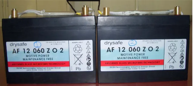
4.6. Batteries
The batteries used in this robot are Lead Acid batteries, they are popular because they are easy available, rechargeable and inexpensive.
The problem is they are very heavy and large but, in this case, that is not a huge problem because the tank is powerful and big enough to carry them, even so that is a problem to equation if the robot goes on the market or in further improvements.
Another problem is the loose of charge even if they aren’t in use and high discharge rates will be translated in a short time battery life.
There are three existing main types of lead acid batteries: Wet Cell, Gel Cell, and Absorbed Glass Mat (AGM). They are mainly distinguished by the price, degrade, and deep cycle needs.
The Gel Cell batteries were chosen and they are best used in very deep cycle applications even so the AGM batteries provide a greater life cycle. They don’t need maintenance and don’t flow out acid.
33
“80% of all battery failure is related to sulfating build-up. This build-up occurs when the sulfur molecules in the electrolyte (battery acid) become so deeply discharged that they begin to coat the battery's lead plates. The buildup will become so bad that the battery will die.” [W13]
It is important to know and have in mind some things about lead acid batteries this way preventing battery failure:
• The first point to remember is not to make a partial recharge of the batteries, all charges should be integral done to its full potential. [W13]
• A second point, and also a very important one, is to recharge them often because without being used for a long time these batteries will slowly discharge internally. [W13]
These robot batteries are serial connected to make a 24V power supply, that connection can be seen on Figure 23.
The type is Exide and they are rated as gel cells which are a maintenance-free motive power batteries technology as well as they are robust, safe and reliable Low self discharge is also archived by those.
34
4.7. Step-Down Switching Regulator
A regulator was needed to convert the 24V from the batteries to a regulated 5V to feed the microcontroller, encoders and the other components.
The regulator component is a LT1076 that is rated at 2A, is a monolithic bipolar switching regulator and requires only a few external parts for normal operation. It has built-in power switch, oscillator, control circuitry, and all current limit components.
The classic positive “buck” configuration was adopted and the switch output is specified to swing 40V below ground which is perfect to the 24V of the robot because it is in the middle of the rated range.
The schematic of the regulator can be seen in the figure 24 and the board in figure 25.
35
Figure 25 – Regulator Board
4.8. AVR Programmer
To flash the microcontroller with applications, a programmer is needed. The microcontroller chosen for the project is part of AVR family.
At chapter 5. the microcontroller will be explained but, in this one, only the programmer will be discussed.
The circuit presented on figure 26 and PonyProg flash program [W6] was chosen because it is very cheap and can be easily hand-made done.
The problem of this circuit is that it needs to be use together PonyProg [W6] to enable flashing the microcontroller and PonyProg can use RS232 but “USB to RS232” adapters often don't work or are very slow (more than 10 minutes to program) to avoid USB adapter the solution to a laptop could be a PCMCIA or a PCI adapter that native emulate a COM port but a PCMCIA card was tested and even so it was very slow.
So, to flash the microcontroller with this programmer, a desktop computer, with native COM port, was used. This approach will not allow a remotely programming of the microcontroller of the robot and beside that JTAG and AVR Studio integrations are not possible.
In the future, to provide a fast remote programming of the microcontrollers the “Atmel AVRISP MK2” or “AVR Dragon” programmer would provide better
36
results as well as other advantages as the AVR Studio Integration, USB Serial In-System Programming and the JTAG Support (“Hardware debug” with “AVR Studio” in real time, which means that the instructions done with AVR Studio debugger can automatically be seen on the hardware)
The board can be seen on figure 27:
Figure 26 – “SI-Prog” Programmer Schematic
Figure 27 – Programmer Board
4.9. I2C - TWI
One of problems of the robots is that to provide more intelligence to them more and more sensors are added and that implies more and more wires.
To minimize that, I2C (Inter Integrated Circuit) also known as TWI (Two Wire Interface) [W15] is the communication protocol chosen because it can easily link multiple devices together with only two wires each. [W17]
37
The devices have a built-in addressing scheme to be distinguished and avoid the need for chip select or arbitration logic which can provide simplicity to the system as well as less money spent in extra hardware such as multiplexers and logic chips.
Standard I2C devices operate up to 100Kbps but fast-mode devices operate at up to 400Kbps and 3.4Mbps can be reached with the version 2.0 high speed mode.
Almost all available I2C devices can operate at speeds up to 400Kbps.
I2C provides good support for communication with various devices. On-board peripheral devices can be accessed intermittently; it is a simple, low-bandwidth, short-distance protocol.
Philips originally developed I2C for communication and due patent concerns Atmel use the name TWI (Two Wire Interface) instead of I2C.
Several I2C-compatible devices are manufactured by several companies and can be found in embedded systems. Some example are eeproms, thermal sensors, and real-time clocks, video decoders and encoders, audio processors, displays, motor driver, etc.
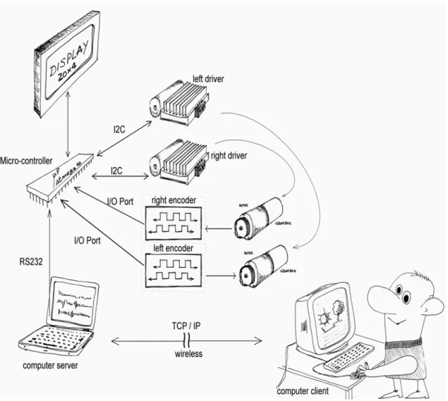
The figure 28 shows the typically I2C interconnection system:
38
Below, the figure 29 shows the specific interconnections with the I2C bus: the microcontroller is the master of the I2C Bus and both drivers are I2C slave devices.
The two resistors are called “pull-up resistors”, they need to be present on the clock line (SCL) and on the data line (SDA). They are used to do the interface between different types of logic devices and they ensure that the circuit assumes the default value when no other component forces the line input state. Since the chips are design often open-collector, the chip can only pull the lines low and they float to VDD otherwise; this way, the master can sense if a simultaneously transmitting is happening, letting the pin float and sensing the line, if the line is still at VDD, probably, no transmission is being done from other device. [W17]
The programming of atmega16 master software is described at chapter 5.4.8
Figure 29 – Robot I2C interconnection system
The two I2C signals are Serial Data (SDA) and Serial Clock (SCL). I2C matches the Master/Slave topology.
I2C
SDA
39
The I2C Master is the device that can start and stop communications and has usually the duty of controlling the clock.
An I2C Slave is a device that is addressed by the master. When the master asks a slave for data, the slave has the possibility to hold off the master in the middle of a transaction using “clock stretching” [W17] (the slave keeps SCL pulled low until it is ready to continue). This makes synchronism of slow slave devices possible but most I2C slave devices don't use this feature.
It is duty of every I2C Slave to monitoring the bus and responding only to its own address.
The I2C protocol supports multiple masters and multiple slaves.
The transmitting protocol inherits the data sending of each byte, start with the MSB (most significative byte).
Figure 30 shows a typically communication between a master issuing the start condition (S) followed by a 7-bit slave device address to start a communication with a Slave.
The eighth bit after the start (read/not-write) is used to signal the slave if the master will send more instructions (Slave will receive more data) or if the master is ready to receive data (Slave can transmit data).
After each byte sent by the Master, the Slave must reply with an ACK bit to signal the reception of the previous byte.
This 9-bit pattern is repeated if more bytes need to be transmitted.
40
The issue of the stop condition (P) is done instead of the ACK at the end of a master reading transaction (slave transmitting).
If a master write transaction (slave receiving) is being performed, the master issue the stop condition (P) when it receives the last ACK of the data sent.
This chapter presented the electronics, some mechanical components were also presented as well of characteristics of the drivers and I2C.
41
5. Microcontroller Unit
In this chapter the microcontroller software is about to be presented in order to provide understanding about the microcontroller unit and its duties.
The protocol of communications used from the server to the microcontroller and from the microcontroller to the server will also be presented.
5.1. Introduction
There is a large variety of microcontrollers on the market. The Atmega16 belongs to AVR family and was the microcontroller chosen to make a new embeddable system capable to control the I2C motor drive system, to read the encoders and to give local feedback through a display and to perform communications with the server.
Other microcontroller family could be chosen to the robot system but the cost of the device programming must not get high as well of the compilers that must be freely available. 8051, Microchip PIC®, and Atmel AVR® were possibilities that matches the criterion.
The traditional 8051 has a simple architecture and it is familiar to most embedded engineers. The amount and quality of tools and sample source code available is ample but it is common that each manufacturer provides proprietary features and migration from one variant to another usually implies new programmers. The typical architecture of some models are standard for several manufacturers but those don’t have engrossing stuff like A/D and D/A converters, I2C, In-circuit programming, etc. [B2] That lack of standardization
42
makes and the problems with upgrading do not meet to the project objectives so it was placed apart.
A PIC microcontroller were considered an expensive solution that the Atmel AVR (The PIC official programmer(PICstart Plus) cost 3 times more than the AVR one(STK500) [B2]).
AVR microcontroller is manufactured from Atmel [W4] and its family is largely used worldwide so it is easy to get access to libraries or fragmented source codes all over the internet [W10] and its versatility makes possible to make use of several different features and to perform simple future migration of the source code within microcontrollers of the same family and it is possible to use different compilers and different programming languages.
Atmega16 has a number of features which make it very good to this project. It has 3 Timers, 4 PWM channels, I2C also known as TWI(Two wire interface), 8 ADC’s, USART, SPI and 32 I/O ports [W9]. The pinout can be seen of figure 31.
Figure 31 – Atmega16 pinout [W9]
The editor and debugger used was “AVR Studio” that is freeware and has a very good and powerful debug mode and simulator [W11] .
43
The language used is C, the medium level rate of this language makes a good power/control ratio which makes the robot programming flexible.
The way the program was made intended to have modularity and an easy to use structure for future programmer who will improve the robot.
The modularity was made by using of many files, each one giving its own main functions, even so they can depend on the others, for example: the USART (Universal Synchronous Asynchronous Receiver Transmitter) functions uses the MOTOR functions after decoding a command sent by the computer Server program.
Each file can be compiled separately and then linked together. This provides a saving of time since it is not necessary to recompile the complete application when making a single change but only the file that contains it.
A systematic way of writing the program was chosen to provide an easy reading of it.
All include files that some file needs is specified at the header file (.h) The main variables and the external ones are also included at the header file (.h)
Only the local variables are at respective “.Cpp” file
This chapter will present each one of the several “.Cpp” files and flowcharts of some functions.
5.2. Header Files Structure
44
So each header file has the same template layout which consist in define, at first include files, follow by constant definitions and variables used, at last, the functions prototypes are declared.
5.3. PIN List
The list of all currently used PIN’s as well as a description is presented at table 3, even so, some might be described during this chapter.
PIN Variable Name Description PIN DDR PORT
error_led1_PIN LED signal of error nr. 1, 7 DDRA PORTA error_led2_PIN LED signal of error nr. 2 7 DDRD PORTD encoder0_direction_PIN Encoder right Direction
Signal,
Set this pin high means running forward and set this pin low means running backward.
4 DDRD PORTD
encoder1_direction_PIN Encoder left Direction Signal,
Set this pin high means running forward and set this pin low means running backward.
5 DDRD PORTD
INT0 Encoder right Channel
Signal,
Used to count pulses from the encoder
2 DDRD PORTD
INT1 Encoder left Channel
Signal,
45
Used to count pulses from the encoder
LCD_DATA0_PIN Pin for 4bit data bit 0 (Least Significant Data Bit)
0 DDRA PORTA
LCD_DATA1_PIN Pin for 4bit data bit 1 1 DDRA PORTA LCD_DATA2_PIN Pin for 4bit data bit 2 2 DDRA PORTA LCD_DATA3_PIN Pin for 4bit data bit 3 (Most
Significant Data Bit)
3 DDRA PORTA
LCD_RS_PIN Pin for RS(Register Select) line
This pin determines whether the data you're about to write is a command or a data byte
4 DDRA PORTA
LCD_RW_PIN Pin for RW(Read/Write) line
Set this pin high to read from the display. Set this pin low to write to it.
5 DDRA PORTA
LCD_E_PIN Pin for Enable line,
This line works to clock in data and commands.
6 DDRA PORTA
SDA I2C/TWI Data line 1 DDRC PORTC
SCL I2C/TWI Clock line, It is
used to synchronize all data transfers over the I2C bus
0 DDRC PORTC
Table 3 – All Pin List
5.4. Files
46
5.4.1 atmega16.c
Atmega.c is the main file of whole microcontroller application.
The initializations of the modules (error support, usart, lcd, encoder, i2c, timers, interrupts and motor drivers) are done at the main file (atmega16.c), reason why atmega16 header file connects all needed modules, as shown in figure 32.
After all initializations, the program will run in an infinite loop waiting for any command sent over the serial port and waiting for the timer to perform some computation (Virtual Heart Beat, Sending Sensors Data).
5.4.2 error_support.c
This module is used to help the programmer at the debug stage. The features provided are the basic turn on and turn off of leds. At the moment two LED’s are defined:
47 LED Number 1: PORTA.7 LED Number 2: PORTD.7
It is very easy to include this file in any other and give them this debug capability and to increase the number of leds or change its port connections!
The functions provide are:
void error_support_init(void); Initialization of the ports (output).
void error_on(int led_number); Turn a LED On.
void error_off(int led_number); Turn a LED Off.
5.4.3 external_interrupt.c
This module is used for the encoders.
The robot has two quadruped encoders, each one is connected to an External Interrupt and each time a transition is made by any encoder the microcontroller will count it.
Derived from the asynchronous and unpredicted pulse occurrence, an external interrupt was configured, this way this “time-critical” operation is separate from the main program execution [B1].
Generically, two main types of external interrupts could be implemented:
48
Figure 33 – Level- and edge-sensitive interrupt signals [B1]
Level-sensitive interrupts are attended at either a low-level or high-level [B1]. Edge-sensitive interrupts are attended at a transition that can be defined to be rising edge or falling edge sensitive interrupt [B1].
A edge-sensitive approach was chosen because even if, in theory, a pulse is skipped when a subsequent interrupt occurs [B1] (practically the test with both robot wheels running at same speed shown that the processor catch all pulses); an approach with level-sensitive would certainty provide worth results because the Level sensitive interrupt suspends other processing during all level time [B1] and pulses would be missed if both wheels were running at same speed.
Another PIN is defined, for each encoder, at the header file and the purpose is to know whenever the encoder is running forward or backwards and so the microcontroller knows if it has pulses to be increased or decreased respectively. The way those PINs gets its state was detailed described at chapter 4.5.
5.4.4 generics.c
This module provides two functions:
void delay_ms(unsigned short ms); Used for make a variable delay
49 void wait_until_key_pressed(void);
Used to read a switch, actually is define to read PIND.2.
5.4.5 lcd.c
This module implements a free to use HD44780U LCD library; the author is Peter Fleury [W16], after changes of the PINs options and adjustments to use 4 PIN data transfer and after prepare it to a 20x4 LCD, it looks just perfect to communicate with the LCD.
The main functions are:
void lcd_init(uint8_t dispAttr);
Initialize the display and select the type of cursor.
void lcd_clrscr(void);
Clear the display and set cursor to home position.
void lcd_gotoxy(uint8_t x, uint8_t y); Set cursor to specified position.
lcd_puts(const char *s);
Display string without auto linefeed.
A function to display number was also added: void lcd_puti(int int_value);
Display int value.
As an example of application, the following commands: lcd_gotoxy(0,2);
lcd_puts("MD03 Right = OK!!");
Are used, (after the lcd inicialization) at the start of the main program, inside of a function to test the communication to the motor drivers
50
(motor_drivers_init_test();) and the result is the display writes "MD03 Right = OK!!” at the 1st column and 2nd line, providing that feedback to the user of the robot.
5.4.6 motor.c
This module functions respect to the motor drivers, the main functions are below described and interconnections can be seen at figure 34:
void motor_drivers_init_test(void)
It is used to make initial test to the motor drivers. Basically it tests the I2C communication, and updates the variable motor_driver_error with the result of the test. That variable is also useful to avoid sending commands to the driver when it is not connected, that way the microcontroller doesn’t halt trying to send commands to a disconnected motor driver and so tests with others sensors and the computer can be made without these drivers. A feedback is also archived through the lcd.
void break_motor(void)
It is used to provide a simple a fast way to break the motors.
51
5.4.7 timer.c
The functions related to the timers are implemented in timer.c / timer.h files.
As usual at embedded systems [B1], when the timer is activated, the program will change its flow to the function SIGNAL(SIG_OVERFLOW1) and when it is completed it returns to the place where it was before.
(SIG_OVERFLOW1 is the address of the interruption vector respect to the
timer/counter 1 overflow)
At figure 35 the interconnections with this module can be seen, the purpose of the timer is to:
• Calculate the speed of each motor of the robot.
• Deal with the “Virtual Heart Beat” a.k.a. “emergency ping”. • Automatically send the sensor data to the Server.
void starttimer1(void);
Is used to start timer1.
void stoptimer1(void);
Is used to stop the timer1.
A “Virtual Heart Beat”, is identified at the code as an “emergency ping”, was created between Server/Client and Server/Microcontroller to avoid loss of control to the robot. In the microcontroller concern, it can be described as a command that is sent to Server every 2 seconds.
The Server when receives it has the duty to resends that command.
If, after four seconds, no acknowledge of the previous ping was received then a command to stop the motors is sent by the microcontroller to avoid damages caused by an uncontrolled robot.
52
5.4.8 twimaster.c
This module implements a free to use I2C library and the author is Peter Fleury [W16].
It is used to provide functions to communicate with the I2C devices.
The main functions provided in this library are:
void i2c_init(void);
Initialize the I2C master interface. Need to be called only once for each device.
void i2c_stop(void);
Terminates the data transfer and releases the I2C bus.
unsigned char i2c_start(unsigned char addr);
brief Issues a start condition and sends the address and transfer direction; returns 0 if the device is accessible or 1 if failed to access device.
unsigned char i2c_rep_start(unsigned char addr); Figure 35 – timer.h interconnections
53
Issues a repeated start condition and sends the address and transfer direction; returns 0 if the device is accessible or 1 if failed to access device.
void i2c_start_wait(unsigned char addr);
Issues a start condition and sends address and transfer direction.
unsigned char i2c_write(unsigned char data);
Sends one byte to I2C device; returns 0 if the writing was successful or 1 if the writing process fails.
unsigned char i2c_readAck(void);
reads one byte from the I2C device, requests more data from device and returns that byte read from I2C device.
unsigned char i2c_readNak(void);
reads one byte from the I2C device; the reading is followed by a stop condition and returns the byte reading from I2C device.
As an example of application, the following commands:
i2c_start_wait (MD03_l+I2C_WRITE); // set device addr. & write mode i2c_write(addr_direction); // write address
i2c_write(0); // ret=0 -> Ok, ret=1 -> no ACK i2c_stop();
Write to the left motor driver a clockwise direction (0).
5.4.9 usart.c
This module is used to interact with the USART (Universal Synchronous and Asynchronous serial Receiver and Transmitter).
To connect the RS-232 to the atmega16 USART a line drive is need [Max232 Datasheet] is show in figure 36.
54
Figure 36 – Atmega16 and RS-232 connection
Table 4 specifies the connections made:
Atmega16 Max232 Max232 USB-RS232
converter Pin 14 (PD0/RX) Pin 12 (R1Out) Pin 13 (R1IN) Pin 3 (TX) Pin 15 (PD1/TX) Pin 11 (T1IN) Pin 14 (T1OUT) Pin 2 (RX) Pin 31 (GND) Pin 15 (GND) Pin 15 (GND) Pin 5 (GND)
Table 4 – Pin connections between server and atmega16
This module provides the communication system between atmega16 and the server program located on a laptop.
It also does the interpretation, followed by correspondent action, of any commands provided from the server and is able to send commands provided from other modules of the atmega16 (timers [chapter 5.4.7 ]) to the server.
The constant Baud Rate is calculated at the header file, it is just need to put the oscillator frequency (F_OSC) and the desired baud rate (UART_BAUD_RATE), so, it is easy to change the crystal oscillator because no extra maths need to be
USB Æ RS232 Converter
55
done, only constant F_OSC has to be change in that case. Similarly, changes of baud rates only need an update of the respective constant.
The actual baud-rate, data bits, parity, number of stop bits and flux control type can be seen at table 5 and are specified at the server and at the atmega16.
Baudrate 38400 bps
Databits 8 bits
Parity None
Stopbits 1bit
Fluxcontrol none
Table 5 – Connection between server and atmega16 through RS-232
The communication between the Serial Ports is dealt with the following functions:
void usart_putc(unsigned char c);
Send a character via USART.
void usart_puts (char *s);
Send a string via USART.
void USART_init(void);
Make the initializations of atmega16 USART.
Figure 37 show interconnections within the timer module.
A protocol of communication was developed to get an understanding between atmega16 and Server program; two versions were experimented because problems occur with the first one.
The initializations of the protocol are done with the following function: void USART_init_variables(void);
56
After a command interpreting, the following function is called to provide it execution:
void UsartExeCmd(void);
Others functions were implemented:
void Send_Sensor_data_with_Usart(void);
Sends the sensors data to the USART (relatively to each motor, sends position, velocity, current and temperature)
void Send_Emergency_Ping_with_Usart(void);
Sends the “Virtual Heart Beat“, also known as, “emergency ping” to the Server.
•
“Old Version Protocol” to the communication from the
Server Computer to Atmega16 and Problems about it
Each command received by the atmega16 usart must have three bytes to define a command, following by three bytes defining a value and all of them in ascii format.
57
At the table 6 is shown the word composition layout.
Word Composition nr.
1
……. Word Composition nr.
n
Function Value ……. Function Value 3bytes 3bytes …… 3bytes 3bytes
Table 6 – Word Composition (Old Version)
This approach worked well for some time but, from time to time, a loss of control with the robot occurs because the command sent to the microcontroller stops to be interpreted because synchronisations were lost every time an error occurred and an overcome couldn’t be reached without a microcontroller reset.
A simple lesson was learned: The commands with a fixed number a bytes as well as the respective values weren’t a good choice due to the resynchronizations problems.
•
Protocol of communication from the Server Computer to
Atmega16
Each command receive by the atmega16 usart, to be well interpreted, must have at least one alphanumeric byte followed by at least one numerical value and a ‘Z’ character to flag the end of each command/value frame.
All characters must be in ascii format.
At the table 7 is shown the word composition layout.
Word Composition nr. 1 ……. Word Composition nr. n Function Value ‘Z’ ……. Function Value ‘Z’
x bytes y bytes 1 byte …… u bytes v bytes 1 byte Table 7 – Word Composition
58
With this work the stability of the communication is improved because if a lack of communication occurs, the command is misunderstood but at least synchronism loss is avoided.
The flexibility was also improved by this method because commands and values can have different sizes.
An example of a shared command from the Server to the Atmega16 can be seen at table 8, at line one, the frame is sent over RS232 to set the acceleration of the left motor to a value of 215; at line two the acceleration is set to 8.
M L A 2 1 5 Z M L A 8 Z
Table 8 – Examples of shared commands from Server to Atmega16
A function:
QString conv_double_QString(double value_input)
Is used to brief convert a double integer value to a QString because the values are sent in the ascii format.
59 START: Atmega16 Serial Interruption rec LastUsartValue LastUsartValue_str LastUsartCmd
Char variable type that has the last character received over USART Integer variable that is build to have the last value received over USART String variable that is build to have the last value received over USART String variable that is build to have the last command received over USART
END rec >= ‘A’
rec == ‘Z’
It is the last char. The command must be executed.
LastUsartValue=atoi(LastUsartValue_str) Adjust the type of the values.
Usart_Exe_Cmd()
Execute the command and reinitializates the variables to a new command.
It is a command. Build the full command
LastUsartCmd[n_char_received_4this_cmd++]=rec; . Build the full command
It is a value. Build the full value
LastUsartValue_str[n_char_received_4this_val++]=rec; . Build the full value
Yes No
Yes No
60
•
Protocol of communication from the Atmega16 to the
Server Computer
The protocol of sending data from atmeg16 to server computer is different from the opposite direction.
The server wants either all sensors data either a considerable amount of data and not only a specific value, so, instead of sending an extra character (as the ‘Z’ character in the communication from server to the atmega16) to signal the end of a specific frame, the process is implemented to validate a frame each time a new alphanumeric character appears. This way, to process the last received frame, the server must received an extra frame: that last frame its “END0” and does nothing except handling the possibility to the server know that previous value received has been completed.
The “END0” frame is, in reality, an undefined command/value by the server and so it can be replaced by any other appearance as “E0” or any other undefined command/value.
After a command/value is identified another function is called to execute.
Resuming, atmega16 can send several sets of commands and values with different size and when server receives the command/value “END0” it guarantees the process of the last command/value.
To ensure a correct explanation of the whole process of this communication, its need to keep in mind that inherent the serial port process, the operating system gets a variable amount of data from the serial port buffer and the server applications gets that frame which can contain several sets of commands/value. To deal with all amount and unpredictable data, every time the server gets data, a copy to a new variable is done and it is executed a reset of the old buffer to a null value and starts the process of indentifying commands/values. This way the buffer does not get to long and the process of indentifying commands/values
61
has a static data within the process (the buffer update is in other thread, reason why it has a dynamic growth)
An example of a shared command from the Atmega16 to the Server can be seen at table 9, at line one, the frame is sent over RS232 to set the position of the right encoder to a value of 6459; at line, it can be seen a frame to set the encoder right position to 210 and the velocity to 5; at line three it can be seen an usually shared command that is the “Virtual Heart Beat” aka “Emergency Ping”.
E R P 6 4 5 9 E N D 0 E R P 2 1 0 E R V 5 E N D 0
E M P 0 E N D 0
62 START: Server Serial Interruption command="" value="" processing_string_input S_SP_Received_from_Serial
QString variable type that has the last command received over USART
QString variable that is build to have the last value received over USART
QString variable that is used to have a copy of the USART buffer. QString variable that represents the USART buffer
I Integer variable that ……….asdfasdfasfgbsaertgqaerger
processing_string_input.length()>=i++
processing_string_input.at(i-1)<'A')
value+=processing_string_input.at(i-1); It is a part of a value (number)
it is a new command, so lets execute this one!!
S_SP_Command_input(command,atoi(value)) Yes No Yes No value.length()>0
// Reinicialize to prepare another command
value=""; command="";
command+=processing_string_input.at(i‐1); Yes
No
// Reinicialize to prepare another command
processing_string_input=""; value="";
command="";
Verify sent to client
![Figure 5 – ActivMedia Mobile Robot - PIONEER 3-AT [W26]](https://thumb-eu.123doks.com/thumbv2/123dok_br/17226924.786810/14.892.297.595.103.410/figure-activmedia-mobile-robot-pioneer-w.webp)
![Figure 9 – 914 PC-Bot [W27]](https://thumb-eu.123doks.com/thumbv2/123dok_br/17226924.786810/20.892.260.635.226.475/figure-pc-bot-w.webp)

![Figure 12 – Composition of a D.C. motor [W22].](https://thumb-eu.123doks.com/thumbv2/123dok_br/17226924.786810/25.892.201.664.110.314/figure-composition-d-c-motor-w.webp)
![Figure 16 – RN-VNH2 Driver [picture provided by the manufacturer datasheet]](https://thumb-eu.123doks.com/thumbv2/123dok_br/17226924.786810/30.892.151.747.101.492/figure-rn-vnh-driver-picture-provided-manufacturer-datasheet.webp)