Pedro José Queiroz Soares
Licenciado em Ciências da Engenharia Electrotécnica e de Computadores
Development and Efficiency Optimizing
of the Human Body Energy Converters
Dissertação para obtenção do Grau de Mestre em Engenharia Eletrotécnica e Computadores
Orientador:
Professor Doutor Stanimir Stoyanov Valtchev,FCT-UNL
Júri:
Presidente:Prof. Doutor Arnaldo Manuel Guimarães Batista
Vogal(ais): Prof. Doutor Stanimir Stoyanov Valtchev
Prof. Doutora Anabela Monteiro Gonçalves Pronto
iii
Development and Efficiency Optimizing of the Human Body
Energy Converters
Copyright © Pedro José Queiroz Soares, Faculdade de Ciências e Tecnologia,
Universidade Nova de Lisboa
A Faculdade de Ciências e Tecnologia e a Universidade Nova de Lisboa têm o direito,
perpétuo e sem limites geográficos, de arquivar e publicar esta dissertação através de
exemplares impressos reproduzidos em papel ou de forma digital, ou por qualquer outro meio
conhecido ou que venha a ser inventado, e de a divulgar através de repositórios científicos e de
admitir a sua cópia e distribuição com objetivos educacionais ou de investigação, não
v “Wisdom is only possessed by the learning.”
vii
Acknowledgements
First of all, I would like to thank my mother the one and only Teresa Januária, for all the support,
patience and unconditional love that she always gave me, I am really lucky to have such a
caring and devote mother, I am what I am today thanks to you, love you so much.
I would also like to thank the rest of my family that supported me, believed in me, motivated me
and provided everything necessary to the completion of my degree, in special my father
Francisco for his experienced advices, my brother Francisco for putting up with me all of this
years, my aunt Elsa for helping me research and for cooking so deliciously, my uncle Joca for
his guidance, all of this wouldn’t be possible without my family, I really want take this opportunity
to let you know how thankful I am for all that you done for me.
To my university colleagues and friends, Palmero, Norwat, Juleu, Cristiano, Peralta, Tó, Amaral,
Myki, Broculo, Sergio and André Brigida, Micael, Miranda, Nito, Lanzudo, Bola, Joana, Spread,
Pantera, Marcio, Vitor, Caxinha, Debs, Baixinho, Ricardo and Nuno Rodrigues, Tito, Lois,
Canarim etc, they are so many and so great that I am unable to state them all, many hours were
spent studying, working and having a lot of fun, you made this academic experience amazing, in
special my best friend Diogo for all the moments and notorious adventures that marked our life
together and to my brothers from another mother Guga, Pistel and Alexandre thank for all you
support, I am really lucky to have you in my life.
To my supervisors Prof. Stanimir Valtchef and Prof. Valentina Vassilenko, who gave me the
opportunity and the means to work in this topic, to Prof. Pamies Teixeira who made possible the
creation and laboratory testing of the prototype.
To all the people that participated in the laboratory testing, thank you for your time and
availability, special thanks to Catarina for her help.
Last but certainly not least, to my cousin Nuno, this work is dedicated to all of my family but
especially to you, I miss you a lot and I know that you are by my side giving me strength when I
ix
Abstract
Nowadays it is known that the human body is continuous source of many types of energy and
the devices used for collecting energy taken from the environment also have the required
capabilities for the collection of the energy produced by the Human body (HB), but very limited
and with very low efficiency. Low power and high yield converters are particularly needed in
these cases of collecting energy from human activity and its movements due to the small
amount of energy generated this way. But this situation can be improved. Enhancing or focusing
the human movements by using mechanical amplifiers applied to the piezoelectric element. By
doing so the input of energy in the element increases. As such increasing its output, therefore
producing more energy.
Keywords: Energy Harvesting from the Human Body, Energy Conversion, Sustainable Energy,
xi
Resumo
Atualmente sabe-se que o corpo humano é uma contínua fonte de vários tipos de energia e os
dispositivos de recolha de energia do ambiente tem capacidades de recolha de energia do
corpo humano, mas muito limitadas e com o rendimento muito baixo. Os conversores de baixa
potencia e alto rendimento são especialmente necessários em casos de recolha de energia a
partir da atividade humana e movimentos do corpo humano devido à dimensão diminuta de
energia gerada desta atividade. Mas esta situação pode ser melhorada. O reforçando ou
concentrando os movimentos humanos através amplificadores mecânicos aplicados ao
elemento piezoeléctrico. Ao fazer isso, a entrada de energia no elemento aumenta,
consequentemente aumentando a energia à saída, produzindo assim mais energia.
Palavras Chave: Colheita de Energia do Corpo humano, Conversão de Energia, Energia
xiii
Contents
1 Introduction... 1
1.1 Motivation ... 1
1.2 Thesis Objectives ... 5
1.3 Thesis Structure ... 5
2 State of the Art ... 7
2.1 Human power as a source of energy ... 7
2.1.1 Energy from within ... 8
2.1.2 Energy from Heat ... 9
2.1.3 Energy from Movement ... 11
2.2 Conversion Techniques ... 28
2.2.1 Basic conversion technique ... 28
2.2.2 SSHI technique ... 29
2.2.3 SECE technique ... 30
2.2.4 Comparison of the techniques ... 31
2.3 Storage Unit ... 32
3 Prototype and its components... 33
3.1 MFC generator ... 33
3.2 Mechanical device ... 34
3.3 Conversion Circuit ... 36
4 Experimental procedures ... 37
4.1 Biopac experiment procedure ... 37
4.2 Prototype experiment procedure ... 38
5 Experimental results and analysis ... 41
5.1 Biopac experiment results and analysis ... 41
5.2 Prototype experiment results and analysis ... 42
5.2.1 First attempt MFC ... 43
xiv
5.2.3 Third attempt MFC ... 49
5.2.4 MFC attempt comparison ... 52
5.2.5 Cl-50 attempts and analysis ... 53
6 Conclusions and Future Work ... 54
6.1 Conclusions ... 54
6.2 Future Work ... 55
7 References ... 56
Appendix
Biopac Male User Data Tables
Biopac Female User Data Tables
Biopac Male performance Data Tables
xv
List of Acronyms
BET Breath Effort Transducer
DE Dielectric Elastomers
EAP Electro Active Polymers
EH Energy Harvesting
EMVEH Electromagnetic Vibration Energy Harvesting
EP Electrostrictive Polymers
ESVEH Electrostatic Vibration Energy Harvesting
HB Human Body
LMMG Liquid Metal Magneto hydrodynamics Generator
MBEH Micro Biofuel Energy Harvester
ME Medical Electronics
MEMS Micro Electro Mechanical System
MFC Macro Fiber Composite
PEE Personal Electrical Equipments
PEG Piezoelectric Generator
SECE Synchronous Electric Charge Extraction
SSHI Synchronized Switch Harvesting Technique
TEH Thermoelectric Energy Harvesters
xvii
List of Figures
Fig. 1.1 Rechargeable battery market by chemistry (www.PrietoBattery.com) ... 1
Fig. 1.2 Bateries vs EH Sources (S.Roundy,2003) ... 2
Fig. 1.3 Commercial and under development medical devices (www.Medtronic.com) ... 3
Fig. 1.4 Possible power harvested from the HB (adapted from Starner,1971) ... 4
Fig. 1.5 Self-powered device schema(M. Loreto,2009) ... 5
Fig. 2.1 Electrode reaction (Tsai,2012) ... 8
Fig. 2.2 TEH module (Loreto,2009) ... 10
Fig. 2.3 Human skin reaction to temperature (Tsai, 2012) ... 10
Fig. 2.4 Model of a VEH attached to the HB (Mitcheson,2010) ... 12
Fig. 2.5 Model of a non-inertial harvester attached to the HB (Mitcheson,2010) ... 13
Fig. 2.6 EMVEH models (Tan,2011) ... 14
Fig. 2.7 ESVEH models (Tan,2011) ... 15
Fig. 2.8 Diagram of Electrostatic Conversion (Mateu,2005) ... 15
Fig. 2.9 Piezoelectric effect (http://resources.edb.gov.hk/physics/articleIE/smartmaterials/SmartMaterials_e.htm) ... 16
Fig. 2.10 Temperature effect on a piezoelectric material (http://resources.edb.gov.hk/physics/articleIE/smartmaterials/SmartMaterials_e.htm) ... 17
Fig. 2.11 Piezoelectric generating modes (Cottone,2012) ... 18
Fig. 2.12 The heel Strike System ... 21
Fig. 2.13 Piezolectric polymer film... 21
Fig. 2.14 Backpack energy harvester with mechanical amplification ... 22
Fig. 2.15 Arterial Cuff Energy harvesterr ... 23
Fig. 2.16 Unconventional electromagnetic energy harvester ... 24
Fig. 2.17 The LMMG ... 25
Fig. 2.18 The magnetic spring generator ... 25
Fig. 2.19 Dielectric elastomer system ... 27
Fig. 2.20 Electrostatic backknee harvester ... 27
Fig. 2.21 Basic conversion setup and associated waveforms (Inman,2009) ... 28
Fig. 2.22 SSHI parallel stetup and associated waveforms (Inman,2009) ... 29
Fig. 2.23 SSHI series stetup and associated waveforms (Inman,2009) ... 29
Fig. 2.24 SECE series stetup and associated waveforms (Inman,2009) ... 30
Fig. 2.25 Flyback architecture of a SECE device (Inman,2009) ... 31
Fig. 2.26 Comparison of the conversion techniques (Inman,2009) ... 31
Fig. 3.1 MFC types and element disposition (www.SmartMaterial.com) ... 33
xviii
Fig. 3.3 First BET... 34
Fig. 3.4 Second BET ... 35
Fig. 3.5 Ring BET ... 35
Fig. 3.6 Cl-50 Conditioner ... 36
Fig. 4.1 Volunteer performing the test with SS5LB in the cycle ergometer ... 37
Fig. 4.2 Calibration Set ... 38
Fig. 4.3 Frequency Generator ... 39
Fig. 4.4 Shaker ... 39
Fig. 4.5 Oscilloscope ... 40
Fig. 5.1 First attempt input signal ... 43
Fig. 5.2 First attempt output with 1MΩ load ... 43
Fig. 5.3 First attempt output with 2MΩ load ... 43
Fig. 5.4 First attempt output with 3MΩ load ... 44
Fig. 5.5 First attempt output with 4MΩ load ... 44
Fig. 5.6 First attempt output with 5MΩ load ... 44
Fig. 5.7 First attempt output with 6MΩ load ... 44
Fig. 5.8 First attempt output with 7MΩ load ... 44
Fig. 5.9 First attempt output with 8MΩ load ... 44
Fig. 5.10 First attempt output with 9MΩ load ... 45
Fig. 5.11 Second attempt input signal ... 46
Fig. 5.12 Second attempt output with 1MΩ load ... 46
Fig. 5.13 Second attempt output with 2MΩ load ... 46
Fig. 5.14 Second attempt output with 3MΩ load ... 47
Fig. 5.15 Second attempt output with 4MΩ load ... 47
Fig. 5.16 Second attempt output with 5MΩ load ... 47
Fig. 5.17 Second attempt output with 6MΩ load ... 47
Fig. 5.18 Second attempt output with 7MΩ load ... 47
Fig. 5.19 Second attempt output with 8MΩ load ... 47
Fig. 5.20 Second attempt output with 9MΩ load ... 48
Fig. 5.21 Third attempt input signal ... 49
Fig. 5.22 Third attempt output with 1MΩ load ... 49
Fig. 5.23 Third attempt output with 2MΩ load ... 49
Fig. 5.24 Third attempt output with 3MΩ load ... 50
Fig. 5.25 Third attempt output with 4MΩ load ... 50
Fig. 5.26 Third attempt output with 5MΩ load ... 50
Fig. 5.27 Third attempt output with 6MΩ load ... 50
Fig. 5.28 Third attempt output with 7MΩ load ... 50
Fig. 5.29 Third attempt output with 8MΩ load ... 50
Fig. 5.30 Third attempt output with 9MΩ load ... 50
xix Fig. 5.32 Cl-50 attempts output ... 53
xxi
List of Tables
Table 1.1 Examples of biomedical devices and their power demand ... 3
Table 2.1 Reported MBEHs ... 8
Table 2.2 Energy and power in selected activities (adapted from Starner,2004) ... 9
Table 2.3 Reported TEHs ... 11
Table 2.4 Developed mechanical power in the HB ... 11
Table 2.5 Charge and voltage equations of piezoelectric modes ... 18
Table 2.6 Conversion techniques comparison ... 19
Table 2.7 Piezoelectric materials and either proprieties ... 20
Table 2.8 Piezoelectric human EH systems ... 20
Table 2.9 Magnetic materials and properties ... 23
Table 2.10 Electromagnetic human EH systems ... 24
Table 2.11 EAP properties ... 26
Table 2.12 Electrostatic human EH systems ... 27
Table 2.13 Supercapacitors versus batteries ... 32
Table 3.1 MFC properties ( adapted from www.Smart Material.com) ... 34
Table 5.1 Average chest expansion ... 41
Table 5.2 Average respiration frequency ... 41
Table 5.3 Average heart rate ... 41
Table 5.4 Input Frequency and Amplitude ... 42
Table 5.5 MFC Output at 0,25 Hz ... 45
Table 5.6 MFC Output at 0,4 Hz ... 48
Table 5.7 MFC Output at 0,6 Hz ... 51
Table 5.8 MFC Output at 0,6 Hz ... 51
Table 5.9 Cl-50 Output at 0,25 Hz... 53
Table 5.10 Cl-50 Output at 0,4 Hz... 53
1
1 Introduction
1.1 MOTIVATION
The evolution of technologies through the passing years has created a proliferation of
electronics devices with lower volume and low power consumption, such as
Micro-Electro-Mechanical-System (MEMS) actuators, wireless sensors, biomedical implants, monitoring
devices, audio players, remote controllers, calculators, watches, Bluetooth headsets, mobile
phones, etc).
Initially batteries as we know them have been the practical solution in solving energy
supply in most portable electronic devices, thanks to their relatively high energy capacity. They
could reach the power demand, but still conditioned the size and weight of the electrical device.
Furthermore, batteries were unable to reach the prolonged time demand, so replacement would
always be needed once the battery was depleted or exhausted from recharging.
When useful devices that attract the majority of the population become cheaper and
more reachable to the common person, a huge production normally follows to meet the
demand, hence an even bigger production of batteries to supply them, taking in account that a
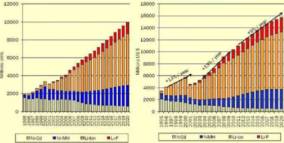
device tends to last longer than its battery. In Fig.1.1 we can see their alarming growth tendency
until 2020.
This massive battery production raises some grave issues, mainly the environmental
concerns regarding the hazardous substances that chemical batteries contain, increasing
difficulty in their disposal or and recycle, as these processes are quite delicate and costly, it was Fig. 1.1 Rechargeable battery market by chemistry (www.PrietoBattery.com
2 and still is mandatory to work out this issue and find a more conservative and sustainable
solution.
A new concept emerged over the last decades, this so called energy harvesting (EH), a
way to generate electrical energy from waste ambient energy with converters, to clarify, ambient
light, radio waves, temperature gradients, vibrations and other sources can be converted in to
electrical energy with solid state components, taking in account that this sources are relatively
weak, converters for EH have to be carefully design in order to have a high efficiency to yield
the maximum energy possible, making then viable.
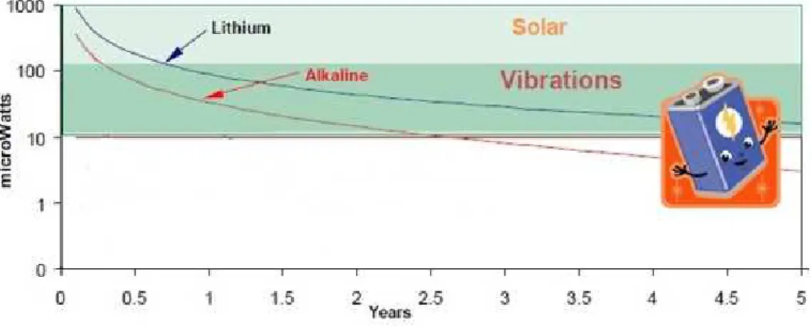
EH techniques are a great option for low power applications as life extending or even
replacement for batteries, as can be seen in fig.1.2. the amount of power that can be generated
by EH is low, in the milliwatt or microwatt range, but continuous, as long as the source intensity
is maintained, whereas batteries tend to deteriorate and lose the initial power offer, so
applications are limited but work well for low power applications that need to work much longer
than the life of a typical battery. This possibility of a promising future for sensors and other small
electronics, where the direct or indirect dependence of the power grid or constant replacement
of battery is eliminated, has attracted a lot of interest within both the academic and industrial
communities, in different areas of expertise.
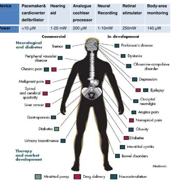
Medicine is one of the many areas where EH would fit in, using MEMS based EH would
be a great solution thanks to their size and also taking in consideration the low power demand
of medical electronics (ME), in Table 1.1 some examples can be seen. Each year more
3 Table 1.1 Examples of biomedical devices and their power demand
(www.Medtronic.com, 07/08/2013)
Device Pacemaker&
cardioverter
defibrillator
Hearing
aid
Analogue
cochlear
processor
Neural
Recording
Retinal
stimulator
Body-area
monitoring
Power <10 µW 1-20 mW 200 µW 1-10mW 250mW 140 µW
What better and closer source to supply ME than the own user, the HB is an amazing
example of a source of energy that is continuously being “lost” and within the wanted range of
energy, every second that we are alive our body is dissipating energy, in every step, in every
breath, in every heartbeat. The human muscles, by consuming chemical energy arising from the
food we eat, are able to make our body work creating mechanical energy and thermal energy,
this energy may be harvested by using and adequate transduction method. As we can see in
Fig.1.4 the most common source of energy of the HB and that has more available EH
techniques is the kinetic energy provided from human vibrations.
4 Fig. 1.4 Possible power harvested from the HB (adapted from Starner,1971)
Taking in account that human vibrations have an alternate input signal and that harvesters
require a continuous and steady output to create a stable power supply. For this to occur,
rectification has to be done using a AC-DC converter and voltage regulation using a DC-DC
converter to keep the output as constant as possible. This is one of the most important stages
of a EH device, where used devices have to be extremely efficient so their power consumption
is minimal. A storage unit may or may not be used, depending on the device requirements and
the source proprieties. If a bigger quantity of power is needed and if the device has no method
of handling it, a storage device such as an ultra-capacitor or a rechargeable battery will be
needed. Depending if it is a periodic need where a switch off mode could be used allowing
energy build up in ultra-capacitor and then used when the required amount is reached. Or if it is
more continuous need and the used source isn’t permanent or isn’t sufficient to sustain the
device, a battery will be necessary. In Fig.1.5 a schema of a self powered device is presented,
note this is a generic model, regardless the type of energy input so rectification may not be
5 Fig. 1.5 Self-powered device schema (M. Loreto,2009)
Imagine more and more low power wearable devices being totally independent from the
electrical grid and batteries thanks to EH from the human body, imagine leaving your house
without even thinking if you are going to run out of battery. This is the main motivation for this
thesis.
1.2 THESIS OBJECTIVES
In this thesis a study is performed about the energy that can be harvested from the HB and
its associated techniques. Taking into consideration the comparative study and the previous
work done by David Cavalheiro in his Breath Effort Transducer (BET) an EH prototype is
created and tested and its results are presented. Performed tests and experimental results are
original contributions.
1.3 THESIS STRUCTURE
This document describes the research and work developed and it organized as follows:
Chapter 1, in the Introduction the motivation, objectives and structure of the thesis are
presented to the reader.
Chapter 2, in the state of the art a study of the theory behind the EH is made. Achieved
values of other works are tabled and the most relevant ones are presented.
Chapter 3, in Prototype and its components the various components of Harvesting Device
are described.
Chapter 4, in Experimental procedures, the Biopack experiment procedure and the
prototype testing procedure are presented.
Chapter 5, in Experimental results and analysis, the Biopack experiment results and the
prototype testing results are presented and analysed.
7
2 State of the Art
The exponential growth of low power Personal Electrical Equipments (PEE) and their
battery dependence turned the HB into a very attractive power source. New and reliable
independent ways of power supplying PEE and other electrical devices have been research
over the last decades. Creating electric generators that feed unnoticeably on the renewable
energy created by the HB. Replacing or largely decreasing the use of batteries and the
dependence of electrical grids can be one of most important steps given by mankind in the
direction of a sustainable more nature friendly world in regards to PEE’s.
The research starts in section 2.1 by describing the various energies the HB produces and
the known techniques of harvesting them. Before the harvested energy can properly used to
supply any electrical device it was to be attuned to the required power input. In section 2.2
some conversion techniques are presented and then compared. In Section 2.3 a brief
discussion on whether the use or not of a storage unit.
2.1 HUMAN POWER AS A SOURCE OF ENERGY
The evolutionary process of the human race has developed the muscles, which basically
are the motors of the HB. Muscles convert chemical energy into mechanical energy with an
efficiency that rounds 25. In this process thermal energy is also produced. By doing so our
muscles keep us alive i.e., they make us move, pull oxygen into our system, pump blood into
veins and increase our body temperature. The muscles are the creators of all biomechanical
energy in the HB (Donelan,2009).
The idea of extracting energy from the HB is based on the fact that a person of 68Kg with
15% body fat, approximately stores chemical energy up to 384 MJ, and this stored energy in
average is consumed at the rate of 10,7 MJ per day equivalent to only 280g of body fat, having
a specific energy of 37kJ/g. Quantity of energy correspondent 800 AA batteries (2500 mAh),
that weight around 20KG, which is 70 times more. Which is almost the specific energy of crude
oil, 42kJ/g, is almost unbelievable the amount of energy that HB can store (Riemer,2009;
Starner,2004).
The HB can be seen as a reservoir of energy that never stops leaking, it in an active way or
in a passive way. Active when the action that generates energy is intentional and passive when
it is and unintentional. Energy that can be transformed in to electricity using the correct EH
method depending on the type of energy in question. In this warehouse one has three main
options as energy source: Chemical energy that can be found inside the HB in endogenous
substances that can be used as fuel for micro implantable fuel cells; Thermal energy that can be
harvest through thermoelectric generators using temperature gradients; Kinetic energy that is
8 three types of transducers: piezoelectric, electrostatic and inductive. These transducers can be
inertial and non-inertial (Tsai,2012).
2.1.1 Energy from within
There are substances within the HB that can be used as fuel for Micro-biofuel energy
harvesters (MBEH) to generate electrical energy through chemical reactions. Glucose is the
most common of these substances to be considered as the fuel for implantable fuel cells.
Through the oxidation of glucose, showed in Fig. 2.1, electrons are release, flowing from the
anode to the cathode creating an electrical current.
Few MBEH have been reported in the last years shown in Table 2.1 (adapted from
Tsai,2012). They are an amazing option to power implantable ME, due their continuous power
output and biocompatibility [4].
Table 2.1 Reported MBEHs (adapted from (Tsai, 2012)
Pdmax(µW/cm2) Material of electrodes Material of substrate Bio-fuel Y
26 Au PDMS/glass ABTS 2007
20.4 Carbon PDMS/glass Nafion/enzyme 2005
40 Carbon nano tube Si Glucose oxidade 2006
100 Polymer electrolyte N/A Glucose 2005
9
2.1.2 Energy from Heat
Taking in account that the conversion of energy in muscles is around 25% efficient, means
that most of the used energy is dissipated in form of heat, Table shows 2.2 the combined
energy and power dissipated in daily and biologic activities.
Table 2.2 Energy and power in selected activities (adapted from Starner,2004)
Activity Kilocal/hr Watts
Sleeping 70 81
Lying quietly 80 93
Sitting 100 116
Standing at ease 110 128
Conversation 110 128
Eating a meal 110 128
Strolling 140 163
Driving a car 140 163
Playing piano 140 163
Housekeeping 150 175
Carpentry 230 268
Hiking, 4mph 350 407
Swimming 500 582
Mountain climbing 600 698
Long-distance running 900 1048
Sprinting 1400 1630
Exhalation 0,34 0,4
Breathing band 0,36 0,42
Finger Motion 0,002 0,0021
Blood Pressure 0,32 0,37
Arm motion 0,28 0,33
Footfalls 7,13 8,3
Energy dissipated in this way may be scavenged using Thermoelectric energy harvesters
(TEH) that essentially are made of a thermocouple, a p-type semiconductor thermally
connected in parallel to a n-type semiconductor and connected electrically in series as showed
10 Fig. 2.2 TEH module (Loreto,2009)
These harvesters are based on the Seebeck effect, produced electrical current is
proportional to thermal gradient between the hot junction in contact with the HB and the cold
junction in contact with the environment. The Carnot efficiency sets an upper limit to maximum
recoverable power, assuming that the HB temperature is (310K, 37ºC) and the environment
(293K, 20ºC) (Starner,2004):
=
( )∗ 100% = 5.5%
(2.1)As the ambient temperature increases this value decreases. Considering a person that is
just standing at ease, a power of 128W is available checking the table 2.2, so using the Carnot
method to calculate the recoverable energy leads to a value of 7.04W at 20°C.
As closer as these temperatures are, the temperature gradient is smaller and the maximum
achievable power drops. Analysing the reaction of the human skin temperature regarding the
surrounding temperature seen in Fig. 2.2, the location of the TEH in the HB has to be carefully
chosen in order to maximize its power output (Leonov,2013).
Fig. 2.3 Human skin reaction to temperature (Tsai, 2012)
The maximum power produce by a TEH is given by:
=
!"#$11 Pmax being maximum power on electrically matched load, Z the thermoelectric figure of
merit, Z=S2σ/k, where S is the Seebeck coefficient, σ the electrical conductivity and k the
thermal conductivity, W the heat flow that passes the thermopile, W=∆T/Rtp, where ∆T is the
temperature difference in the thermopile and Rtp the thermal resistance at maximum power
(Leonov,2013).
In Table 2.3 we can see some TEH for the human body that were release in the last years.
Table 2.3 Reported TEHs
Pmax(µW) Material ∆∆∆∆T(ºC) Y/R
100a Poly-Si/Ge 12 2005/(Tsai,2012)
1-2a Poly-Si/Ge 10-15 2007/(Wang,2007)
9,22a Bi/Sb/Te/Se 5 2009/(Tsai,2012)
540 N/A 17 2013/(Leonov,2013)
500 N/A 17 2013/(Leonov,2013)
a
-MEMS based.
2.1.3 Energy from Movement
The most abundant and readily available source of energy in the HB is energy that comes
from movement. Each movement that we make, contracting our muscles, develop mechanical
power. Some examples are shown in Table 2.4 (adapted from Cavalheiro, 2011).
Table 2.4 Developed mechanical power in the HB
Movement Fingers Breath Blood flow Exhalation Arms Walking
Mechanical
Power(mW) 6,9-19,0 830 930 1000 3000 67000
The produced mechanical energy in the HB can be converted to electrical energy using
three type of transducers, that will analysed later in this thesis: inductive, electrostatic and
piezoelectric. There are two distinct methods of conversion using these transducers, the inertial
and the non-inertial method.
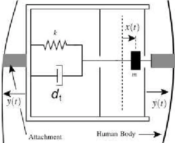
In the inertial method a Vibration Energy Harvester (VEH), Fig 2,4(adapted from
Mitcheson, 2010) is attached to the HB producing energy through the displacement or vibration
of a proof mass in spring-mass system, the energy obtained is directly reliant on the mass
value. The motion of the mass is described in equation (2.3), where x, y, dt, k, m represent
respectively the movement of the mass, the movement of the body, the total damping coefficient
regarding the sum of all damping done in the system, the elastic constant of the spring and the
mass (Cottone,2012).
12 Fig. 2.4 Model of a VEH attached to the HB (Mitcheson,2010)
Through the Laplace transform of the motion equation, the power dissipated by total
damping ratio is given in equation (2.4), where
ζ , 6
,7, 7
8 represent respectively the totaldamping ratio, the amplitude of the driving motion, angular frequency of the driving motion and
the natural frequency.
9:;;
=
<=>?"@AABCDC
E @AAB"F"GH <= @AABI"
(2.4)
In order to obtain maximum energy, these converters have to resonate at a particular
frequency, called the resonance frequency. This is the frequency of the mechanical input
source, in this case the human body motions, substituting
7 = 7
J and taking in account thatthe amplitude acceleration is,
K = 6 7
8 on equation (2.4), it yields the maximum powerdissipated.
9:;;
=
L?"
%MN<= (2.5)
Nevertheless, when MEMS base energy harvesters are used on microelectronic devices,
taking in consideration that
7
8= O1 '
⁄
, the resonance frequency increases due to thedecrease of the harvester size and mass and it becomes higher than the frequencies related to
the HB, where typical movement frequencies never pass 10Hz (Meng,2006).
The best way to max the power output of a motion-driven device is to increase the force
and the displacement of the given device. Conversely to inertial harvesters, non-inertial
harvesters have an external mechanical device that receives a force. In this case applied by the
HB see in Fig.2.5, for example around a muscle that when contracting its diameter changes
13 In the mechanical device the movement of the HB is turned into elastic energy or rotation
depending on the used device and through a converter is turned to electrical energy. Being
non-inertial, there is no proof mass so the power limit is no longer dictated by its limited inertia, but
by mechanical restrictions, the dimensions of the device and the input force through a
displacement, equation (2.6) (Mitcheson,2010).
Fig. 2.5 Model of a non-inertial harvester attached to the HB (Mitcheson,2010)
Q = R S. -(
?T
(2.6)
In equation 2.6, E is energy, f the applied force and x the displacement.
2.1.3.1 Mechanical energy conversion methods
When comparing all possible EH sources in the HB, the mechanical is the most potential
power source in the HB and the most accessible through adopting MEMS technology.
Mechanical energy can be converted into usable electrical energy through piezoelectric,
electromagnetic and electrostatic transducers. All of them can be used in mechanical energy
conversion, however each one can present specific advances depending on the given situation.
2.1.3.1.1 Electromagnetic conversion
Electromagnetic conversion is based on Faraday’s law, equation (2.7), which says that any
magnetic flux alteration in the surroundings of a closed conductor will induce a voltage, known
as e.m.f. (electromotive force), which is proportional to the strength of the magnetic field
variation. This is verified whether the field strength changes or the conductor moves through it,
U = −
9V9.(2.7) where -0 is the magnetic field flux variation over the surface of the electric conductor. In
electromagnetic harvesters, permanent magnets are usually used to produce the magnetic field
and coils as the conductors. This variation in the magnetic field strength can be generated by
14 rotating the coil relative to the magnet. For a coil moving through a perpendicular magnetic field,
the achievable voltage in open circuit is yielded by equation (2.8).
U
XT:Y= Z[\
99. (2.8) Where N, B, l and x are respectively the number of turns in the coil, B induction, the lengthof a turn in the coil given by 2^_ where r is the radius of the coil and the distance between the
magnet and the coil.
Normally, there are two types of electromagnetic vibration energy harvesters (EMVEH)
regarding the relative displacement, the movement between the magnet and the coil can be
lateral, Fig.(2.6) (a), or the magnet can move in and out of the coil, Fig.(2.6) (b) (Tan,2011).
Fig. 2.6 EMVEH models (Tan,2011)
EMVEH have high output current level but a low output voltage. External voltage source
isn’t required and there is no need for mechanical constraints. Taking in consideration that the
magnetic flux produced is yield by equation (2.9), more flux will be produced if wider area is
used, as result EMVEH rely largely on their size.
0 = R R [(`, *)-K
a(2.9)
2.1.3.1.2 Electrostatic conversion
Electrostatic conversion is based on variable capacitors. Inversely to normal capacitors,
one of the two electrodes sets of the variable capacitor moves, changing its capacitance
equation (2.10), due to the reducing of the overlap area or to the increase of the distance
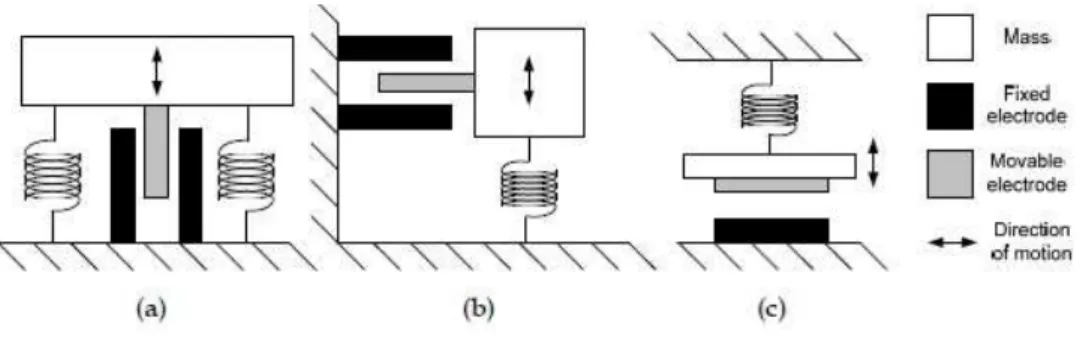
between the electrode plates. There are 3 typical types of electro static vibration energy
harvesters (ESVEH) shown in Fig. 2.7. There is the In-Plane Overlap which changes the
overlap area of the electrodes (a), the In-Plane Gap Closing which varies distance between
electrodes (b) and Out-of-Plane Gap which varies the gap between two larger electrodes (c)
(Tan,2011).
b = U
L9(2.10) where C is the capacitance, U the dielectric constant of the space or material between
15 Fig. 2.7 ESVEH models (Tan,2011)
When the capacitor is charged and its movable electrode is moved against the produced
electrical field, mechanical energy is converted to electrical energy. There are two different
techniques of employing electrostatic conversion, constant charge or constant voltage. If a
constant charge Q, is kept on the capacitor while is capacitance C, decreases, the voltage U will
increase, equation (2.11).
c ↑=
f ↓e (2.11) If a constant Voltage U, is maintained on capacitor while its capacitance C decreases, thecharge will decrease, equation (2.12)
h ↓= c ∙ b ↓
(2.12) These conversion techniques can be better explained by looking at the diagram in Fig. 2.8,
where the path ABDA refers to the constant charge technique and path ACDA to the constant
voltage technique.
16 In both techniques the variable capacitor is only to be charged when at its maximum
capacitance, that occurs in point A, for achieving maximum efficiency the precharge as to be
extremely synchronized with movement that triggers the variation of the capacitance. From A to
B in the constant charge technique or from A to C in the constant voltage technique the
capacitor is charged to a primary voltage, Ustart and Umax respectively, then as the electrode
plates take apart from B to D or from C to D, the capacitance decreases from Cmax to Cmin and
as the charge or the voltage is kept constant, the voltage increases or the charge decreases. In
both these processes mechanical energy is converted into electrical energy. In both cases the
path D to A represents the discharge of the capacitor. The main difference in the constant
voltage technique is that a larger initial voltage is needed and there is more net energy gained,
yielded by the area ACD and ABD in the constant charge, where the net energy is lower but
with also lower pre-charge (Tan,2011).
ESVEH have a high voltage output and low output current. They are easy to integrate with
MEMS technology, as the main components are variable capacitors, which are commonly used
in MEMS devices. However, mechanical constraints and external voltage source or pre-charged
electrodes are necessary.
2.1.3.1.3 Piezoelectric conversion
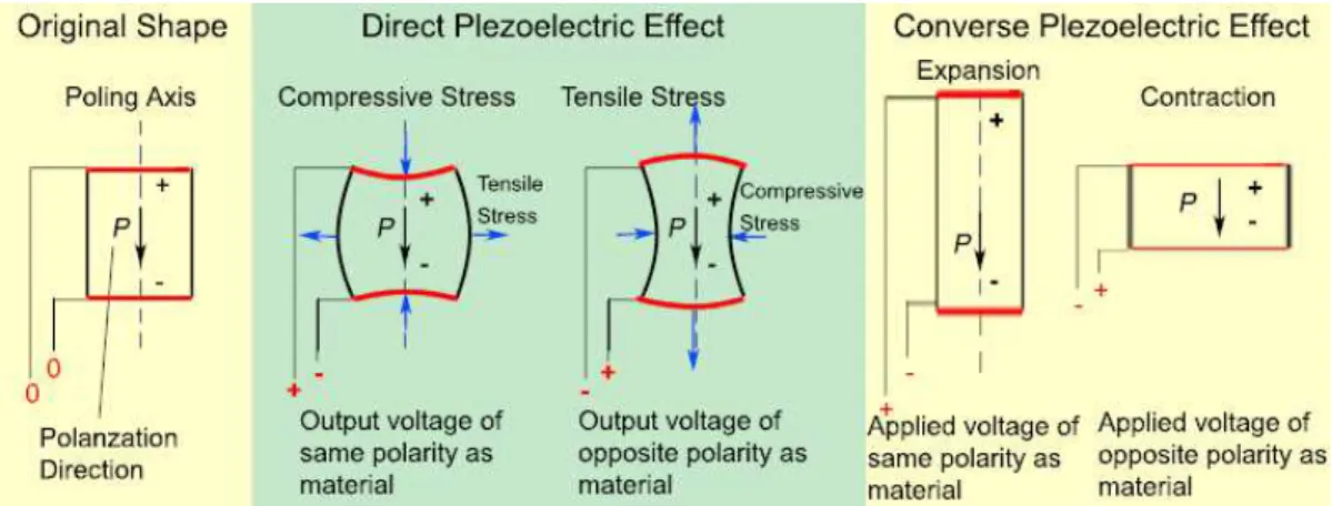
The Greek-Derived word piezoelectricity meaning ‘’pressure electricity’’ describes an
effect that was discovered in 1880 by the brothers Pierre and Jacques Curie. This effect called
the direct piezoelectric effect can generate electric charge through the application of mechanical
stress, and conversely, a mechanical deformation is generated when the ceramic is submitted
to an electrical field, as it can be seen in Fig.2.9. This effect occurs due to the separation of
electric charge in the crystal structure required to produce electric dipoles. (Tan,2011).
The Curie brothers noticed that piezoelectricity is observed only in crystals with no center
of symmetry because in noncrystalline materials and in the centrosymmetrical types of crystals Fig. 2.9 Piezoelectric effect
17 the charges tend to be displaced in opposite directions; therefore, pressure produces no
external electrical effect in them. Crystals of low symmetry, however, have a tendency for their
valence electrons to be squeezed in one direction polarizing them by doing so, furthermore, it
was also observed that piezoelectricity is an anisotropic characteristic, and when a piezoelectric
material is heated above his stated Curie temperature it tends to align its structure to a more
symmetrical one, losing its polarization, decreasing is piezoelectric performance Fig.2.10
(Mateu,2005).
Fig. 2.10 Temperature effect on a piezoelectric material
(http://resources.edb.gov.hk/physics/articleIE/smartmaterials/SmartMaterials_e. htm, accessed 03/04/2013)
The most used piezoelectric materials are the ceramics, due to the high dielectric
constant that results from its polarization process and due to its high resonance frequency.
In piezoelectric materials there is a strong electromechanical interaction that can be
translated in a simplified form by the equations 2.13 and 2.14.
j = -k + U Q
(2.13)
l = l
mk + -Q
(2.14)
Where D (C/m2) is the electric displacement, T (N/m2) is the applied mechanical stress, S
(m/m) is the mechanical strain, SE is the mechanical strain developed when a mechanical stress
is applied at a constant electric field, E (N/C) is the applied electric field, d (C/N) is the
piezoelectric charge constant that represents the dielectric displacement developed when a
mechanical stress is developed and
U
the dielectric permittivity of the material when submit toa constant mechanical stress.
The two more common ways of engaging a piezoelectric material into generating
electric charge are the 33 mode and the 31 mode, represented in Fig. 2.11, describing the three
18 Fig. 2.11 Piezoelectric generating modes (Cottone,2012)
The voltage (U) and the charge (q) obtained by each mode is shown in Table 2.5.
Where g (Vm/N) the piezoelectric voltage constant, is the electric field generated by a
piezoelectric material when mechanical stress is applied, the dimensions of the piezoelectric
material are given by W width, L length and H thickness, the applied force is given by F.
Table 2.5 Charge and voltage equations of piezoelectric modes (adapted from Mateu,2009)
Mode 31 Mode 33
U
n
o
p
n
pq r
o
q
-
o q
r
- o
The first subscript to d and g indicate the direction of polarization generated, the second
subscript shared by F subscript is the direction of the applied stress or the induced strain.
Piezoelectric converters compared with other converters have much higher voltage levels, don’t
need external voltage sources to start the process and have no mechanical limitations, however
they are more difficult to implement with MEMS technology, the smaller the device the less
charge is generated.
Fig. 2.12 Piezoelectric circuit model (Cottone,2012)
In Fig. 2.12 an example of a piezoelectric generator (PEG) circuit is presented. Formed by
19 Rp. The RL load is not part of the piezoelectric circuit, but is used to calculate the generated
power with equation (2.15).
=
st u"#v
(2.15)
2.1.3.2 Mechanical energy conversion methods comparison
In particular, when dealing with mechanical energy scavenging, many studies are
considered, by analysing each method advantages and disadvantages in Table 2.6 (adapted
from F.Cottone, 2012), a better awareness of the mechanical conversions methods can be
reach and conclusions can be taken.
Table 2.6 Conversion techniques comparison
Type Advantages Disadvantages
Electromagnetic -no need of smart material -no external voltage source
-bulky size: magnets plus coils
-difficult to integrate with MEMS
-max voltage of 0,1V
Electrostatic
-no need of smart material
-compatible with MEMS
-voltages of 2~10V
-external voltage source need
-mechanical constraints need
-capacitive
Piezoelectric
-no external voltage source
-high voltages of 2~10V
-compact configuration
-high coupling in single crystals
-depolarization
-brittleness
-charge leakage
-high output impedance
The more significant disadvantages are present by the electromagnetic and the
electrostatic methods, the bulky size and the need for external voltage source respectively. The
piezoelectric conversion method is considered the potential choice when compared with
electromagnetic and electrostatic conversion due to the high energy density that the
piezoelectric materials provide. Such comparison is given in table 2.7 (taken from Mickaël
Lallart, 2012).
Table 2.7 Energy density comparison
Type Energy Density (mJ cm-3)
Piezoelectric 35.4
Electromagnetic 24.8
20
2.1.3.3 Mechanical human EH developed projects
Many projects were developed on mechanical EH harvesting in the last decades, using
difference approaches and materials depending on the conversion technique and on the used
input source. In the next sections the used materials and some relevant projects on Human EH
using each conversion technique are described and analyse.
2.1.3.3.1 Piezoelectric developed projects and used material
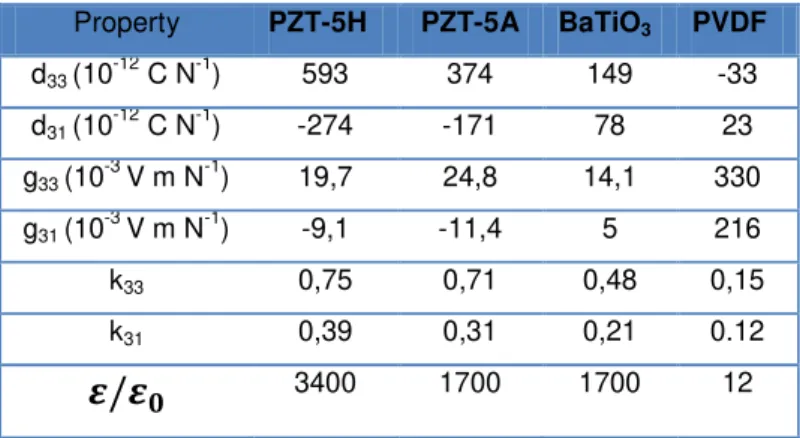
The most common man made materials used in piezoelectric EH and in others applications
such as sensors or actuators can be seen in Table 2.7 (Cottone, 2012). Barium titanate
(BaTiO3) was the first piezoelectric ceramic discovered, lead zirconate titanate
(Pb[ZrxTi1−x]O3) more commonly known as PZT, which is the most common piezoelectric
ceramic in use today and polyvinylidene fluoride (PVDF) that exhibits piezoelectricity several
times greater than quartz. Unlike ceramics, long- chain molecules attract and repel each other
when an electric field is applied. This table also shows relevant proprieties of these materials in
both horizontal and vertical directions and also includes their dielectric constant.
Table 2.7 Piezoelectric materials and either proprieties
Property PZT-5H PZT-5A BaTiO3 PVDF
d33 (10-12 C N-1) 593 374 149 -33
d31 (10 -12
C N-1) -274 -171 78 23
g33 (10 -3
V m N-1) 19,7 24,8 14,1 330
g31 (10-3 V m N-1) -9,1 -11,4 5 216
k33 0,75 0,71 0,48 0,15
k31 0,39 0,31 0,21 0.12
w/w
y 3400 1700 1700 12In Table 2.8, some recent piezoelectric human EH systems are shown and then analysed.
Table 2.8 Piezoelectric human EH systems
Source Frequency
(Hz)
Average Power
reported(mW) Ref
Heel strike 1 90,3 (Howells,2009)
Footstep 1 0,00034 (Klimiec,2008)
Walking (backpack) 2,75 0,4 (Feenstra,2008)
21 Fig. 2.12 The heel Strike System
The Heel Strike System (Howells,2009), is a system that converts mechanical strain into
electrical energy using the piezoelectric effect, it is divide in two parts, the Heel Strike Generator
that uses the body weight in each gait to apply stress in a lead screw and gear train, converting
that stress into rotation deflecting sinusoidally four PZT-5A(Lead Zirconate Titanate) bimorph
crystal stacks, each one out of phase 90º, so they absorb most of the elastic energy created this
way, generating electrical charge, then the second part of the system comes in to action, a
power electronics circuit that extracts, stores and regulates the electrical energy from the four
phases and converts them into a output 12VDC voltage pulse. There are three main issues in
this system, firstly the rotation is not entirely cancelled after each oscillation so the resulting
force opposes the down force created by the user in each step, reducing the mechanical energy
produce, lowering the conversion efficiency. Secondly is the locating of the system, most of the
low power devices that can be supply by such generator are at waste level or even higher,
rising the distance from the generator to the consuming device increases the energy lost in the
transport between them and it maybe be nuisance to the user, and thirdly obviously power is
only generated while walking, so whenever the user stops, the electrical energy production also
stops, this can be a problem depending on the purpose of this generator.
22 Most of the piezoelectric materials have high stiffness, making then hard to be implement
in human activities without being noticeable to the user. In (Klimiec,2008) a new type of
piezoelectric material is used, a extremely flexible piezoelectric polymer film is used in shoe
insole, weighting only 0,1012 g a single foil generated 340 nW. Applying multilayer foils would
easily increase the generated power significantly.
Fig. 2.14 Backpack energy harvester with mechanical amplification
As said before piezoelectric stacks have poor energy efficiency in harvesting applications
due to their high stiffness that makes the material very difficult to strain. In (Feenstra,2008)
another way is used to facilitate the straining process, using a mechanically amplified backpack
energy harvester which allows the relatively low forces generated during the human walking to
be transformed to high forces on the piezoelectric stack. The results show an increase of 12%
in power output over the previous backpack generators without mechanical amplification,
making it extremely relevant to consider the use of mechanical amplification in pressure based
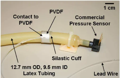
23 Fig. 2.15 Arterial Cuff Energy harvesterr
An implantable power source (Potkay,2008) that harvests energy from the movements
created flow of blood passing in the arteries. The 0.25 cm2EH device consists of a piezoelectric
film embedded within a flexible, self-curling medical-grade silicone cuff. It is expected to enable
self-powered implanted microsystems with increased lifetime, reduced surgical replacement,
and minimized external interface requirements compared to its current alternatives. The
fabricated device generates up to 16 nW when tested around a mock artery.
2.1.3.3.2 Electromagnetic developed projects and used materials
The most common magnetic material used in electromagnetic EH can be seen Table 2.9
(taken from www.IBSMagnet.com) with their most relevant properties. Being
Neodymium-Iron-Boron (NdFeB) of all the permanent magnets the most used, thanks to its high induction and
coercivity.
Table 2.9 Magnetic materials and properties
Property NdFeB Sm2Co17 SmCo5
B (mT) 262-278 159-175 143-159
Hc (kA/m) 860-915 636 620
Max operating temp
(ºC) 120 300 250
Density (g/cm3) 7,5 8,4 8,4
24 In Table 2.10, some recent electromagnetic human EH systems are shown and then
analysed.
Table 2.10 Electromagnetic human EH systems
Source Frequency
(Hz)
Average Power
reported(mW)
Ref
Foot motion 1,75 830 (Zeng,2011)
Wrist swing 1.4 to 2.8 0,00361 (Jia,2009)
Walking 2 0,3 0,952 (Saha,2008)
Slow running 2,75 1,86-2,46 (Goudar,2012)
Fig. 2.16 Unconventional electromagnetic energy harvester
One of the greatest prototypes ever made on harvesting the human foot motion is the
unconventional electromagnetic energy harvester seen in (Zeng,2011). Instead of using
conventionally a coil and a permanent magnet, it uses a translator (Fig. 2.16). That consists of
several horizontally magnets with soft magnetic spaces between them. The stator is composed
by several in line coils in both sides of the translator to maximize the power output. A spring is
connected to a fix platform to provide the sinusoidal movement. A rolling-element with low
friction coefficient is placed under the translator to provide a more fluid movement. No other
EMVEH researched in this thesis provides a better power output than this system. Using a
MPPT (Maximum power point tracking) algorithm regulated for low frequency of foot motion it
25 Fig. 2.17 The LMMG
The Liquid Metal Magnetohydrodynamics Generator (LMMG) (Jia,2009) comes with a new
concept of flexible energy conversion, adapted to the unpredictable nature of the human
movements such as the wrist swing for example. It consists on the electric potential produced
when a metal passes through a magnetic field and in this case liquid metal (Ga62In25Sn13), to
provide the desired flexibility to the converter, rectifying the flow of the material with a plastic
valve, but as the previous generators still triggered by an active source of the human body. If we
are standing still no power is generated.
Fig. 2.18 The magnetic spring generator
The magnetic spring generator (Saha,2008) uses the basic principle of electromagnetic
conversion to convert the vibration of the human body, using the magnetic field of a permanent
26 of using a single main magnet, two magnets are glued together separated by a soft pole to
increase the linkage flux and instead of a regular spring, a magnetic one is used to increase the
vibrations velocity of the main magnet, this magnetic spring is structured by a tube with one or
two fix magnets at its extremities, so when the main magnets reaches one of the extremities is
repelled to the other end, bouncing between them, or just increasing the speed in one direction
if only one fix magnet is used, decreasing the elastic constant but increasing the displacement.
The main difficulty faced by this harvester is that a resonant frequency will be hard to achieve
due to the low frequency and the lack of steadiness of human motion, and again depend of an
active source, once we stop moving the production comes down to zero.
2.1.3.3.3 Electrostatic developed projects and materials
The most common materials used in electrostatic EH are the Electroactive Polymers (EAP)
indicated in Table 2.11 with their most relevant properties. The dielectric elastomers (DE) of all
the EAP are the most promising material in human energy harvesting. It has an amazing
elasticity, matching perfectly human muscles and also a great energy density comparing to
other EAP. Comparing to Electrostrictive Polymers (EP) such as (P(VDF-TrFE-CFE) (vinylidene
fluoride trifluoroethylene chlorofluoroethylene polymer) to acrylic DE the energy density more
than 3 times lower. Regarding integrated electrostatic EH devices based on non EAP, they
normally use variable capacitors which are more suitable to machinery vibrations than to human
vibration.
Table 2.11 EAP properties (Kornbluh, 2004)
Property
DE EP
Polyaniline Polyelectrolyte acrylic silicone
(P(VDF-
TrFE-CFE)
Graft
elastomer
Max. strain (%) 380 63 4,5 4 10 >40
Max. pressure
(MPa) 8,2 3,0 45 24 450 0,3
Elastic energy
density(J/cm3) 3,4 0,75 1,0 0,48 23 0,06
Max efficiency(%) 60-80 90 n/a n/a <1% 30
Relative cycle
speed normal fast fast fast slow Slow
In Table 2.12, some recent Electrostatic human EH systems are shown and then further
27 Table 2.12 Electrostatic human EH systems
Source Frequency
(Hz)
Average Power
reported(mW)
Ref
Footstep 1 200 (Goudar,2012)
Knee rotation 1 0,15
(Jean-Mistral,2008)
Fig. 2.19 Dielectric elastomer system
DE are deformable polymer films that are built most commonly by acrylics and silicones
due to their high elasticity, electric permittivity that is 3 to 10 times greater than the air-gap in
electrostatic transducers. Comparing to piezoelectric elements they are much softer and their
operational boundaries change when strained, creating the possibility of extracting more energy
when stretched. Their high elastic energy density means that with the same quantity of material
more energy can be stored, being less obtrusive and more productive transducers, which is
very convenient when used in human EH. Being highly elastic materials and not using inertial
masses makes them highly efficient working at low frequencies, a characteristic of human
motion. In (Goudar,2012) a DE is placed in a shoe insole harvesting the pressure made in each
step, being barely noticeable by the user, having 5 times improvement over regular PEGs. The
main problem is that it is needs a 2,5 kV charge exactly applied when the pressure reaches is
max.
Fig. 2.20 Electrostatic backknee harvester
DE instead of being used under pressure can also be used under strain since their
straining ability reaches up to 400%. In (Jean-Mistral,2008) DE is placed in a mechanical
28 mechanical scavenger at the right of the picture. Everything the user takes a step it stretches
the DE an electrical charge is applied and as the leg comes back energy is generated. This
system is very interesting because it actually helps the walking movement. The main problem
as all the DE systems is the required high operation voltage.
2.2 CONVERSION TECHNIQUES
All kinds of mechanical energy harvesters, piezoelectric, electromagnetic and electrostatic,
are usually employed for the supply of low power electronic devices which require a continuous
and stable energy input. Granted that most systems based on the former types of mechanical
EH have alternate and unstable outputs, the need for regulation and rectification arises in order
to obtain a steady, single polarity voltage, allowing the supply of an electronic device. Such
method increases the usable power produced by the harvester.
2.2.1 Basic conversion technique
In order to collect the energy generated by the harvester, the standard approach is to
directly connect it to a full rectifying bridge, followed by a filtering capacitor, CR, smoothing and
stabilizing the tension oscillation, as shown in Fig.2.21.
Fig. 2.21 Basic conversion setup and associated waveforms (Inman,2009)
While there is a continuous voltage applied to the load R, the bridge rectifier is blocked
when the harvester’s voltage U is lower than the rectified voltage UDC in absolute value. The
voltage variation is proportional to the strain due to the current I, which exists the piezoelectric
elements at a null value. As soon as the voltage U reaches UDC, the bridge rectifier conducts,
preventing U from changing. Just as the absolute value of the input source u decreases, the
29
2.2.2 SSHI technique
The synchronized switch harvesting technique (SSHI) technique is similar to the simple
conversion technique earlier described with an added a switching system in parallel or in series
with the harvester elements. While Fig.2.21 shows the setup and the associated waveforms for
the SSHI parallel technique, Fig.2.22 presents the SSHI series technique.
Fig. 2.22 SSHI parallel stetup and associated waveforms (Inman,2009)
The IP current conducted through the bridge rectifier is null as long as the harvester’s
voltage U is lower than the rectified voltage UDC in absolute value. The voltage variation is
proportional to the displacement. As the absolute value of U equals UDC, the bridge rectifier
starts conducting, ceasing the evolution of U. When the displacement u decreases in absolute
value, i.e., when a maximum displacement is reached, the bridge rectifier ceases conducting,
coinciding with the beginning of the voltage inversion. By annulling the IP current absorbed by
the bridge rectifier leads to the release of the current Is in the inversion inductor.
Fig. 2.23 SSHI series stetup and associated waveforms (Inman,2009)
The voltage on the load resistor is continuous in the series SSHI technique configuration.
30 with an inversion conductor. The harvester current I is invariably null, the only exception being
during the voltage inversion phases. The technique assumes a perfect bridge rectifier as well as
a smoothing capacitor Cr large enough to render the voltage UDC constant. Throughout the
voltage inversion phases, the voltage at the bridge rectifier input equals +UDC and –UDC, when
the voltage switches to negative and positive, respectively.
2.2.3 SECE technique
This technique considers a device able to extract energy on the harvester elements within
a very brief period of time. Fig.2.23 presents the device applied in the implementation of the
Synchronous Electric Charge Extraction (SECE) technique and associated waveforms. In order
to bring back the voltage of the piezoelectric elements to zero, their electrostatic energy is
extracted at each maximum of displacement. UM represents the maximum voltage for a positive
alternation between instants t1 and t2.
Fig. 2.24 SECE series stetup and associated waveforms (Inman,2009)
The flyback architecture (Fig. 2.24) is one of the possible setups for a load extraction circuit
regarding the SECE technique. The voltage gate UG of the MOSFET (Metal Oxide
Semiconductor Field Effect Transistor) transistor T controls this kind of converter. This voltage is
determined by a control circuit which detects zeros and maximum peaks of the rectified voltage
UR. Upon reaching a maximum, a voltage of 15V is applied to the transistor gate, setting it to
on-state, allowing the transfer to inductance L energy of the harvester elements. As soon as the
electric charges presented in the electrodes have been extracted, the control circuit recognizes
the cancelation of rectified voltage UR, thus applying a null voltage to the transistor gate. This
operation blocks the transistor, places the harvester elements in open circuit and flows the
energy present in the coupled inductor L to the capacitor CR. The theoretical efficiency of the
ideal flyback converter is unitary. The output power therefore equals the input power of the
31 the DC-DC converter is uniquely determined by R. In practice, however, the efficiency of the
converter is inevitable imperfect and depends on the load resistance. The power at the
converter input is the same as the power extracted from the harvester elements.
Fig. 2.25 Flyback architecture of a SECE device (Inman,2009)
2.2.4 Comparison of the techniques
The comparison of the four techniques is made through observation of the evolution of the
harvested power as a function of the electromechanical figure of merit evolution of the
normalized harvested power in comparison to the maximum power harvested with the standard
circuit in Fig.2.25. The considered load is chosen to maximize the power supplied by energy
harvester in both cases. Depending on the losses of the circuits used for implementing each
technique, the series and parallel SSHI may prove better in practice.
Fig. 2.26 Comparison of the conversion techniques (Inman,2009)
The SECE technique presents itself the most efficient for a low electromechanical figure of
merit. Nevertheless, as it increases from approximately 1.4 to 2, the SSHI techniques proves to
perform with greater efficiency. After 2, the standard method proves to be the fittest. As so,
32
2.3 S
TORAGEU
NITThere are three possible scenarios of a storage unit in a EH system. First, when the
system fully matches the electronic device energy demand, a storage unit won’t be necessary.
Secondly if the system produces more energy than the device requires but isn’t always active,
then a battery would be the best choice, so the electronic device can remain active even when
the EH system isn’t producing energy. When it is producing energy in excess it will be stored in
the battery. Or thirdly if the device requires more energy than the EH system can provide but
just for brief moments, then a supercapacitor would be the best choice, when the device is
offline and the system is producing energy, it can be stored in the supercapacitor and used later
when a higher power demand is needed to activate the electronic device.
The main advantages and disadvantages supercapacitors have facing batteries are shown
in Table 2.13.
Table 2.13 Supercapacitors versus batteries
Advantages
Almost unlimited life cycles
Very fast charging
High power density
No heat release during discharge
No risk of overcharge, maintaining an permitted tension
Fast discharges don’t have any negative effects
Long life time
Good behaviour at high temperatures
Disadvantages
Low stored energy density compared to batteries
High natural discharge
Low max voltage
High voltage drop during discharge
When choosing a storage unit for an EH system is very important to first analyse and
compare the power source with the power demand of the device that is going to be supplied,
only after, a storage unit can be properly chosen. In cases where high power densities are
necessary for short intervals supercapacitors are the answer, due their high power density. In
situations where a constant voltage is needed for a longer period of time batteries will be the