Faculdade de Engenharia da Universidade do Porto
Development of an Argos Beacon for the VORSat
Satellite
Eduardo Moreira Coelho De Magalhães
D
RAFTV
ERSIONDissertation developed in the scope of the Integrated Master in Electrical and
Computers Engineering - Telecommunications Major
Supervisor:Prof. Dr. Sérgio Reis Cunha
January 2011
ii
iii
Abstract
As ESA (European Space Agency) is investing more in projects undertaken by young students from around the world, the opportunity arose to FEUP (Faculty of Engineering, University of Porto, Portugal), namely the VORSat team.
The project involves the construction of a cube-shaped satellite, whose aim is to prove the viability of the satellite attitude measurements from the Earth through multiple RF signals transmitted from orbit.
An important part of the project is the satellite reentry into the atmosphere. The VORSat team wishes to control the capsule trajectory that is going to be released from the satellite few orbits before its reentry into the atmosphere. The reason why is that VORSat team wants then to retrieve the satellite data stored by the capsule during the satellite orbit time. The idea is that through an Argos transmitter there may exist the possibility of communication between the capsule and the VORSat team ground station. The capsule would communicate directly and indirectly when necessary (through Argos satellites) with the ground station of VORSat team. The transmitter would serve as a beacon for the subsequent retrieval of the capsule once it splashes down into the ocean.
This thesis focuses on this part of the VORSat project. After studying the chosen system of communication, two programs were developed: a program to verify if the VORSat team is ready to receive and interpret messages sent by the Argos transmitter and another program to test Argos signal generation.
The obtained results were used to draw conclusions about the VORSat team difficulties and capacity to develop the Argos transmitter for the Cubesat capsule.
v
Resumo
À medida que a ESA (European Space Agency) investe cada vez mais em projectos realizados por jovens estudantes de todo o mundo, surgiu a oportunidade da FEUP (Faculdade de Engenharia da universidade do Porto, Portugal), nomeadamente a equipa VORSat, desenvolver o seu próprio projecto.
O projecto consiste na construção de um satélite em forma de cubo. O objectivo é provar a viabilidade das medidas de atitude do satélite, a partir da Terra, através de múltiplos sinais de rádio frequência transmitidos em órbita.
Uma parte importante do projecto é a reentrada do satélite na atmosfera onde é pretendido que a equipa VORSat controle a trajectória da cápsula que vai ser libertada do satélite, poucas orbitas antes de o satélite reentrar na atmosfera. Assim poder-se-á recolher a cápsula que contém os dados do satélite armazenados durante o seu tempo de orbita. A ideia é a de, através de um transmissor Argos, a cápsula comunicar directa e indirectamente, quando necessário, através de satélites Argos, com a estação terrestre da equipa VORSat. O transmissor vai servir de guia para a posterior recolha da cápsula, quando esta já tiver caído no oceano.
E é nessa parte que o trabalho realizado nesta tese incidiu. Depois de estudado o sistema escolhido de comunicação, foram desenvolvidos dois programas: um programa de descodificação para verificar se a equipa VORSat está pronta para receber e interpretar as mensagens Argos emitidas pelo transmissor Argos e outro programa para testar a geração de sinais Argos.
Os resultados obtidos foram usados para tirar conclusões acerca das dificuldades e capacidade da equipa VORSat para desenvolver o transmissor Argos para a cápsula do satélite.
vii
Acknowledgements
I would like to express my gratitude to my supervisor, Prof. Dr. Sérgio Reis Cunha, whose expertise, guidance, and support, were crucial throughout my thesis.
I must also acknowledge Eng. Mário Pereira and Eng. Sérgio Rui Silva for the transmitted knowledge in the early stage of my work.
A very special thanks goes out to my family and friends, specially to Frederico Moreira and my sister, Eng. Sara Magalhães, that without them I would not have completed my thesis.
ix
Index
Abstract...iii
Resumo...v
Acknowledgements...vii
Index...ix
List of Figures...xi
List of Tables...xiv
Abreviations and Symbols...xv
Chapter 1...17
Introduction...17
1.1 - Motivation...17
1.2 - Objectives...19
1.3 - Structure of the Thesis...19
Chapter 2...21
Literature Review...21
2.1 - Argos System Introduction...21
2.2 - Argos History...21
2.3 - Argos Enhancements...22
2.3.1 - Argos 3 - Signal Characteristics...23
2.3.2 - Argos 3 - User Platforms...23
2.3.3 - Argos 3 - Instrument...23
2.3.4 - Argos 3 - Two Way Communication Operating Mode...23
2.4 - Current Tracking Technology...25
2.4.1 - Argos...25
2.4.2 - Global Positioning System (GPS)...26
2.4.3 - Argos/GPS...27
2.4.4 - GPS Phone Tag...31
2.5 - Signal Processing...32
2.5.1 - Signal Reception and Treatment...32
2.5.2 - BPSK Modulation...32
2.5.3 - Argos Uplink Messages Structure...32
x
Chapter 3...35
Argos Uplink Signal Recepetion and Analysis...35
3.1 - Building the Antenna...35
3.2 - Receiving and Recording the Argos Uplink Signals...37
3.3 - Decoding Test...37
3.4 - Conclusions...44
Chapter 4...45
Development of the Decoding Program...45
4.1 - Decoding Program Structure...45
4.1.1 - Baseline Considerations...46
4.1.2 - Decoding Steps...48
4.2 - Results...50
4.3 - Conclusions...50
Chapter 5...51
Argos Signals Generation Test...51
5.1 - Argos Signals Generator Program...51
5.1.1 - Considerations...51
5.2 - Results...52
5.2 - Conclusions...57
Chapter 6...59
Conclusions and Future Work... 59
6.1 - Conclusions... 59
6.2 - Future work...59
xi
List of figures
Figure 1.1 – VORSat cube satellite...18
Figure 1.2 - Satellite capsule...18
Figure 2.1 - Principle of Doppler effect...26
Figure 2.2 - Argos PMT connected to a GPS receiver...27
Figure 2.3 - Argos transmitter on a peregrine on falcon...29
Figure 2.4 - Argos transmitters...29
Figure 2.5 - Temperature transmitting tag (SPOT)...30
Figure 2.6 - Argos/GPS tagged buoys...30
Figure 2.7 - Fastloc - GPS tag...30
Figure 2.8 - Argos/GPS tag on an elephant seal...30
Figure 2.9 - Argos pop-up tag...31
Figure 2.10 - GPS phone tag...31
Figure 3.1 - 401.65 MHz built antenna, not in proportion...36
Figure 3.2 - Built antenna installed in the ground station roof...36
Figure 3.3 - Receiver and computer used to record the Argos signals in the ground station...37
Figure 3.4 - Received signal plotted against background noise...38
Figure 3.5 - Zoom on the signal...38
Figure 3.6 - Fourier transform of the audio signal received from the USB radio ...39
Figure 3.7 - Zoom on the frequency difference applied in the signal fc...40
xii
Figure 3.9 - Lowpass filter planning...41
Figure 3.10 - Lowpass filter design...42
Figure 3.11 - Angle function of the filtered signal...43
Figure 3.12 - Zoom on the signal bit transitions...43
Figure 4.1 - Angle function of a received signal...47
Figure 4.2 - Differential of the angle function of the same signal...47
Figure 4.3 - Comparison between a non-filtered and a filtered signal...49
Figure 5.1 – Computer and signal generator used in the signals emitting...52
Figure 5.2 - Emitted signal...53
Figure 5.3 – Differential of the angle function of the emitted signal, as received in the vicinity...54
Figure 5.4 – Zoom on the differential of the angle function of the emitted signal, as received in the vicinity...54
Figure 5.5 - Received signal...55
Figure 5.6 - Differential of the angle function of the received signal...56
Figure 5.7 – Zoom on the differential of the angle function of the received signal...56
Figure 6.1 – Discrete circuit...60
xiv
List of tables
Table 2.1 - Evolution of Argos instrument capabilities...25 Table 2.2 - Location error classes...28 Table 2.3 - Argos uplink message structures...33
xv
Abbreviations and Symbols
List of abbreviations (sorted alphabetically)
RF Radio Frequency
BPSK Binary Phase Shift Keying CAD Computer Aided Design
CNES Centre National d`Études Spatiales CSA Over-sample Coefficient
CSL Collecte Localisation Satellites DBCP Data Buoy Cooperation Panel
DEEC Electrical and Computers Engineering Department DEM Digital Elevation Model
DFT Discrete Fourier Transform
DMMC Downlink Messaging Management Center ESA European Space Agency
FEUP Faculty of Engineering of University of Porto GPS Global Positioning System
IOC International Ocean Commission ISRO Indian Space Research Organization
JCOMMOPS Joint Commission for Oceanography and Marine Meteorology Observing Platform Support Center
NASA National Aeronautics and Space Administration NASDA National Space Development Agency
NOAA National Oceanic and Atmospheric Administration PMTs Platform Messaging Transceivers
POES Polar-Orbiting Environmental Satellites PSK Phase Shift Keying
RPU Receiver Processor Unit
SOOP Network of drifters and moored buoys Ship of Opportunity Program SWR Standing Wave Ratio
xvi
TBD Power Generation Mechanism
TXU Transmitter Unit
UATME Description of an acronomous as such as extense that eventually obliges the change of line
USB Upper Sideband
VNA Vector Network Analyzer
List of symbols
fc Carrier frequency
Biphase_L Biphase_L Encoding
17
Chapter 1
Introduction
This Thesis was developed within the subject “Dissertation 2010/2011” of Master‟s degree in Electrical Engineering and Computers and is incorporated in the project VORSat.
In this chapter, a contextualization of the dissertation is presented, relating this thesis with the VORSat project. Next, the objective of the thesis will be presented and finally the structure of the document will be detailed.
1.1 - Motivation
ESA (European Space Agency) has challenged the University of Porto to develop a CubeSat which is a very small satellite to be launched into a Low Earth Orbit (LEO).The name of this project is VORSat and its mission is divided into three parts [1]:
Attitude determination from the ground – the aim is to prove the feasibility of
satellite attitude measurements from the ground, based on multiple RF signals transmitted from orbit. The idea is to combine multiple signals and antennas so that certain information will depend on the direction of the modulated signal reception. This information is encoded in the form of signal phases, allowing determination of the attitude of the satellite with an expected degree of accuracy.
Controlled de-orbiting – adjust the drag coefficient regardless of the satellite
attitude using a control loop with feedback from GPS (Global Positioning System). Re-entry – one interesting point of this project is the fact that, for the first time,
there is the intention of manually retrieve, data that has been obtained and stored by the satellite, during its time of orbit, after its disintegration when crossing the atmosphere. The idea is to build a capsule that will be separated from the satellite interior, just few orbits before the satellite crosses the atmosphere above the United Kingdom or the North of Africa and then eventually will falls into the Atlantic Ocean near Portugal.
Inside this capsule, specifically designed to be able to cross the atmosphere, there will be an autonomic system prepared for the marine environment and capable of storing data (when inside the satellite and till the crash in the ocean)
18 Introduction
18
and transmit its coordinates so the VORSat team can manually retrieve the capsule and obtain the stored data.
Therefore, the capsule shall have a flash memory to store the data, an oscillation damping system, a system capable of transmitting the capsule coordinates, directly or through satellite communication, to the VORSat team ground station located at FEUP (Faculty of Engineering of Porto University) and a power generation mechanism (TBD) that will allow the capsule to transmit when convenient (given the need to save battery power).
Figure 1.1 – VORSat cube satellite [1].
19 Objectives
19
This thesis focuses on the transmitting system issue, where it details the first approach to solve the question through the development of an Argos transmitter that makes the transmission of the GPS coordinates of the capsule in the format of an Argos message possible.
1.2 - Objectives
The objective of this work was to initiate the study and project that will assure in the near future the communication between the satellite capsule and the ground station of the VORSat team. More specifically, to prove that the VORSat team is able by its own means to receive Argos uplink messages, decode them and that can build a simple (electronics and firmware) Argos transmitter. Such study consists in the development of software programs that can decode and generate Argos messages, resorting to radio receivers and RF signal generators/modulators.
Being able to decode the Argos messages without the CSL(Collecte Localisation Satellites) assistance is crucial. The reason why is that the VORSat team intends to control the capsule at vital points of its trajectory. To do so, VORSat team wants to establish simple tracking stations in points of interest, namely in the United Kingdom, the North of Africa and Portugal. It is expected that the capsule reentry into the atmosphere happens above the U.K or the North of Africa, so establishing a tracking station there on a suitable location would make the establishment of direct communication between the capsule and the tracking station possible. That way it would be possible to confirm its separation from the satellite few orbits before the satellite reentry into the atmosphere and track its trajectory till its reentry into the atmosphere. The other tracking station would be at FEUP ground station where, when the distance between ground station and the capsule during the fall is close enough to exist radio coverage, it would be possible to point an antenna directly to the capsule position and communicate with it.
Only when the capsule is already drifting on the ocean, it will be necessary to communicate indirectly through Argos satellites due to coverage problems.
To note that the Argos transmitter is meant to fit in the small capsule so it has to be a small scale transmitter supporting only the vital functions needed for the success of VORSat project, such as GPS location and basic telemetry information.
1.3 - Structure of the Thesis
This thesis is organized in six chapters. The first chapter consists in the thesis motivation, objectives to achieve and in the thesis structure. In the second chapter, a literature review is presented on various subjects and technologies relevant to this work. In chapter 3, all the Argos signals reception process are detailed from the building of the antenna, the reception of the signals by the ground station to the Argos signal interpretation analyses. In chapter 4 and 5 the development of the Argos decoding program and the Argos generator program, respectively, are demonstrated. In the final chapter the conclusions of the thesis and the future work are commented.
20 Introduction
21 Objectives
21
Chapter 2
Literature Review
2.1 - Argos System Introduction
Argos is a unique system of tracking and data collection that covers the whole world, dedicated to studying and protecting the environment by satellite communication. Since 1978, Argos responded to the needs of scientific and industrial communities in the world. Argos gives scientists a tool to enhance our understanding of our environment and help the industry to follow the regulations of environmental protection. Today, about 16,000 Argos transmitters are active each month worldwide [2; 3].
Applications of the Argos system include:
Locating buoys, fishing vessels, wildlife and any mobile platform carrying an Argos transmitter;
Collecting environmental data, from ocean temperature profiles to river levels or animal heart rates;
Observing the oceans and measuring currents, temperature and salinity; Monitoring public health, managing fisheries, enforcing maritime security.
2.2 – Argos History
In 1978, three major entities worked together to develop the Argos system: CNES (French Space Agency); NASA (National Aeronautics and Space Administration) e NOAA (National Oceanic and Atmospheric Administration), originally in order to collect and relay meteorological and oceanographic data all over the world. Later in 1986, CLS was created by CNES to operate and commercialize the Argos system.
At the present time, Argos system can count with several other international space agencies participation as NASDA (National space development agency) and Eumesat (European Organization of the Exploitation of Meteorological Satellites). Furthermore, negotiations have been made with ISRO (Indian Space Research Organization) in order to embark an Argos instrument on the Indian platform in 2011 [2; 3].
22 Literature Review
22
Therefore, Argos system is the main transmission channel and processing chain for data gathered by the following major international ocean observation programs: DBCP (Data Buoy Cooperation Panel); SOOP (Network of drifters and moored buoys Ship of Opportunity Program) and Expendable Bathythermograph lines Argo profiling float project supervised by the World Meteorological Organization and IOC of UNESCO (International Ocean Commission). All the data collected by these programs is used for several purposes like: marine safety; climate and weather forecasting; fishery management; maritime transport and offshore industry and defense. [3].
They are coordinated by JCOMMOPS (Joint Commission for Oceanography and Marine Meteorology Observing Platform Support Centre), that provides guidance and support to programs that use Argos‟s worldwide coverage to relay ocean observations and operates out of CLS‟s headquarters in Toulouse, near where collected data is processed and disseminated. [3].
2.3 - Argos Enhancements
Throughout the time the Argos system has been evolving, suffering constant enhancement features. To mark those enhancements, numbers are given to the Argos system refereeing the different and new stages of enhancements. At present time, Argos-4 is already being tested but as it is still a newly project the Argos-3 system that is being used for the past few years with high success will be detailed.[4]
Argos – 3 instruments brought several improvements to the performance of Argos system such as [3]:
Two-way communication with platforms – A new generations of Argos platforms
– the platform Messaging Transceivers (PMTs), provides the capability of uplink – downlink communication. DMMC (Downlink Messaging Management Center) is on charge of all downlink communication management, operated by CLS for CNES in Toulouse, France.
Greater volume of data transmitted during each satellite pass - with a high
speed of 4.8kbit/s uplink, it allows a ten times more data to be transferred per satellite pass than Argos-2.
More efficient data transfer – Instead of needing redundant messages to ensure a
high probability of data being received by satellites error-free, Argos 3 doesn‟t need any redundant messages since the Argos 3 instrument can send an “acknowledgement” signal to the PMT once data has been received error-free. Once the PMT receives the “acknowledgement”, it stops sending the message. Furthermore, since the PMT are equipped with satellite pass forecasting software, they can predict the exact time and duration of the next satellite pass, thanks to information communicated via downlink. Therefore PMTs only transmit when a satellite is in range, reducing transmission time, conserving energy and extending platform lifetime.
Platform remote control and programming – Now, users have the possibility to
send short messages to their platforms via the DMMC (up to 128 bits) and programming them remotely. Examples of typical applications of those messages
23 Argos Enhancements
23
are: switching a transmitter on/off; changing time or date configurations; modify a sampling rate of a sensor, etc.
2.3.1 – Argos 3 - Signal Characteristics
The transmission frequency of the Argos-3 signals is 401.65 MHz for uplink communications and 465.98 MHz for downlink communications and the variable repetition period is defined exclusively by CLS according to the application in use [3].
It is worth mentioning that since the Argos location calculation is based on measurements of the Doppler Effect on the signal, the frequency generator of to each transmitter within this range must remain stable. [3].
2.3.2 - Argos 3 - User Platforms
Despite the fact that all existing and future Argos-3 instruments are fully compatible with the current transmitters, it is although necessary the use of a Platform Messaging Transceiver (PMT) so users can benefit from the downlink communication technology and high data rate uplink unique to Argos-3. A PMT is capable of sending and receiving messages to/from satellite, as well as processing commands. Users equipped with a PMT and subscribed to the downlink service will fully benefit from the new communication capabilities made possible with Argos-3 [3; 5].
The first PMT prototypes were developed for the ADEOS-II satellite, a Japanese satellite (JAXA) launched in 2002 and ever since they have been getting reduced in size and enhanced in data volume from 1G-PMT to 2G-PMT( first and second generation of PMTs ).[2; 3; 5].
2.3.3 - Argos 3 – Instrument
Argos 3 instrument is divided into two parts [3]:
Receiver Processor Unit (RPU) – The RPU mission is to process the uplink signals,
measure the incoming frequency, time-tag the message, create and buffer mission telemetry, manage the downlink communication and provide an interface between the receiver, the TXU (transmitter unit) and the satellite. With fully digital processing, the RPU stores messages and either relays them in real-time to the nearest antenna or in deferred time to a global center. In case of malfunctioning a backup RPU is used.
Transmitter Unit (TXU) – TXU is responsible for sending signals to the PMTs,
including error-free messages acknowledgement signals. Through downlink communication, users will also be able to send defined PMT instructions (TXU can selectively address one or more PMTs) and system operators to send global messages/ commands such as satellite ephemeris or broadcasting time. A backup TXU is also included.
2.3.4 Argos 3 – Two Way Communication Operating Mode
Transmitters can be programmed to send messages to satellites at periodic intervals, transmitting only when a satellite is in range. Each message lasts 360 to 920 ms and includes
24 Literature Review
24
a preliminary synchronization sequence; a statement of message length; a transmitter ID number; a sensor/user data (512 to 4608 bits for Argos-3) and a checksum [3].
Argos-3 instruments fly on board the MetOp satellites launched in 2006 and 2010 (one more is planned for 2014) of the European Organization for the Exploitation of the Meteorological satellites (Eumetsat) and on board the NOAA N‟ that was launched in 2009. All these satellites are Polar-Orbiting Environmental Satellites (POES) that fly on a synchronous orbit, at 850 km altitude, picking up beacons and transmitters signals, storing them on-board, and relaying them in real time back to Earth.[3].
Both MetOp and NOAA satellites orbital revolutions transect the equatorial plane at fixed local solar times. Therefore, each satellite is in view of any given transmitter/beacon, basically at the same local time every day. At any given time, each satellite simultaneously “sees” all transmitters within an approximate 5,000 km diameter “footprint”, or visibility circle. The visibility circle sweeps around the Earth as the satellite proceeds in orbit. When a satellite equipped with an Argos instrument detects a transmitter, it receives the messages that the transmitter is sending (capable of receiving messages from over 1,000 Argos beacons transmitting simultaneously within the satellite‟s field of view). Then with the new feature of downlink communication, available in Argos-3 system, the satellite is able to send a signal back to the platform when a message has been correctly received. Furthermore, users can send messages to their platforms through the satellites [3].
The bridge between the satellites and the processing centres, is made by a L-band network of nearly 60 antennas located all over the globe to obtain worldwide coverage, that collect data from the satellites in real-time and relay the data to the processing centres.
There are two global Argos processing centres. One located just outside of Toulouse in Southwestern France and the other one near Washington, DC, USA. Once the data arrive at a processing center, locations are automatically calculated, all data are processed, and information is made available to users [3].
Argos users can choose how they wish to receive the data from the processing centres, it can be directly in their office, by email, fax, web, CD-rom or even on mapping software.
Argos users can also send messages via a web interface through the DMMC that relays messages to master platforms, located in Toulouse, Fairbanks and Svalbard. These master platforms are capable of communicating with the Argos-3 instruments aboard satellites.
When the satellite recognizes its target platform, (platform to which the message is addressed, Identified by its ID number), it sends the message, via the downlink, to the PMT. The satellite also sends system information via the downlink on the pass (system information includes time and orbit information, allowing the PMT to calculate the next satellite pass).
Upon receiving the message, the PMT sends an acknowledgement signal to confirm that the received message has no errors; then processes the command contained in it. It uses system information to calculate the next satellite pass, and then waits for the next satellite pass in energy-saving mode. [3].
25 Argos Enhancements
25
Table 2.1 - Evolution of Argos instrument capabilities [3].
2.4 - Current Tracking Technology
2.4.1 Argos
Argos system is being dominantly used for animal tracking from its beginning, particularly for species that travel considerable distances, or through inaccessible habits, whether in marine or terrestrial environments. The method of localization is the principle of Doppler Effect in which each time the satellite instrument receives a message from a transmitter, it measures the frequency and time-tags the arrival. The Argos processing centres compute the range of possible positions for the transmitter. It consists in a cone defined by a vertex at the position of the satellite when it received the message and the respective vertex angle, a function of the difference between the frequency measured on board the satellite and the transmitter frequency. With four or more messages received by the satellite, the location calculation process can begin, and an initial estimate of the platform is computed from the first and last messages collected during a single satellite pass and the last computed frequency of the transmitter. The intersection of the cones for these two messages with the terrestrial radius plus the height declared for the transmitter (altitude sphere) provides two possible locations and for each of the two possible locations, a least-squares analysis is used to improve the estimates of the transmitter's position and transmit frequency. However, if this analysis fails, the location process is not possible.[6; 7].
Then the location with minor residual error is chosen and tested for its plausibility. There are four plausibility tests: minimum residual error; transmission frequency continuity; minimum displacement and plausibility of velocity between locations. Unless the
26 Literature Review
26
users subscribe to Service Plus/Auxiliary Location Processing, in order to a location be validated and can be distributed to users, two of this test must be positive.
Also a digital elevation model (DEM), is used to reduce the altitude sensitivity risk of jeopardizing the feasibility of the locations accuracy [6; 7].
Figure 2.1 - Principle of Doppler Effect [7]-
The main issue of the Argos transmitting system by Doppler Effect is its limited accuracy on the achieved locations. It faces serious problems when speaking of air breathing marine vertebrates that spend much of their time submerged or drifting buoys that also face periods of submersion and therefore often obscured from overhead satellites, and also for terrestrial species that live in dense regions [6; 7].
To compensate its low number of good-quality locations the system delivers global coverage and the benefit of not having to recapture the study animals or retrieve the drifting buoys [6; 16].
2.4.2 - Global Positioning System (GPS)
Another tracking system that is also used is the GPS system, which provides high-quality location accuracy. The principle of this system is a constellation of earth-orbit satellites that in a continuing way transmit to the GPS receivers all the location and time information (ephemeris and almanac data) they need to calculate their location and elevation in real-time typically in order of 100 meters or less, or can store information on detected GPS signals, which are later processed into estimates of location.[8; 9].
The great drawback is the need to retrieve by removal the data tracking unit with GPS geolocation of the animal/buoy or by recovery of a self-release collar/harness bearing the tag. [8; 9; 16].
27 Current Tracking Technology
27
2.4.3 - Argos/GPS
At the present time, efforts are made to combine the two technologies, so it can be possible to cease their advantages and counter their disadvantages. Namely, the objective is to have the high-quality location accuracy of the GPS technology and the data-relay capabilities of the Argos system. This Argos-GPS system consists in a device that contains an Argos PMT connected to a GPS receiver where the GPS fixes collected at pre-set intervals will be coded in Argos messages and relayed to the Argos processing centres. Several fixes can be stored in a single Argos message; the total number depends on the coding and the required accuracy (up to a few meters for full GPS accuracy) [9; 10].
GPS fixes can be decoded, validated and distributed just like Argos locations and Argos Doppler derived locations can still be used as a back-up in case GPS signals cannot be received by the platform [9; 10].
Figure 2.2 – Argos PMT connected to a GPS receiver [7].-
Using GPS in addition to Doppler locations brings several advantages like more accurate and independent positions and the more regularly collection of positions over the day. However, there are some problematic issues on the use of this system. Dense vegetation, weather condition, altitude and antenna position can interfere with the quality of GPS communications and subsequently the transmission and/or reception of messages at satellites prepared with Argos instruments. Yet there is an even worse problem with the tracking of marine vertebrates, namely for the traditional GPS receivers as they typically require from 30 seconds to several minutes to obtain a satellite lock and location upon being switched or obtaining a clear view at the sky. With few surface time, wave wash, submersion and inappropriate antenna orientation, traditional GPS receivers have many difficulties in maintaining the signal lock. Therefore, ephemeris data cannot be downloaded and thus collecting location information becomes impossible [9; 10].
28 Literature Review
28
In response, some countermeasures have been created like Fastloc (Wildtrack Telemetry Systems Ltd, Leeds, U.K.) and TrackTag (NAVSYS Ltd, Edinburgh, U.K.) GPS receivers which are peripherals for integration into telemetry or archival wildlife-tracking hardware [6; 11; 12].
This equipment has been designed specifically to cope with the handicaps that traditional GPS receivers face, namely, the need to download almanac and ephemeris data to determine position accurately when an unimpeded view of the sky is sporadic and ephemeral. These GPS receivers are able to record the presence of signals transmitted by GPS satellites, within milliseconds, and do not need to download ephemeris information carried in the GPS signal. The received GPS signals data is then stored into the device and can be transmitted in Argos format messages (Fastloc GPS receivers) or archived onboard the device (TrackTag) for later retrieval, so in the end it is ready to derive likely positions [6; 11; 12].
Fastloc-GPS technology is more suitable for tracking animals where site fidelity to attachment regions is not well known and the chance of retrieval of equipment is low.
The derived Argos locations are classified according to following criteria: tracking system (Argos or GPS); estimated error and number of messages received during the pass of the satellite [6; 11; 12].
For each location an estimated error is calculated. The error is assumed to be isotropic and hence characterized by a single number called the radius of error. It corresponds to the sigma of the estimated location error and it is used to categorize the location class.
However, the location error cannot be seen strictly as an isotropic one, in fact, it is better approximated by an ellipse than by a circle. In order to deal with that, if the users desire to obtain a better portrayal of the location error, it is now possible for them to use provided data by CLS that corresponds to the ellipse of error locations [7; 13; 14; 15].
29 Current Tracking Technology
29
A good example of an Argos-GPS application is documented in the work undertook by David W. Sims et al (2009) [16]. In this experiment, three ocean sunfish Mola mola were captured in a tuna pound net off southern of Portugal, and tagged with a Fastloc GPS receiver and an Argos platform terminal transmitter, with the objective of determining and measuring the movements of these individual free-ranging animals. The Argos-GPS system was built inside a cylindrical capsule with a wrap-around buoyant collar and a hydrodynamic cone to reduce drag (height – 150 mm, float width – 80 mm; Argos antenna length – 171 mm).
This species usually dives at least 472 m of depth and can remain at deep depths for long periods of time, occasionally returning to the surface, so a saltwater switch was located near the Argos antenna to conserve the battery power for the submerged tag periods, and when at surface the Fastloc receiver was set to acquire the GPS position every 45 s and consequently the Argos transmission of messages containing the encoded GPS data every 60 s.
This work sustained the fact that GPS messages in Argos format tracking system is more accurate than the Argos Doppler effect method. Two series of locations were retrieved remotely from tags towed by sunfish and the one obtained through Fastlock GPS had better results than the one with Argos Doppler Effect.
Namely, with the Argos Doppler Effect method, the location accuracy results were: service providers, 150 m (location class 3) to 1000 m (location class 0); field tests (mean ± SD), 482 m ± 153 (location class 3) to 5179 m ± 3677 (location 0).
The second time series was calculated from remotely retrieved GPS data decoded from Argos messages by post-processing. The reported field-test spatial errors (mean ± S.D.) were: 8 satellites, 26 m ±19.2; 5 satellites, 64 m ±79.4.
Comparing the values of the two different methods, it is acknowledged the better accuracy of the Argos-GPS tracking system.
These are some examples of Argos and Argos-GPS transmitters:
30 Literature Review
30
Figure 2.5 – Temperature transmitting tag (SPOT) [18].
Figure 2.6 – Argos/GPS tagged buoys [19].
31 Current Tracking Technology
31 Figure 2.9 – Argos pop-up tag [21].
2.4.4 - GPS Phone Tag
Another plausible alternative is the GPS Phone tag technology that combines GPS quality locations with efficient data transfer using the international GSM mobile phone network [22].
Also using Fastloc GPS receivers to acquire fast information needed to determine a location, the main feature of this technology is the fact that data is relayed via quad-band GSM mobile phone module when the animal is within GSM coverage, which allows for a high bandwidth, low cost and high energy efficient system [22].
When within GSM coverage, the entire set of data records stored in memory can be relayed via the GSM mobile phone system. Data can also be stored for up to six months on-board the tag so it can be downloaded when the tag is retrieved [22].
32 Literature Review
32
2.5 - Signal Processing
2.5.1 - Signal Reception and Treatment
In the present Argos system, the satellite transponders receive the signals from the Argos transmitters, with noise, in the UHF [2] 401.65 MHz ± 30 kHz frequency band and translate them to the band between 65 to 125 kHz. Before transmitting to the terrestrial stations of reception this band modules in phase a carrier in band S of 2.267 GHz and then the reception stations demodulate the signal recovering the 65 to 125 KHz band signals. After that the processing centres detect and demodulate the signals which results in BPSK signals format that at last have to be demodulated again [23].
2.5.2 - BPSK Modulation
The type of modulation used in the transmitting process of Argos system is phase shift keying (PSK modulation).
It is a subtype of phase modulation which is in turn a subtype of angular modulation. In angular modulation the carrier angle is changed linearly with the message signal (baseband).
Assuming that θc(t) indicates the angle of a sinusoidal modulated carrier which is supposed to be a function of the message signal, the resulting angular modulated wave is expressed by:
)]
(
cos[
)
(
t
AC
c
t
s
1the angle varies as in the function:
)
(
2
)
(
t
fct
kpm
t
c
2where 2πfct represents the angle of the non modulated carrier and the constant kp the sensitivity to the modulator phase signal. In this way, the phase modulated signal, s(t), is represented in the time domain by:
)]
(
2
cos[
)
(
t
Ac
fct
kpm
t
s
3BPSK is a derivate from the PSK type of modulation in which the digital data is incorporated in the carrier phase parameters. In this modulation, when the bit “0” to bit “1” or bit “1” to bit 0” transition takes place, it also happen a variation of phase of 180º [23].
2.5.3 - Argos Uplink Messages Structure
The Argos uplink messages have standard parameters: they have duration of 360 to 920 ms and are transmitted with regular periods of 40 to 220 s; data is codified in “Biphase_L”, also known by “Manchester encoding” in 400 bps; level changes occurs at the beginning of every bit period, bit “1” is represented by a “1” level with transition to the “0” level and “0” is represented by a “0” level with transition to the”1” level and data is modulated in phase of ± 60º with residual carrier in the 401,65 MHz frequency [23].
33 Signal Processing
33
Table 2.3 – Argos uplink message structure.
The table above describes the structure of an uplink Argos message. T1 represents the transmission time of the pure carrier that is 160 ms ± 2,5 ms and the T2 represents the modulated carrier transmission time [23].
The modulated carrier is divided in five segments: the preamble, a fixed message that serve as a signal detection method, four bits that represent the message size, indicating the number of blocks of the Argos message, in which three of them are used to represent the message size and the other one the parity pair, twenty bits representing the Platform Identification, fourteen bits for the platform number and six for checksum code (code that detects possible transmitting errors); N blocks (from 1 to 8) with 32 bits each of sensors data and an extra block of 32 bits of checksum [23].
The minimum transmission time is 200 ± 2,5 ms, corresponding to one block of 32 bits and the maximum is 760 ± 9,5 ms, corresponding to 8 blocks of 32 bits.
Therefore, the total transmission time T3 is the sum of T1 and T2. Thus, the total transmitting time can vary from 360 ± 5 ms to 920 ± 12 ms [23].
2.6 - Critical Analysis
In this project, the developed transmitter would have to ultimately be able to serve as a beacon. In this sense, this critical analysis, based on the different technologies presented previously in above subchapters, aims to briefly present the reasons that led to the selection of the development of a small scale Argos transmitter.
Regarding to the type of the desired tracking technology, ARGOS/GPS technology tracking system was selected among all the others. The reason why was, once the objective of the transmitter is providing the highest quality of location data in a hostile environmental, only the ARGOS dynamic system, combined with the high location accuracy of the more robust GPS receivers (Fastlock or Tracktag), can answer the demands of the objective. To mention that the GPS phone tag system was very tempting but due to its drawback of depending on the GSM coverage it was put side apart.
Concerning the size restrains, all the existing Argos/GPS transmitters were built in order to track animals or drifting buoys and gather diverse environmental data. In the context of this work, there is no need to relay complex data besides location and basic telemetry information. Furthermore, with the considerable small capsule size it is impossible to develop an Argos transmitter with the new generation Argos 3 features, namely the downlink communication technology and the high data rate. They require the PMT´s to work, which demands for more complex hardware and consequently more physical space. So due to the specific features and simplicity of the desired transmitter, the right path to follow seemed to
Complete transmission T3
Carrier T1 Modulated carrier T2
Preamble Message length Platform ID Sensors data T1=160 ms ±
2,5 ms
24 bits (FFFE2F)
4 bits 20 bits N x 32 bits
34 Literature Review
34
be the one of development instead of purchasing an existing device. A specific to this application compact transmitter compatible with the Argos system.
Relative to the selection of the Argos system itself, the main reasons will be presented:
Appropriate frequency: Argos system frequencies are high enough to allow for
small transmitters and antennas to communicate. It also allows the desired direct and satellite link.
Protocol: it grants convenient data size, flexibility, simple Implementation and
simple messages decoding.
System: provides global coverage and allows independent location estimation.
Simple Setup: it makes possible to establish a simple tracking station. An antenna
with the appropriate feed, an USB receiver, a computer with audio card and decoding software is only what is necessary.
Concluding, the development of a transmitter compatible with the Argos system seemed the right way to go, mainly for its simplicity, flexibility and global coverage.
VORSat team have strong believes that due to the simplicity of the Argos transmitter tracking process, other users will also be able to follow the capsule trajectory and support the VORSat team project.
35
Chapter 3
Argos Uplink Signals Reception and
Analysis
In this chapter, the Argos uplink signals reception process will be described and the analysis of one of the received signals detailed. The objective was to assess the ability to easily decode and interpret an Argos signal.
3.1– Building the Antenna
The first task of this thesis was to make sure that the ground station of the VORSat team was capable of receiving the uplink Argos signals. Therefore, an omnidirectional monopole with 17.1 cm (¼λ) antenna was built for the specific Argos uplink frequency of 401.65 MHz.
The antenna was manually built on the faculty workshop. Two plastic cylindres were pasted to an aluminium board (a bigger one bellow the board and the other one upon the board) with holes at the centre. Then a copper wire (monopole) that was inserted through the cylindres holes was weld with a coaxial cable.
In order to calibrate the antenna a VNA (Vector Network Analyzer) was used. A stub was calculated to apply on the antenna so the impedance value could be equal for the coaxial cable, the receiver and the antenna itself (50 Ω). In the end the use of a stub was not required as a good value for the SWR (Standing wave ratio) of 1.4 was achieved by simply applying small corrections on the copper wire length.
36 Argos Uplink Signals Reception and Analysis
36 Figure 3.1 – 401.65 MHz built antenna, not in proportion.
37 Receiving and Recording the Argos Uplink Signals
37
3.2- Receiving and Recording the Argos Uplink Signals
With the antenna installed at the roof of VORSat ground station, the next step was to reapply samples of transmitted signals by existing beacons. The process was to wait that a nearby Argos beacon emitted signals to an Argos satellite and be able to record them in the ground station computer for later processing. The recording process was possible by linking a signals receiver to the audio input of a computer and using the computer sound board to record the received signals in wave format.
In order to avoid the signal loss that occurs in the audio bands near the origin of the audio band, the fc was set up about 2 kHz bellow the actual fc of the uplink Argos signal on an USB (Upper Sideband) demodulation.
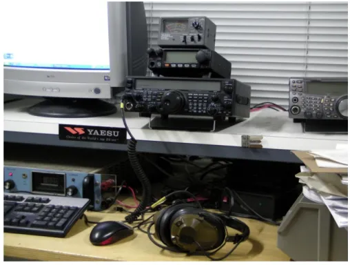
Figure 3.3 – Receiver and computer used to record the Argos signals in the ground station.
3.3 – Decoding Test
After receiving and recording the Argos uplink signals, the decoding stage began. The first goal was to analyze the received signals. Test if it was possible to demodulate them and verify the problems that eventually could surge during the process. This way, it was possible to check if the VORSat team had the tools needed to complete that task with success.
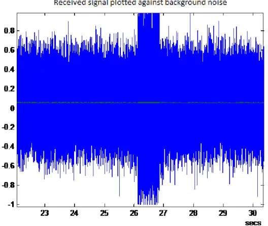
Next, the steps of the interpretation of a received signal from the 401,65 MHz built antenna will be presented. The signal was believed to be an Argos message and it had a frame rate of 44100 Hz. The program used was Matlab.
38 Argos Uplink Signals Reception and Analysis
38
Reading the audio signal and restricting the signal processing to just the part without noise.
Figure 3.4 – Received signal plotted against background noise.
39 Decoding Test
39
Next, the Fourier transform of the Argos signal was analised to measure the central frequency. As it shows in the pictures bellow a difference of 2412 Hz was observed in this case (notice that the receiver was tuned to 2 kHz below 401.65 MHz).
40 Argos Uplink Signals Reception and Analysis 40 -500 0 500 1000 1500 2000 2500 3000 3500 4000 4500 500 1000 1500 2000 2500 3000 3500 4000 4500 Hz Hz
Zoom on the frequency difference applied in the signal fc
2412 Hz
Figure 3.7 – Zoom on the frequency difference applied in the signal fc.
Then, analyzing again the Fourier transform of the Argos signal, but this time with the frequency value of the actual Argos signal fc, shifted to the origin, it was possible to plan a lowpass filter to achieve a cleaner signal interpretation. The designed filter had pass frequency of 620 Hz and frequency stop of 780 Hz.
41 Decoding Test
41
Figure 3.8 – Shifted Fourier transform of the shifted signal.
42 Argos Uplink Signals Reception and Analysis
42 Figure 3.10 – Lowpass filter design.
Finally, in order to decode the Argos signal, an angle function was applied to the filtered signal. Knowing that the signal was codified in Biphase_L and the Argos uplink message structure, it was possible to decode the signal observing the phase transitions throughout the signal and check if it was indeed an Argos message. In the demodulation of the signal it was obtained the Argos detection preamble – FFFE2F Hex; the message size – 9 Hex; the platform ID – 6420F Hex; the sensors data divided in four blocks of 32 bits: „CA7F0329-5ABF7652-5EC11A45-352E1DAE- 8C2DE109‟ Hex and a block for the checksum with 32 bits as well.
Therefore, it was proven that the audio signal received by the built antenna was in fact an Argos uplink signal.
43 Decoding Test 43 0 0.1 0.2 0.3 0.4 0.5 0.6 0.7 0.8 -500 -400 -300 -200 -100 0 100 200 secs Angle function of the filtered signal
0.36 0.365 0.37 0.375 0.38 0.385 0.39 0.395 0.4 0.405 -440 -420 -400 -380 -360 -340 -320 -300 -280 -260 secs Zoom on the signal bit transitions
Figure 3.11 – Angle function of the filtered signal.
44 Conclusions
44
3.4 – Conclusions
This chapter detailed the analysis of the received Argos uplink signal interpretation using the Matlab program.
It was a lengthy process since the actual interpretation had to be made manually observing each phase transition of the received signal angle function.
However, it is safe to say that there were no major problems in the Argos signal interpretation and that at that point the next step was trying to make the decoding of the Argos signals easier and faster.
45
Chapter 4
Development of the Decoding Program
In this chapter the functioning of the Argos uplink messages decoding program will be detailed. The software used was the Matlab program.
4.1 - Decoding Program Structure
The first goal at this stage was to develop a real time program that could autonomously decode the received Argos messages. It was necessary that the program could reproduce autonomously all the interpretation steps made in the manual signal interpretation detailed in above chapter, and in a more reliable way. Basically, the program had to be able to recognize through specific algorithms some crucial values for the signal processing. It had also to identify and decode each part of the Argos message since the preamble to the sensors data and report any errors that may occur.
The decoding program is divided in two major functions:
Main function - signal processing that has the responsibility of discriminate each
part of the message for its proper decoding and verify the existence of any possible errors.
Decoding function - Decodes the bits in the message carried by one of the
function inputs which is already aligned to start at the first sampler and translate the decoded bits into hexadecimal numbers (0 to 15).
When necessary an extra function input is supplied carrying the value (in degrees) of the last bit from the previous message. Then it returns a perfect differential signal that is regenerated from the decoded message for further comparison purposes. This will be explained later in this chapter.
46 Development of the Decoding Program
46
4.1.1 Baseline Considerations:
To the better understanding of the decoding program steps it is necessary to explain some facts relative the signal processing and program methods:
The method of discriminating the distinct parts of the message was achieved by comparison of predetermined generated signals with the received Argos signals through correlation. Whenever in the correlated signal occurs a peak it is known that one signal occurred in the other at that point and so that peak is used as a reference point for the decoding alignment process. Since it is known how the Argos message starts (with the preamble FFFE2F) a perfect signal identical to the preamble is generated. This enables by correlation the detection of the preamble in the received signal and subsequently serves as a reference to the start of the decoding process. Then to deal with the drafting issue that happens throughout the time on the signal, provoked by the processing delay of the emissary, the decoding of the message is not made all at once. It is separated in modules of 32 symbols. When one finishes, the starting decoding point is readjusted and the decoding starts all over again.
In both signals (received and generated) the phase values are not always 60º or -60º in each level of the signal as they were supposed to. So instead of using the original signals, it is used the differential of the signals in order to have a permanent and constant comparable feature (phase difference) in the signals that are going to be correlated. That is achieved by calculating the difference of the actual phase with the one that occurred 1/800 s before. The reason why the difference time reference is 1/800 s, lays on the fact that the codification used is the Biphase_L type at 400 bps. Which means that one symbol of two bits has the longevity of 1/400 s and therefore half a symbol (phase value changes every half a symbol) has the longevity of 1/800 s. In the differential signal the phase difference is near zero, 120º (60º-(-60º)) or -120º (-60º - (60º)).
47 Decoding Program Structure 47 0 0.1 0.2 0.3 0.4 0.5 0.6 0.7 0.8 -300 -200 -100 0 100 200 300 secs Differential of the angle function of the same signal
0 0.1 0.2 0.3 0.4 0.5 0.6 0.7 0.8 -500 -400 -300 -200 -100 0 100 200 secs Angle function of a received signal
Figure 4.1 – Angle function of a received signal.
48 Development of the Decoding Program
48
It is worth mentioning that the emissary compresses the signal to reduce its bandwidth, softening the abrupt level changes, turning the quadratic wave into a almost sinusoidal wave. Thus, the level transitions occurs at key points, to be exact, remembering that the Biphase_l codification works at 400 bps leading to a 2,5 ms per symbol, the level transitions happens at each half symbol, at each fs/800 samples of the signal.
Due to the phase modulation of ±60º (thus leaving a residual carrier) the spectrum of the transmitted signal is characterized by a significant peak at the carrier frequency. This feature is helpful in the determination of the Doppler shift of the received signal, which is the method employed by the ARGOS satellite instruments to locate tags. Also, it makes shifting the received message frequency band to the origin easy, as described below.
4.1.2 – Decoding Steps
Getting the frequency shift of the signal: the first issue on the development of
the program was to create an algorithm code to allow the program to detect by its own the frequency shift of the signal. The program had to recognize the peak value of the Upper sideband and determine its index that would be the shift frequency signal. That is achieved by finding the max value of the absolute values of the Fourier transform of the signal.
Bringing the signal to baseband and low-pass filtering: the received signal is
multiplied by the complex exponential of the shifting frequency in order to shift it to the origin. Then it is filtered by a FIR filter with frequency pass of 600 Hz and frequency stop of 850 Hz and the frame rate is decimated to 4800 sps from the original 44100 or 48000 sps. This makes the signal processing faster allowing the program to run in real time.
49 Decoding Program Structure
49
Figure 4.3 – Comparison between a non-filtered and a filtered signal.
Computing the differential phase (relative to the 1/800 s before) of the received signal: the program computes the differential phase of the angle
function of the received signal. This will be known as the half bit differential phase signal.
Verifying if it is an Argos message finding the preamble, FFF2EF, in the received data: knowing that in an Argos message the transmission time of the
pure carrier is near 160 ms and after that occurs the message preamble, it is generated a perfect differential signal of 126 zeros (160 ms with 1/400 seconds per symbol corresponds to 63 symbols and as the differential is relative to half a symbol before, it gives 126 half symbols) corresponding to the pure carrier plus the message preamble. That signal is then correlated with the half bit differential version.
Readjusting the decoding starting point to the preamble and checking if the preamble was correctly detected: the program correlates the differential of a
generated signal identical to only the message preamble (FFFE2F) with the differential of the received signal. Through the decoding function, the program verifies if it matches perfectly.
Decoding the next 24 bits, containing the message length and the ID of the Argos transmitter: the starting point is readjusted to the end of the preamble
and the decoding function, given the last bit of the preamble, decodes the next 24 bits saving the decoded numbers. Finally the differential of the decoded signal
50 Development of the Decoding Program
50
Number of words: Through the message length decoded symbols, the program
calculates the number of words (number of sensors data blocks) of the message. Verifying checksums: the program checks if there are no any errors with the
length and the ID decoding.
Decoding the remaining words: the decoding function already aligned with the
first sample of the first word (first block of 32 bits of the sensors data) starts decoding the rest of the Argos message. One word of 32 symbols after another, N times being the N the determined earlier number of words. At the end of each word decoding the decoded word is stored in a prepared vector and the starting decoding point is readjusted by correlation with the optimal signal corresponding to the decoded word. This procedure avoids loss of synchronization due to clock errors.
4.2 - Results
To test the Argos decoding messages program it was decoded the same signal that was analyzed and interpreted manually in the previous chapter to compare the results.
The decoding result of the Argos decoding program was:
ARGOS message received without errors:
Message length: 4 Transmitter ID: 12552 Message content: 9C420F CA7F0329 5ABF7652 5EC11A45 352E1DAE 8C2DE109
The developed decoding program obtained exactly the same decoded message that the one achieved by manual interpretation.
4.3 - Conclusions
It is safe to declare that the Argos decoding program development was a success since it decodes in real time and accurately received Argos messages.
51
Chapter 5
Argos signals Generation Test
The final objective of this thesis was to prove that the development of an Argos transmitter is viable by developing software that allowed a signal generator of the VORSat team to generate and emit Argos signals.
5.1 - Argos Signals Generator Program
The program was developed to generate stereo signals containing desired messages by the user that would be emitted by an I/Q modulator.
The Argos signal generator is structured by a single function where the inputs are: the message length; platform ID; the actual words that the user wishes to emit; the frequency sampler and the frequency offset. The Argos message preamble is generated by the program itself.
For clarity purposes, spaces and “–“can be used and not only the function returns the signal it also plays it.
5.1.1 – Considerations
Smoothing the angle transitions to avoid frequency leaks: to avoid frequency
leaks the generated signal was filtered with a tapered cosine window.
Smoothing the entry and finish of the generated signal: it was also applied a
tapered-cosine window and inserted a pure carrier at the beginning and at the end of the generated signal to smooth its entry and finish.
52 Argos Signals Generation Tests
52
5.2 - Results
In order to test the Argos signal generator program various signals were generated and emitted. By linking a computer prepared with the signal generator program to the VORSat team signal generator, it was possible to generate and emit signals. Each signal representing Argos messages with chosen messages by the user and emitted with the necessary power so the signal could be received by a receiver synched on the same frequency as the signal generator (401.65 MHz minus the ±2kHz shifting frequency) that was nearby (same room). The next step was to record the received signals through the sound board of the computer linked to the receiver and save them with the highest quality (48000 Hz, 16 Bit, Stereo). I/Q modulation was used in every emitted signal.
Figure 5.1 – Computer and signal generator used in the signals emitting.
Next, the analysis of one of the emitted signals will be presented: The chosen message of the generated and emitted signal was:
53 Results
53 Figure 5.2 - Emitted signal.
Applying the signal decoding program developed in this thesis to the emitted signal the result was:
Argos message received without errors:
Message length: 4 Transmitter ID: 6590 Message content: 866FAF 4152474F 534D4553 53414745 54455354 32332F31
After checking that the decoding was properly executed it was analyzed the quality of the emitted signal observing the phase transitions of the emitted signal.
54 Argos Signals Generation Tests
54
Figure.5.3 – Differential of the angle function of the emitted signal, as received in the vicinity.
Figure 5.4 – Zoom on the differential of the angle function of the emitted signal as received in the vicinity.
55 Results 55 0 0.1 0.2 0.3 0.4 0.5 0.6 0.7 0.8 0.9 -1 -0.8 -0.6 -0.4 -0.2 0 0.2 0.4 0.6 0.8 1 secs Received signal
As the above figures show the emitted signal presents high quality since the phase transitions throughout the whole differential signal are considerably regular(+120º,-120º).
The quality of the emitted signal was also compared with the one received and decoded referred signal in the previous chapter.
56 Argos Signals Generation Tests 56 0 0.1 0.2 0.3 0.4 0.5 0.6 0.7 0.8 0.9 -400 -300 -200 -100 0 100 200 300 400 secs Differential of the angle function of the received signal
0.3 0.31 0.32 0.33 0.34 0.35 0.36 0.37 0.38 0.39 -200 -150 -100 -50 0 50 100 150 secs Differential of the angle function of the received signal
Figure 5.6 – Differential of the angle function of the received signal.
57 Conclusions
57
As it can be observed the quality of the received signal is not as good as the one demonstrated by the emitted signal since it suffers some phase irregularities (the phase difference relative to the previous half symbol is not always ±120º when is not zero) in some parts of the signal, not enough to compromise its proper decoding though.
5.3 - Conclusions
To conclude it can be affirmed that both the received signal by the 401.65 MHz built antenna and the generated one presented satisfactory signal quality levels for proper decoding. However the emitted signal stood out due to its higher signal quality.
![Figure 1.1 – VORSat cube satellite [1].](https://thumb-eu.123doks.com/thumbv2/123dok_br/15713783.1069538/20.892.253.555.315.624/figure-vorsat-cube-satellite.webp)
![Table 2.1 - Evolution of Argos instrument capabilities [3].](https://thumb-eu.123doks.com/thumbv2/123dok_br/15713783.1069538/27.892.241.692.147.569/table-evolution-argos-instrument-capabilities.webp)
![Figure 2.1 - Principle of Doppler Effect [7]-](https://thumb-eu.123doks.com/thumbv2/123dok_br/15713783.1069538/28.892.202.651.229.549/figure-principle-doppler-effect.webp)
![Figure 2.2 – Argos PMT connected to a GPS receiver [7].-](https://thumb-eu.123doks.com/thumbv2/123dok_br/15713783.1069538/29.892.234.646.402.811/figure-argos-pmt-connected-gps-receiver.webp)
![Table 2.2 – Location error classes (Argos manual) [7].](https://thumb-eu.123doks.com/thumbv2/123dok_br/15713783.1069538/30.892.242.611.709.1130/table-location-error-classes-argos-manual.webp)
![Figure 2.6 – Argos/GPS tagged buoys [19].](https://thumb-eu.123doks.com/thumbv2/123dok_br/15713783.1069538/32.892.92.448.135.351/figure-argos-gps-tagged-buoys.webp)
![Figure 2.10 – GPS phone tag [22].](https://thumb-eu.123doks.com/thumbv2/123dok_br/15713783.1069538/33.892.295.640.156.347/figure-gps-phone-tag.webp)