Universidade de Lisboa
Faculdade de Ciências
Departamento de Física
Selective functionalization of
electrospun fibres
André Francisco Oliveira Girão
Dissertação
Mestrado Integrado em Engenharia Biomédica e Biofísica Perfil em Engenharia Clínica e Instrumentação Médica
Universidade de Lisboa
Faculdade de Ciências
Departamento de Física
Selective functionalization of
electrospun fibres
André Francisco Oliveira Girão
Dissertação orientada pelo Professor Doutor Lorenzo Moroni e pelo
Professor Doutor Hugo Alexandre Ferreira
Mestrado Integrado em Engenharia Biomédica e Biofísica Perfil em Engenharia Clínica e Instrumentação Médica
Acknowledgments
First of all, I would like to thank Professor Clemmens van Blitterswijk and Associate Professor Roman Truckenmüller for the opportunity of study in the Department of Tissue Regeneration at MIRA, institute of for biomedical technology and technical medicine of the University of Twente. My sincere appreciation is also extended to Associate Professor Lorenzo Moroni for have received me into his research group and proposing me this exciting project.
I owe my deepest gratitude to Maqsood Ahmed and Paul Wieringa for their teachings, patience and most important for their friendship. It was a great honor for me work and learn with Max and Paul during my master studies at University of Twente.
This work would not have been possible without the support and friendship of Professor Hugo Ferreira. I am grateful for his supervision and for having inspired me to look for new and exciting opportunities outside the University of Lisbon.
I was never by myself during my academic journey because my friends were always with me to make me feel at home. Thank you Andreia, Gil, João, Mariana, Melissa, Neuza and Patrícia. I know that you will never let me walk alone.
Finally, I would like to express my gratitude to my parents and sister for their motivation, support and kindness.
Resumo
A engenharia de tecidos é uma área multidisciplinar da engenharia biomédica que articula conceitos da química, física, engenharia e medicina com o objetivo de recuperar ou substituir uma função perdida de determinado órgão ou tecido. Um dos principais desafios desta área da biotecnologia é a criação de matrizes tridimensionais biocompatíveis e biodegradáveis que sejam capazes de garantir um suporte físico e bioquímico adequado à regeneração celular. Assim, as características mecânicas, químicas e biológicas destas matrizes devem ser adaptadas ao ambiente celular que se pretende reproduzir, dando origem quer à resposta celular específica das células cultivadas na matriz, quer à otimização da resposta fisiológica do próprio organismo.
Com efeito, dependendo da função a que se destina, as matrizes usadas em engenharia de tecidos variam tanto no biomaterial que lhes dá origem como na técnica de fabricação utilizada. As vantagens dos polímeros face aos outros materiais tais como biocompatibilidade, biodegradação, alta porosidade e boas propriedades mecânicas, tornam-nos no tipo de material mais utilizado na construção de matrizes tridimensionais. É o caso do copolímero PolyActive, já aprovado pela Food and Drug Administration (FDA) e utilizado em múltiplas aplicações em engenharia de tecidos, com especial destaque para a regeneração óssea. A versatilidade deste polímero está estreitamente relacionada com o rácio dos segmentos químicos que o constituem, um segmento hidrofílico de Politereftalato de etileno (PEOT) e outro hidrofóbico de Poli(tereftalato de butileno) (PBT), que ao ser modificado permite o controlo das propriedades mecânicas e químicas do material. Por outro lado, a eletrofiação é uma técnica de fabricação que tem crescido em termos de popularidade pois permite o fabrico de matrizes fibrosas capazes de simular detalhadamente a topografia das fibras de colagénio que compõem a matriz extracelular natural.
Tendo tudo isto em conta, neste estudo foram construídas matrizes tridimensionais de PolyActive por eletrofiação capazes de modular e guiar a resposta celular a partir de recursos topográficos e bioquímicos. A topografia das matrizes foi controlada com a introdução de elétrodos capazes deinfluenciar o campo elétrico e, assim, alinhar as fibras de PolyActive durante o processo de eletrofiação, que ocorreu num ambiente controlado para garantir a reprodução das propriedades das fibras. Já a incorporação de biomoléculas na superfície das fibras foi conseguida a partir da investigação de duas estratégias distintas.
Numa das abordagens, matrizes fibrosas de dois tipos de PolyActive (1000PEOT70PBT30 e 300PEOT55PBT45) foram expostas a irradiação ultravioleta (UV) com o objetivo de introduzir grupos químicos na superfície das fibras capazes de aumentar a adesão de biomoléculas. As diferenças entre superfícies tratadas e não
tratadas com UV foram analisadas com recurso às técnicas de espetroscopia de infravermelho médio com transformada de Fourier acoplada ao acessório de reflexão total atenuada (ATR-FTIR) e de fotoeletrões excitados por raios X (XPS). Os resultados mostram que os grupos funcionais resultantes da interação da superfície das fibras com o UV dependem do rácio PEOT/PBT e do conteúdo de Polietilenoglicol (PEG) presente no copolímero. Assim, as fibras de 1000PEOT70PBT30 (PA 1000) apresentaram um grande número de grupos carboxilo e hidroxilo na sua superfície devido à degradação do segmento de PEOT e da sua grande cadeia polimérica de PEG após 40 minutos de exposição à radiação UV. Por sua vez, a matriz fibrosa de 300PEOT55PBT45 (PA 300), quando sujeita ao mesmo período de irradiação UV, originou p-benzoquinonas na superfície das suas fibras devido ao alto teor cristalino da sua estrutura. Em ambos os casos, o tratamento UV aumentou as áreas de adesão das proteínas oriundas do meio de cultura celular e por conseguinte a adesão celular tornou-se também mais eficiente. Porém, a resposta celular é dependente não só das características das matrizes, mas também da linha celular utilizada. Por exemplo, as células Schwann de rato mostraram não só preferência pelas áreas ativadas pelo UV, mas também se mostraram sensíveis a pequenas alterações do alinhamento das fibras resultantes das diferenças entre os dois copolímeros. Foi também utilizada uma máscara de níquel para controlar espacialmente a introdução de novos grupos químicos nas superfícies das matrizes fibrosas de PA 300 e PA 1000.
A segunda estratégia apresentada consistiu na eletrofiação de fibras de PA 300 com grupos químicos incorporados para uma funcionalização posterior. Basicamente, uma solução polimérica composta por PA 300 e PEG com determinados grupos funcionais numa proporção 4:1 foi sujeita ao processo de eletrofiação, originando fibras de PA 300 com os grupos funcionais do PEG na sua superfície. Esta abordagem inovadora e inédita possibilitou a seleção dos grupos funcionais localizados na superfície das matrizes fibrosas e consequentemente o controlo do tipo de biomoléculas que vão aderir às fibras. Neste estudo foram utilizados dois tipos de PEG funcionalizado: PEG com terminais alcinos ((bis)PEG-Alkyne), que possibilitam a cicloadição azida-alcino com biomoléculas que tenham a função azida; e PEG com grupos terminais de N-hidroxisuccinimida ((bis)PEG-SVA), que facilitam a ligação com proteínas. As superfícies das matrizes de PA 300 + (bis)PEG-SVA e de PA 300 + (bis)PEG-Alkyne foram analisadas recorrendo às técnicas de ATR-FTIR e XPS. No primeiro caso, os resultados provaram a existência de N-hidroxisuccinimida na superfície das fibras, que depois foi confirmada com recurso a microscopia de fluorescência; relativamente às matrizes de PA 300 + (bis)PEG-Alkyne, apesar das técnicas de espectrometria não produzirem resultados conclusivos, foi possível confirmar a presença de alcinos na superfície das fibras a partir das imagens de microscopia de fluorescência.
O sucesso da segunda abordagem permite abrir as portas ao aparecimento de novas metodologias de design e fabricação de matrizes biofuncionais, já que torna possível a simulação e controlo do ambiente bioquímico que influencia as respostas celulares de uma forma simples e eficiente.
Abstract
The principal objective of a new generation of tissue engineering scaffolds is to reproduce the spatial and biochemical microenvironmental characteristics of the natural extracellular matrix (ECM) with the purpose of modulating the cell response and consequently enhance tissue repair. There is an enormous variety of scaffolding approaches that highly depend on the biomaterial selection, on the fabrication technique used and on the specific function of the scaffold.
In this study, bioactive electrospun scaffolds made of PolyActive (Poly(ethylene oxide terephthalate) / Poly(buylene terephthalate) (PEOT/PBT)) copolymer, capable of combining a spatially organized structure with bioactive factors, was developed. The design and fabrication strategies used to create the scaffolds allow the tailoring of the scaffold’s function by manipulating the introduction of specific chemical groups on its surface for further selective immobilization of complex biomolecules, resulting in the desired cell response.
In one approach, the surface of both 300PEOT55PBT45 (PA 300) and 1000PEOT70PBT30 (PA 1000) electrospun fibres were modified via UV exposure, resulting in the introduction of specific functional groups able to improve the protein adsorption process and consequently increase the available areas for cell attachment. A spatial definition of protein adsorption was accomplished by exposing the fibres via patterned mask.
An alternative strategy consisted of electrospinning PA 300 fibres with incorporated chemical groups for later functionalization. Alkyne and NHS-esters functional groups were successfully incorporated on the surface of the electrospun fibres via the introduction of specific PEG linkers ((bis)PEG-alkyne and (bis)PEG-SVA) in the electrospinning blend solution. This innovative methodology can be adopted for multiple tissue engineering applications since specific chemical groups can be introduced onto the surface of electrospun fibres, leading to a meticulous selection of the biochemical elements that will be adsorbed and consequently to a detailed control of the cell behaviour.
Keywords: tissue engineering scaffold; PolyActive; electrospinning; UV irradiation;
(bis)PEG-SVA; (bis)PEG-Alkyne; protein adsorption; click chemistry; Attenuated Total Reflectance Fourier Transform Infrared (ATR-FTIR); X-ray Photoelectron Spectroscopy (XPS).
Table of contents
List of acronyms ... 13 List of figures ... 14 List of tables ... 16 1. Introduction ... 17 1.1. Materials ... 17 1.1.1. PolyActive ... 19 1.2. Fabrication Techniques ... 26 1.2.1. Electrospinning ... 27 1.3. Scaffold function ... 302. State of the Art ... 31
2.1. Surface Modification of electrospun fibres ... 31
2.2. Electrospun fibres for the delivery of bioactive molecules ... 34
2.3. Fabrication of electrospun fibres with the defined structure ... 36
3. Aim ... 39
4. Materials and methods ... 40
4.1. Electrospinning ... 40 4.1.1. PA 300 ... 40 4.1.2. PA 300 + (bis)PEG-SVA ... 40 4.1.3. PA 300 + (bis)PEG-Alkyne ... 41 4.1.4. PA 1000 ... 41 4.2. UV treatment ... 41 4.3. Analysis techniques ... 41 4.3.1. NMR ... 41 4.3.2. ATR-FTIR ... 42 4.3.3. XPS ... 43
4.4. Protein adsorption tests ... 43
4.5. Click Chemistry tests ... 44
4.6. Cell culture ... 44
5. Functionalization of PolyActive electrospun fibres by UV exposure ... 46
5.1. Scaffolds characterization ... 46
5.3. Cell response ... 65
6. Electrospinning PA fibres with functional groups ... 69
6.1. PolyActive + (bis)PEG-SVA electrospun fibres ... 69
6.1.1. (bis)PEG-SVA/Amine reaction ... 69
6.1.2. Scaffold characterization ... 71
6.1.3. Protein adsorption ... 75
6.2. PolyActive + (bis)PEG-Alkyne electrospun fibres ... 76
6.2.1. (bis)PEG-Alkyne/Azide reaction ... 76
6.2.2. Scaffold characterization ... 78
6.2.3. Click Chemistry tests ... 81
7. Discussion ... 84
8. Conclusion ... 91
List of acronyms
3 D Three dimensional
ATR-FTIR Attenuated Total Reflectance Fourier Transform Infrared BSA Bovine serum albumin
CHCl3 Chloroform
cm Centimetre Cu(I) Copper(I)
ECM Extracellular Matrix
EDC 1-ethyl-3-(3-dimethylaminopropyl) carbodiimide FBS Fetal Bovine Serum
FDA Food and Drug Administration
FITC-BSA Albumin-fluorescein isothiocyanate conjugate from bovine HO. Hydroxyl radical
HFIP 1, 1, 1, 3, 3, 3-hexafluoro-2-propanol NHS N-hydroxysuccinimide
nm Nanometre
NMR Nuclear Magnetic Resonance PA PolyActive
PA 300 300PEOT55PBT45 PA 1000 1000PEOT70PBT30
PBS Phosphate buffered saline PBT Poly(buylene terephthalate) PEG Polyethylene glycol
PEO Polyethylene oxide
PEOT Poly(ethylene oxide terephthalate) PO. Alkoxy radical
POO. Alkylperoxy radical POOOO-P Tetraoxides POOH Hydroperoxide μm Micrometre UV Ultraviolet irradiation V Volume w weight wt % Weight percent
List of figures
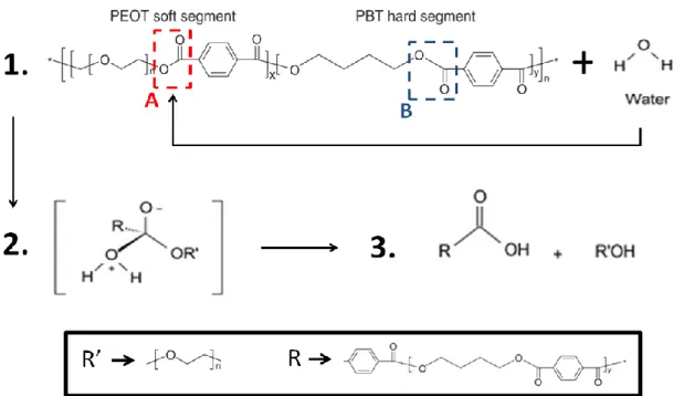
Figure 1 Chemical structure of PEOT/PBT copolymers. Page 19. Figure 2 Hydrolysis mechanism of PEOT/PBT in water. Page 21.
Figure 3 Oxidation of PEO: formation of alkoxy radicals via photo (hυ) and thermal (Δ) conditions. Page 22.
Figure 4 Oxidation of PEO: formation of the final products via three different pathways. Page 23.
Figure 5 Photo-oxidative reactions of PEOT. Page 24 Figure 6 Formation of Hydroperoxides on PBT. Page 25.
Figure 7 Two different pathways for the Formation of mono and di-hydroxy-substituted compounds. Page 25.
Figure 8 Schematic of the electrospinning process. Page 28.
Figure 9 Surface modification scheme for galactose conjugation to PCLEEP electrospun nanofiber scaffold. Page 34.
Figure 10 Coaxial electrospinning process. Page 37.
Figure 11 ATR-FTIR spectra of PA 1000 and PA 300. Page 47. Figure 12 H-NMR spectra of PA 1000 and PA 300. Page 48.
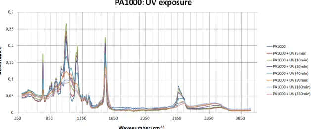
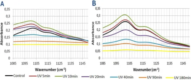
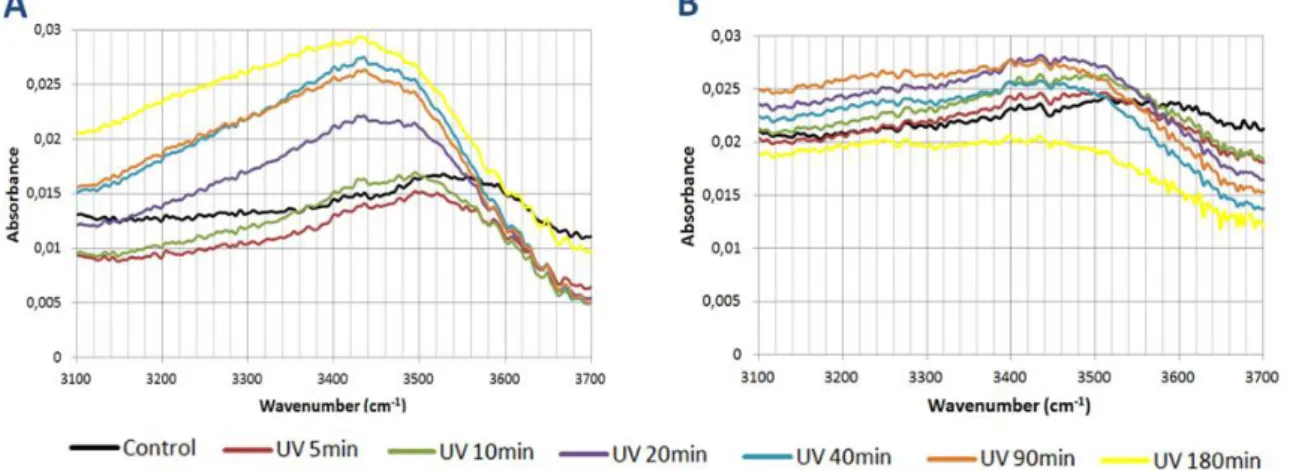
Figure 13 FTIR spectra of PA 1000 at various UV exposure times. Page 49. Figure 14 FTIR spectra of PA 300 at various UV exposure times. Page 49. Figure 15 Degradation pathways of phenol under the UV irradiation. Page 50.
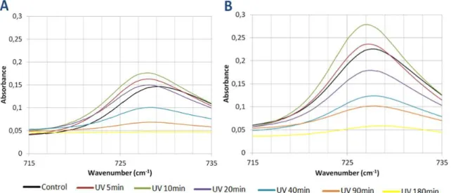
Figure 16 FTIR spectra of the C-H aromatic zone after various UV exposure times. Page 51.
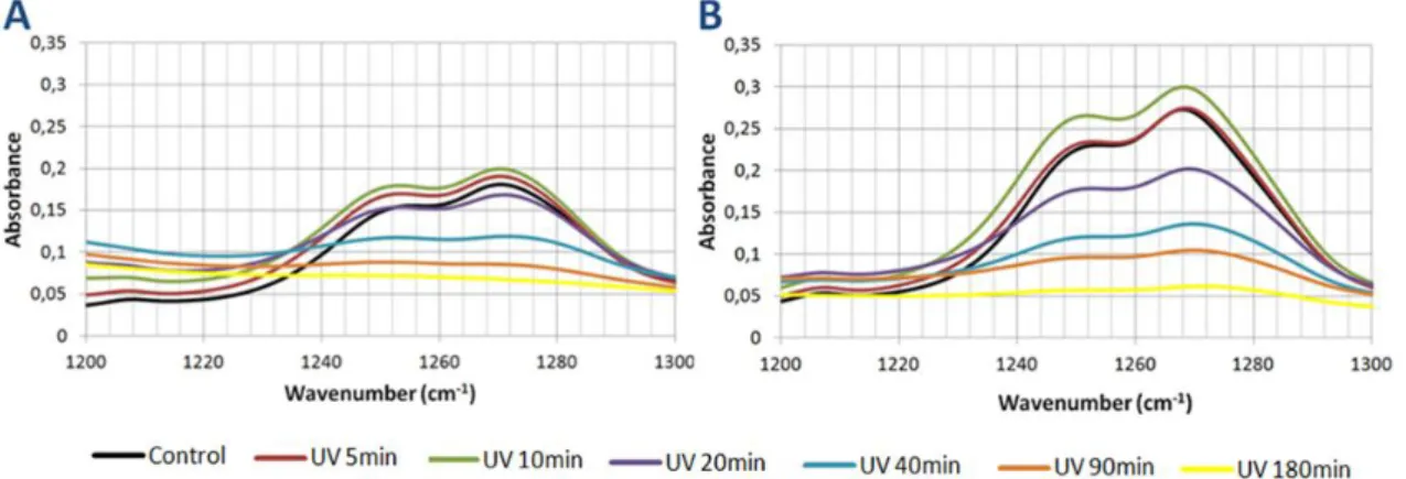
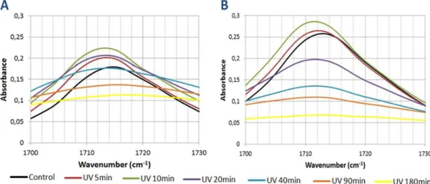
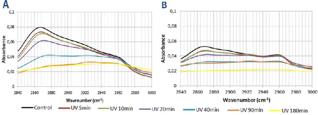
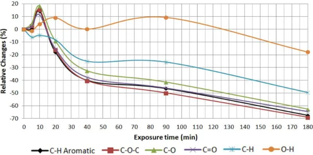
Figure 17 FTIR spectra of the C-O-C zone after various UV exposure times. Page 52. Figure 18 FTIR spectra of the C-O zone after various UV exposure times. Page 53. Figure 19 FTIR spectra of the C-O zone after various UV exposure times. Page 54. Figure 20 FTIR spectra of the C-H zone after various UV exposure times. Page 55. Figure 21 FTIR spectra of the O-H zone after various UV exposure times. Page 56. Figure 22 Spectra of the relative changes in different peak areas of the PA 1000 after
various UV exposure times. Page 57.
Figure 23 Spectra of the relative changes in different peak areas of the PA 300 after various UV exposure times. Page 57.
Figure 24 C1s peaks of PA 300. Page 60. Figure 25 C1s peaks of PA 1000. Page 60.
Figure 26 Mechanism of covalent attachment of carboxylic acid with protein via EDC/NHS complex. Page 62.
Figure 27 Representative fluorescence microscope images of PA 300. Page 63. Figure 28 Representative fluorescence microscope images of PA 1000. Page 63. Figure 29 Fluorescent microscope observations of PA 300. Page 64.
Figure 30 Fluorescent microscope observations of PA 1000. Page 64.
Figure 31 Fluorescent microscope observations of PA 300 + UV (40min / Mask) + BSA and PA 1000 + UV (40min/ Mask) + BSA. Page 65.
Figure 32 Rat Schwann Cells staining. Page 66.
Figure 34 Rat Schwann Cells staining: PA 1000 + 40min UV irradiation (UV Mask). Page 67.
Figure 35 Rat Schwann Cells staining. Page 67.
Figure 36 Rat Schwann Cells staining: PA 300 + 40min UV irradiation. Page 68.
Figure 37 Rat Schwann Cells staining: PA 300 + 40min UV irradiation (UV Mask). Page 68.
Figure 38 Molecular structure of (bis)PEG-SVA. Page 69.
Figure 39 Reaction of (bis)PEG-SVA with amines on proteins. Page 70. Figure 40 H-NMR spectrum of (bis)PEG-SVA. Page 71.
Figure 41 ATR-FTIR spectrum of PA300 + (bis)PEG-SVA. Page 71.
Figure 42 Comparison between the ATR-FTIR spectra of PA 300 and PA 300 + (bis)PEG-SVA. Page 72.
Figure 43 Comparison between the ATR-FTIR spectra of PA 300 and PA 300 + (bis)PEG-SVA. Page 72.
Figure 44 Comparison between the ATR-FTIR spectra of PA 300 and PA 300 + (bis)PEG-SVA. Page 73.
Figure 45 C1s peaks of PA 300 + (bis)PEG-SVA. Page 74.
Figure 46 Fluorescent microscope observations of PA 300 + (bis)PEG-SVA. Page 75. Figure 47 Two alternative pathways to the Huisgen 1,3-dipolar cycloaddition
reaction: thermal and Cu(I) catalyzed. Page 77. Figure 48 Molecular structure of (bis)PEG-Alkyne. Page 77. Figure 49 H-NMR spectrum of (bis)PEG-Alkyne. Page 77.
Figure 50 ATR-FTIR spectrum of PA300 + (bis)PEG-Alkyne. Page 78.
Figure 51 Comparison between the ATR-FTIR spectra of PA 300 and PA 300 + (bis)PEG-Alkyne. Page 79.
Figure 52 Comparison between the ATR-FTIR spectra of PA 300 and PA 300 + (bis)PEG-Alkyne. Page 79.
Figure 53 Comparison between the ATR-FTIR spectra of PA 300 and PA 300 + (bis)PEG-Alkyne. Page 79.
Figure 54 C1s peaks of PA 300 + (bis)PEG-Alkyne. Page 81.
Figure 55 Fluorescent microscope observations of PA 300 + (bis)PEG-Alkyne after incubation in a Azidedye /PBS solution. Page 82.
Figure 56 Fluorescent microscope observations of the negative control PA 300 after incubation in a Azide-dye / PBS solution. Page 82.
Figure 57 Fluorescent microscope observations of the negative control PA 300 + (bis)PEG-Alkyne before incubation in a Azide-dye / PBS solution. Page 83. Figure 58 Incorporation of functionalized PEG linkers on the surface of electrospun
scaffolds by two different strategies. Page 88. Figure 59 Segregation of a mixed cell population. Page 90.
List of tables
Table 1 PEO content (wt%) of PEOT/PBT copolymers produced with PEG of different molecular weights at diverse soft to hard segment ratios. Page 20.
Table 2 Relative Changes in the C-H aromatic peak area for PA1000 and PA 300 during UV exposure. Page 51.
Table 3 Relative Changes in the C-O-C peak area for PA1000 and PA 300 during UV exposure. Page 52.
Table 4 Relative Changes in the C-O peak area for PA1000 and PA 300 during UV exposure. Page 53.
Table 5 Relative Changes in the C=O peak area for PA1000 and PA 300 during UV exposure. Page 53.
Table 6 Relative Changes in the C-H peak area for PA1000 and PA 300 during UV exposure. Page 54.
Table 7 Relative Changes in the O-H peak area for PA1000 and PA 300 during UV exposure. Page 56.
Table 8 PA 1000 elemental composition before and after 40 minutes of UV irradiation. Page 58.
Table 9 PA 300 elemental composition before and after 40 minutes of UV irradiation. Page 58.
Table 10 Fractions of various functional groups from PA 1000 C1s peaks. Page 59. Table 11 Fractions of various functional groups from PA 300 C1s peaks. Page 59. Table 12 Comparison between the ATR-FTIR peak areas of PA 300 and PA 300 +
(bis)PEG-SVA. Page 73.
Table 13 PA 300 + (bis)PEG-SVA elemental composition. Page 73.
Table 14 Fractions of various functional groups from PA 300 + (bis)PEG-SVA C1s peaks. Page 74.
Table 15 Comparison between PA 300 and PA 300 + (bis)PEG-SVAfunctional groups from N1s peaks. Page 75.
Table 16 Comparison between the ATR-FTIR peak areas of PA 300 and PA 300 + (bis)PEG-Alkyne. Page 80.
Table 17 PA 300 + (bis)PEG-Alkyne elemental composition. Page 80.
Table 18 Fractions of various functional groups from PA 300 + (bis)PEG-Alkyne C1s peaks. Page 81.
17
1. Introduction
Tissue engineering is an interdisciplinary area that applies the principles of clinical medicine, mechanical engineering and materials science to increase and optimize the body’s natural response after tissue or organ damage. This field relies extensively in the use of 3D scaffolds able to provide suitable microenvironments that should mimic the natural extracellular matrix, providing both topographical and chemical cues to enhance cell adhesion, proliferation and differentiation towards new tissue formation.
Currently, there are two major tissue engineering approaches. The most popular strategy follows the idea that the new tissue should come from an implant with pre-cultured cells. In this approach, the seeded cells are usually isolated from the host target tissue and they should proliferate in an appropriate 3D dimensional scaffold, before implantation. The other strategy explains that, immediately after injury, an acellular scaffold should be implanted into the defect area. This particular scaffold should be functionalized with specific biomolecules able to recruit progenitor cells towards the injured area, and then promote their proliferation and differentiation with the purpose of regenerating the wounded tissue. Both strategies can also be combined since a functionalized scaffold can be useful in an ex-vivo situation by inducing cell seeding, proliferation and differentiation in order to encourage tissue formation after implementation in vivo. In this approach it is expected that the scaffold could continue to release signalling molecules with the purpose of enhancing the regeneration of the defect area, even after implementation [1].
In the light of these strategies, to achieve success in tissue engineering, it is necessary to combine and balance the role of cells, scaffolds and biomolecules. To accomplish that, it is crucial that the scaffold not only provides the physical support, but also the chemical agents that will modulate the injury microenvironment. Generally, the scaffold for tissue engineering should present good levels of biocompatibility and biodegradability as well as an architecture and mechanical properties adapted to its specific purpose. So, there are three main topics that should be considered during the scaffold design: choice of the material, manufacturing technology and the final function of the scaffold.
1.1. Materials
The choice of a suitable material is a crucial step in the development of scaffolds for tissue engineering applications since the selected material will be responsible for facilitating the generation of a useful size and volume of tissue, allow
18
an efficient delivery of molecular and mechanical signals to the cells and it should also support the cells and optimize their function within the scaffold. In fact, as the goal of the scaffold is to mimic the advantageous characteristics of the natural extracellular matrix (ECM), the scaffolding material should present physical, chemical and biological properties that enhance biocompatibility and biodegradability in order to avoid unwanted host tissue reaction of the immune system and the damage of the tissues via toxic products, respectively [2,3,4].
Some of the most common categories of biomaterials used in the fabrication of scaffolds for tissue engineering are ceramics, natural polymers and synthetic polymers.
Ceramic scaffolds are mostly used in bone regeneration applications, such as grafting in bone replacement and coating metal implants, because of their mechanical stiffness, low elasticity and hard brittle surface. The most frequent biomedical ceramic is hydroxyapatite (HA) because of its structural and chemical similarity to the mineral phase of the native bone that assures biocompatibility as well as osteoblast differentiation and proliferation. However, ceramics also proved to be difficult to shape for implementation and tricky to adapt to other clinical applications due their brittleness and porous network structure [5,6,7].
In contrast to the ceramic scaffolds, polymers offer design flexibility since the composition, structure and arrangement of their constituent macromolecules can be adapted to different functions. Generally, polymers present appropriate properties for tissue engineering applications like biocompatibility, high surface-to-volume ratio, high porosity, biodegradation and good mechanical features [8]. There are two main types of polymers used as biomaterials: natural polymers and synthetic polymers.
The natural polymers have a very elevated potential for achieving clinical success because they normally exhibit high levels of biocompatibility, biodegradability and low immunogenicity, which consequently enhance the cells performance in the biological systems. They can be classified as proteins (e.g. collagen and gelatin), polysaccharides (e.g. alginate and chitosan) or polynucleotides (DNA, RNA) [8,9]. Natural biomaterials, especially collagen based biomaterials, have been successfully used to support growth of axons and also to deliver multiple cell types into the nervous system after injury. Indeed, the importance of collagen in nerve regeneration applications can be exemplified by the three conduits made of collagen type I for peripheral nerve system regeneration already approved by the FDA (Food and Drug Administration): NeuraGen®, NeuroflexTM and NeuroMarixTM [10]. Besides nerve tissue engineering, natural polymers are currently used in several areas of tissue engineering such as bone tissue engineering [11] and they are also utilized as DNA carriers for gene delivery applications [12].
19
Relative to the natural polymers, synthetic polymers offer some advantages which includes great design flexibility, reproducibility under controlled conditions and the control of both physical and chemical material properties like porosity, biodegradability and biocompatibility. In addition to this, they are cheaper and represent a more consistent source of raw materials than natural polymers; however there is a higher risk of rejection due the reduced biocompatibility comparing with natural polymers. Typically, the synthetic polymers used in tissue engineering applications are either hydrophobic biodegradable polyesters, such as polyglycolide (PGA), polylactide (PLA), poly(ε-caprolactone) (PCL), or hydrophilic biodegradable polymers like Polyethylene oxide (PEO). Synthetic polymers can be easily combined in order to generate new biomaterials with desirable properties; in this way it is possible to create a material able to conjugate the mechanical properties of the hydrophobic polyesters with the cell affinity of the hydrophilic polymers. For example, poly-dl-lactic-co-glycolic acid (PLGA) is a very versatile and well studied synthetic copolymer that has shown very good performances in mimicking the microenvironment that supports the cells. Some applications include bone [13] and nerve tissue engineering [14]. In fact, some copolymers like Degrapol® and PolyActive® have already found clinical use and are both already FDA approved.
1.1.1. PolyActive
The wide range of mechanical properties like elasticity, toughness and strength in combination with easy processability and high levels of biocompatibility offered by the copolymers of poly(ethylene oxide terephthalate)-poly(buylene terephthalate) (PEOT/PBT), make this class of copoly(ether ester)s one top candidate for tissue engineering applications [15,16].
Like other segmented block copolymers, the properties of PEOT/PBT, are determined by the characteristics of the constituting segments: the hydrophilic poly(ethylene oxide terephthalate) segment adds the soft elastomeric, hydrogel-like behaviour into the copolymer while the hydrophobic poly(buylene terephthalate) introduces rigidity (Figure 1)[16,17].
Deschamps et al. [16,18] have described the preparation of PEOT/PBT as a two step polycondensation of polyethylene glycol (PEG), 1,4-butanediol and dimethyl
20
terephthalate (DMT) in the presence of titanium tetrabutoxide as catalyst and Irganox 1330 as antioxidant. Firstly there is a transesterification of PEG, DMT and 1,4-butanediol under a nitrogen atmosphere at 180ᵒC, then after two hours, the pressure slowly decreases (from 1000 to 0.1mbar) and the temperature is, at the same time, increased to 240ᵒC in order to enable polycondensation. The composition of the block copolymers is designated as aPEOTbPBTc, where a is the starting PEG molecular weight, b the weight percentage of PEOT and c the percentage of the PBT hard segments. The soft segments weight contribution (b) is related not only with the contribution of PEO (polyethylene-oxide) and the terephthalate ester units (T) present in the soft segments, but also with the starting PEG molecular weight (Table 1).
The variations in the soft and hard segments ratio and in the PEG’s molecular weight used during the PEOT/PBT copolymers synthesis have different effects on the phase separation of the system and consequently in the tailoring of characteristics such as wettability [19,20], swelling [20], biodegradation rate [16,18], protein adsorption [19] and mechanical properties [16,20]. As the different macromolecules of block copolymers are covalently linked, the macrophase separation is unable to occur; however, microphase separation can still happen [16]. Therefore, the phase separation will be more distinct if there is an increase in PEOT length and in the PBT sequence with further crystallization of these blocks or in the polymers that contain high molecular weight PEG [16].
The swelling capacity and other polymer features like the flexible and plastic behaviour are highly influenced by controlling the polymer mesh size, that is, the effective length of the soft segment between the physical crosslinks. Thus a larger PEO content will result in a larger network mesh size and consequently in an improvement in the swelling ability and viscoelastic parameters. In contrast, decrease of the elastic moduli of the polymer will be noted [17,20].
The PEOT/PBT copolymers have been also extensively investigated in terms of
in vitro and in vivo biocompatibility [18,21] and there are two major types of
Table 1. PEO content (wt%) of PEOT/PBT copolymers produced with PEG of different molecular weights at diverse
21
degradation process that can occur: hydrolysis of the ester bonds and oxidation of the ether bonds [16]. Because of the PEOT/PBT molecular structure, the degradation mechanisms rates varies from very low for low PEG molecular weight and high PBT content to high for larger contents of PEOT and longer PEO segments [21].
During the hydrolytic degradation of the PEOT/PBT block copolymers in an aqueous media (Figure 2), the hydrophilic domain is more accessible to water uptake; this is because the ester bond present in the PEOT segment (ester A) is more liable to be attacked by water due the great hydrophobicity of the PBT segments [22]. Firstly, the hydrolysis will cause chain scissions of the PEOT segments and consequently provoke an entanglement of the remaining chain molecules, which will then reorganize themselves from a disordered state to an ordered state [22]. The continuous water absorption and the presence of carboxyl acids, that are resulted from the reaction, will initiate new chain scission events and eventually the ester bond in the crystalline region (ester B) will be also attacked by water; ultimately, the whole molecule is broken into pieces [16,22].
Unlike hydrolysis, the PEOT/PBT oxidation mechanism can easily occur in the presence of air and, similarly to other polymers containing PEO, it originates scission of the polymer chain via free radical reactions [16]. These radicals are usually produced by photonic activation of chromophores, which can be present either as internal (in-chain) impurities such as hydroperoxides or carbonyls, or external impurities like
Figure 2. Hydrolysis mechanism of PEOT/PBT in water: 1) The ester bond in the PEOT segment is attacked by water; 2) The H from H2O joins to the oxygen atom in the OR’ part of the original ester and the OH part of the H2O joins to
22
polymerization catalyst residues or pollutants from the atmosphere [23,24]. Another possible sources of chromophores include unsaturated groups like C=O or C=C [25,26].
When the formation of the chromophoric radical occurs in the PEO segment, it will lead to the formation of a macroradical in the polymer backbone by hydrogen abstraction of the carbon atoms in the α-position to the oxygen. The macroradical will then react with atmospheric O2 and produce an alkylperoxy radical (POO.). After that,
a new abstraction of a labile hydrogen from the same neighbouring macromolecule can lead to the formation of a hydroperoxide (POOH) that will be decomposed by thermal and photo degradation to generate an alkoxy radical (PO.) and a hydroxyl radical (HO.) (equation 1)[23,27]. An alternative pathway that describes the formation of the alkoxy radical is the recombinations of the alkylperoxy radicals following the Russell type mechanism [23,27,28]. This bimolecular recombination is described by the equation 2, where the peroxy radicals recombine and produce unstable tetraoxides (P-OOOO-P). At the end of the reaction mechanism, the P-OOOO-P decomposes to give two alkoxy radicals in a cage and an oxygen molecule (Figure 3) [23,27].
equation 1 equation 2
23
The reaction presented in equation 2 is more common during photo-oxidation of PEO; on the other hand equation 1 usually happens when the PEO thermo-oxidation occurs. After the formation of the alkoxy radical, the oxidation process may proceed by three different pathways, depending on the environment conditions: β-scission, reaction with a hydroxyl radical and hydrogen abstraction reaction of alkoxy radical (Figure 4) [23,29].
The β-scission of the radical leads to the formation of formate end groups that can be produced directly from the scission or from a supplementary pathway, where the oxidation of the macroradicals generated from the scission will lead to the formation of primary hydroporoxides. These primary hydroporoxides because of the thermal and photo-degradation will also produce formates [23].
Other alternative route leads to the formation of ester functions because of the reaction of alkoxy radicals with hydroxyl radicals under thermo-oxidative conditions. Alternatively, the alkoxy radical can be involved in a hydrogen abstraction reaction which will form a thermal unstable hemiacetal that will be decomposed to alcohols and carboxylic acids [23,29].
Morlat et al. [23] have studied the PEO oxidation mechanism and concluded that the photo-oxidative conditions favour the β-scission of the alkoxy radicals and consequently the generation of formats in a ratio of 5:1 against chain esters. On the
24
other hand, under thermo-oxidative conditions the production ratio of formates and esters are similar [23,30].
Besides the PEO oxidation mechanism, the PEOT segment can offer an alternative oxidation mechanism via the terephthalate ester units (Figure 5). The key event in this degradation process is also the scission of the polymer main chain that generates carboxyl end groups, volatile products such as CO and CO2 and it can also
produce mono or dihydroxy terephthalates [31].
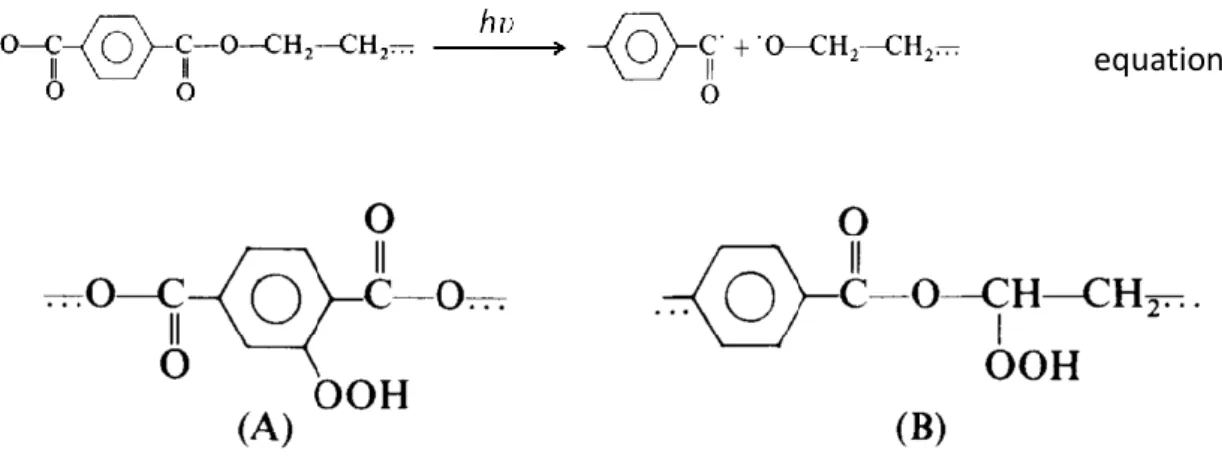
Relative to the PBT segment, the oxidation process is a complex mechanism in which both photolytic and photo-oxidative reactions interfere [32,33]. The activation of the chromophore groups can lead to three direct photo-scission processes (equations 3, 4 and 5) that will generate primary radicals [32]. These radicals are able to provoke the oxidation of the carbon atom located in the α-position to the oxygen ester by abstraction of labile hydrogen atoms, leading to the formation of hydroperoxides. During photo-oxidation, there is also possible that some hydroperoxides are formed on the aromatic rings (Figure 6) [32,33].
equation 3 equation 4
25
equation 5
In both cases presented in Figure 6, the homolysis of the hydroperoxides O-O bond generates alkoxy and hydroxyl radicals [33,34]. The alkoxy radicals located on the aromatic ring are able to participate in a hydrogen abstraction reaction involving the polymer chain that will lead to the formation of mono and di-hydroxy-substituted compounds [33,35]. These compounds can also be produced if the hydroxyl radicals, originated from the O-O homolysis at the ester’s α-carbon, react with the aromatic rings of the PBT segment (Figure 7) [33]. The characteristic yellowing of the samples containing PBT can be related to the formation of these compounds and with their further degradation [36].
Figure 7. Two different pathways for the Formation of mono and di-hydroxy-substituted compounds. Adapted
from [35].
Δ or
Δ or
Figure 6. Formation of Hydroperoxides on PBT. a) on the aromatic ring; b) on the α-position to the oxygen
26
The alkoxy radicals produced by the degradation of the unstable hydroperoxides in the carbon α-position will follow a similar chain of reactions showed in the Figure 5 [32].
In summary, the PEOT/PBT copolymers are excellent candidates as scaffolds in the engineering of both hard and soft tissues because of the easy adaptable properties described above and the good results in the in vivo and in vitro biocompatibility tests, which have allowed the FDA approval for clinical applications as cement stopper and bone filler in orthopaedic surgery (PolyActive
®
) [15,18,20].1.2. Fabrication Techniques
There are several techniques to shape polymers into advantageous, complex and reproducible scaffolds that exhibit useful properties for specific tissue engineering applications. The selection of one fabrication technique deeply depends on the desired purpose of the scaffold and the bulk and surface properties of the material.
Fibrous scaffolds are very popular since they can successfully mimic the architecture of the native extracellular matrix at the nanoscale level. In fact, the diameter of the nanofibres that form the scaffold apparatus ranges from 1 to 1000 nm, matching the size scale of extracellular matrix fibres such as collagen (50 to 500 nm). In addition to this, the combination of the high surface area to volume ratio with the microporous structure of the nanofibres enhances cell adhesion, proliferation, migration and differentiation [8,37,38]. There are three production methods that are commonly used to produce fibrous scaffolds: phase separation, self assembly and electrospinning.
Phase separation is a method used to build scaffolds by thermally inducing the separation of a homogeneous polymer solution into a multiphase system, which comprises a polymer-poor phase (low polymer concentration) and a polymer-rich phase (high polymer concentration). Generally, phase separation begins with a polymer dissolution that is followed by a liquid-liquid phase separation process. Then, the upper critical temperatures originate both polymer-poor phase and polymer-rich phase via polymer gelation. At the end, the polymer-rich phase solidifies to form a matrix and the polymer-poor phase originates pores due the solvent removal. The fibre diameter can be modulated by selecting appropriate gelling temperature (high temperatures lead to microfibres and lower temperatures originate nanofibers); on the other hand, the polymer concentration influences the mechanical properties (tensile modulus and tensile strength) of the fibres. Although the phase separation technique do not require specialized equipment and assures the desired shape for the scaffold, it can only be performed by a limited number of polymers (e.g. PLGA and chitosan) and it offers little control over the pre size distribution [37,38,39].
27
The self assembly process can be defined as an autonomous organization of components such as biomolecules into complex structures due to noncovalent bonds or weak covalent interactions such as electrostatic, van der Walls and hydrophobic interactions. So, in order to build fibrous scaffolds it is necessary that small units like proteins assemble into nanofibres with high aspect ratio, which can mimic the in vivo microenvironment of the cells. In fact, this approach can be applied in vivo in order to create a nanofibre system able to connect neighbouring cells and consequently organize a three dimensional network capable of mechanically support them. For example, a peptide amphiphile (PA)-based-self-assembling system allows the generation of thermally stable protein-like nanofibres with the purpose of mimicking the extracellular matrix; one possible application of this system uses the changes of the microenvironment pH to induce self assembly processes for bone tissue engineering. However, self assembly is not a very common approach for tissue engineering purposes as it is limited to few polymers and it has low economic viability [37,38,39].
Electrospinning is the most popular fabrication technique to create fibrous since it simpler and more cost effective, compared with both self assembly and phase separation. Because of that, the electrospinning principles will be discussed in detail in the following section.
1.2.1. Electrospinning
Electrospinning is a fairly time- and cost-efficient technique that is used to produce ultrafine micro or nanofibres with considerable surface areas and porosity, flexibility in surface functionalities and advanced mechanical performance (stiffness and tensile strength).
The equipment needed for the electrospinning process includes a syringe pump, a high voltage source and a collector. The procedure is relatively simple and it basically involves the formation of polymer fibres due to electrostatic repulsion of a polymer solution (Figure 8). At the beginning of the process, the polymer solution is held to the needle tip of the syringe (spinneret) via surface tension. Then, the introduction of an electric field originates mutual charge repulsion within the polymer solution that is directly opposite to the surface tension. Upon reaching a critical voltage, the electrostatic force generates localized charges that counterbalance with the surface tension of the polymer solution at the spinneret tip, leading to droplet elongation and stretching until a conical shape known as the Taylor cone is formed, and a continuous jet is ejected. Initially, the polymer jet travels directly towards the grounded collecting plate; however, it will deviate from the most direct path, resulting in a spiralling and further stretching, when the charge density (that increases with the increasing distance from the spinneret) overcomes the surface tension. Finally, the
28
polymer jet thins in air because of the elongation and the evaporation of the solvent, leading to the formation of electrospun fibres on the target [37,38,40].
Electrospinning can be performed using a wide range of polymers. In fact, several synthetic polymers like poly(lactic acid) (PLLA), poly(lactic-co-glycolic acid, poly(e-caprolactone) (PCL) and Polyethylene glycol (PEG) have been successfully used to electrospin nanofibres for several tissue engineering applications. For instance, Shin et al. [41] have construct a nanofibre-based PLGA scaffold with the potential of enhanced articular cartilage reconstruction. In another example, hBM-MSCs were able to produce cartilagineous extracellular matrix after being successfully cultured in PCL electrospun nanofibres for cartilage tissue engineering purposes [42].
Natural polymers such as collagen or chitosan can also be electrospun; however they are usually blended with synthetic polymers or salts in order to increase the solution viscosity and consistency [38,40]. For example, Jeong et al. [43] have electrospun composite alginate/ chitosan by adding PEO to the polymer solution. The authors used the ability of this synthetic polymer to increase the polymer chain entanglements and decrease the conductivity of the charged polysaccharide solutions in order to aid the electrospinning process.
29
The sizes of the electrospun fibres are typically between 200 nm and 5 mm, depending on the conditions. In fact, fibre morphology can be easily controlled by adapting the parameters of the electrospinning process. These parameters can be classified in system parameters, process parameters and ambient parameters [37,40].
The system parameters are mainly associated with the solution properties such as viscosity/polymer concentration, conductivity, surface tension and polymer molecular weight. Generally, increasing the viscosity of the solution by increasing polymer concentration leads to the formation of uniform fibres (without beads and junctions) with larger diameter. Variations in the conductivity by adding salt normally result in small diameter fibres with fewer beads present. A decrease on beading can also be accomplished with higher molecular weight polymers. The effects described above can be very difficult to isolate due the inter-connected relationship between all the polymer solution parameters. For example, it is very common that the conductivity variations affect the viscosity of the polymer solution [37,44,45].
On the other hand, the process parameters are related with the controlled variables such as flow rate, electric field strength, distance between the spinneret and the collector, needle tip design and collector composition and geometry. The effects on the fibre morphology after an increase on the applied voltage are increased beading and decreased diameter. On the other hand, increasing distance from the collector can result in decreased fibre diameter and decreased fibre wetness due the longer evaporation time of the solvent from the nanofibres. Contrary, when the flow rate increases, there are an increment in fibre wetness and bead formation [37,44,45].
The ambient parameters like humidity and temperature are also important for tailoring the nanofibres. As the increasing of the temperature leads to a decrease of the polymer viscosity, the electrospun fibres usually present a smaller diameter. The humidity can affect the morphology of the fibre by the appearance of pores. Although there are studies that corroborate these results, these parameters are poorly understood because their effects depend on the type of polymer, polymer-solvent combination, molecular weight and polymer hydrophilicity [44,45].
Overall, electrospinning has been distinguished as an efficient and versatile technique for the fabrication of polymer micro or nanofibres. In fact, the electrospun scaffolds can be tailored in order to mimic the native extracellular matrix and consequently support the attachment and proliferation of a large variety of cell types. Regardless, it can be a big challenge to engineer scaffolds with complex structures using only the electrospinning approach.
30
1.3. Scaffold function
The term “bioactive scaffold” is currently applied in the tissue engineering field to describe a scaffold capable of not only supporting the cells physically and mechanically, but also enhancing cell adhesion, migration and proliferation as well as phenotype choice via biochemical agents. The goal of these scaffolds is to recreate the functions of the extracellular matrix in a temporally and spatially organized structure [1].
In this way, the function of an optimal scaffold would be providing cell guidance and all aspects of cell response in a similar way as the ECM. Generally, the functions of the ECM include providing structural support and mechanical properties for cells to reside, bioactive cues to enable cells to respond to various signals of their environment, a flexible physical environment to allow a quick and efficient remodelling in case of tissue dynamic process like wound healing and it also act as reservoir of biomolecules and mediates their release. Currently, the scaffolds are able to closely mimic all this features due the physical and chemical characteristics of the materials used and also the microfabrication techniques selected. As explained above, electrospinning can efficiently produce nanofibres with similar dimensions as the collagen fibres from the natural extracellular matrix [46,47].
In terms of bioactivity, scaffolds can be adapted to interact with the cellular components and consequently facilitate and regulate their actions in a dynamic way. In order to accomplish that, the chemistry of the surface should not be only dependent on the properties of the bulk material, but also on the incorporation of biological cues like cell-adhesive ligands (e.g. fibronectin) to promote cell attachment [46]. For example, the surface properties of the poly-acrylonitrile methyl acrylate (PAN-MA) electrospun scaffold were improved by fibronectin adsorption, which proved to influence both the Schwann cells migration and the neurite outgrowth from dorsal root ganglion culture [48]. The scaffolds could also be used as reservoirs or delivery structures for biomolecules such as growth factors. Both hydrogels and electrospun fibres are very popular examples of this type of approach [1,46]. In fact, Holland et al. [49] have managed to create a oligo(poly(ethylene glycol)fumarate / gelatin (OPF/gelatin) hydrogel able to simultaneously deliver insulin-like growth factor-1 (IGF-1) and transforming growth factor-β1 (TGF- β(IGF-1) in a controlled manner to cartilage tissue engineering applications. Similarly, Wang et al. [50] have accomplished to release recombinant human bone morphogenetic protein (rhBMP-2) from an electrospun scaffold for bone tissue engineering applications. Besides the biological cues, it is also important that the scaffold provides physical cues like topography to modulate cell morphology and alignment [46]. In tissue engineering approaches, the incorporation of biological and mechanical cues on the surface of the scaffold usually occurs after application of some specific surface modification technique.
31
2. State of the Art
The combination of natural and synthetic polymers can optimize the physical and biological properties of the electrospun scaffolds, as well as mimic the morphology of the extra cellular matrix. However, in order to reach advanced biological and therapeutic applications, the surface of the fibres should be able to immobilize some active agents such as proteins and therapeutic genes without compromising the bulk properties.
For tissue engineering purposes, the role of the immobilized biomolecules on the nanofibres surface should be comparable to the function of the biochemical cues present in vivo during tissue regeneration, which is enhancing the specific phenotype and organization of the cells. According to this, several techniques of surface modification such as plasma and radiation treatment are being used on the surface of the electrospun scaffolds to directly enhance cell attachment and proliferation via protein and peptides adsorption. A complementary approach can be followed in the event of the adsorbed biomolecules are further released into the cell environment in a controllable and localized way to promote cell differentiation and proliferation.
In addition to the tissue regeneration proposes, the nanofibre meshes could be also used in drug delivery applications since the highly interconnected open nano-porous structure provides an extremely high surface area to volume ratio that results in a considerable drug loading amount per unit mass.
The electrospinning modality can also influence the properties of the surface by inducing diversification on the performance of the scaffolds. Indeed, the electrospinning technique can be adapted in order to control the composition of the core-shell structure of the fibres or to modulate the surface patterning by topographic cues.
In this way, it is important to understand which techniques are commonly used on surface functionalization and what advantages each one brings into tissue enginnering applications (section 2.1). The biomolecule delivery approach will be presented in section 2.2 and the applications that come from different electrospinning modalities will be explained in section 2.3.
2.1. Surface Modification of electrospun fibres
The main goal of the surface modification techniques is introduce functional groups on the surface of the electrospun fibres able to immobilize secondary bioactive molecules, guaranteeing at same time good biocompatibility levels and the preservation of the fibres morphology and their bulk properties [51,52].
32
Gas plasma treatment is a common, suitable and versatile technique that is mainly employed to generate functional groups such as hydroxyl, carboxyl and amino groups on the polymer surface. Normally, it results in an increase of the surface wettability without changing the bulk properties of the material or causing degradation; moreover, it can be used in complex shaped surfaces and it is a solvent free technology [51,53].
Plasma is a high energy state of matter, in which an oxygen or nitrogen containing gas or an inert gas is partially ionized [51,53]. There are two major categories of plasma: the thermal plasmas that cannot be used for biomedical polymers functionalization due to the high temperatures of the gas; and the non thermal plasmas that can be utilized in tissue engineering applications since the combination of low gas temperature and high electron temperature is able to originate chemical and physical changes on the surface without causing any thermal damage [53].
For tissue engineering applications the appropriate selection of the gas (oxygen, air or ammonia) used in the plasma treatment is a critical topic because it decides the functional groups that will be introduced on the target surface and consequently the specific biomolecules that can be covalently immobilized (e.g. collagen, gelatin, laminin and fibronectin) [54,55]. Poly(L-lactic acid)-co-poly(ε-caprolactone) electrospun fibres treated with air plasma were able to immobilize collagen on their surface and consequently improve the attachment, spreading and viability of the coronary artery endothelial cells [56]; in a similar example, Argon plasma treatment was used by Duan et al. [57] in order to build a collagen coated poly(ε-caprolactone) electrospun scaffolds capable of enhancing the attachment, spreading and proliferation of human dermal fibroblasts. In other cases, electrospun PLLA nanofibres pre-treated with plasma were used to adsorb laminin [58] and cationized gelatin [59] for neural and cartilage tissue engineering applications, respectively.
The wet chemical processes like hydrolysis and aminolysis are also suitable approaches to create new functionalities on the surface of biomedical polymers. The procedure involves the reaction between the scaffold and liquid reagents under basic or acidic conditions to generate functional groups by random chemical scission of the ester linkages on the backbone chain located on the surface. Indeed, the degraded and water insoluble polymer fragments, that result from the wet chemical process, are able to generate carboxylic, hydroxyl and amino groups [51,53,54]. Although this process is relatively simple since it does not require specialized equipment, the results are often non specific and non reproducible [53]. So, the duration of the hydrolysis and the concentration of the hydrolysing agents are essential to optimally produce
33
functional groups without altering significantly the bulk properties of the scaffold [51,54].
The applications of the wet chemical process concerning electrospun fibres are mostly related with bone tissue engineering applications. One example was developed by Jim et al. [60] who were able to create a suitable environment for the proliferation and function of osteoblasts using an electrospun poly(ε-caprolactone) (PCL) fibrous scaffold treated by a controlled hydrolysis in a NaOH medium.
The use of radiation is another method used in tissue engineering applications to modify biomedical polymer surfaces. The most common category of irradiation technique uses ultraviolet light (UV); however there are other types of radiation able to introduce chemical groups on scaffolds’ surfaces such as gamma radiation, ozone treatment and ozone combined with UV irradiation. The goal of the radiation approach is to generate reactive areas that can become functional groups or can be used to initiate grafting of monomers or graft polymerization. In fact, radiation is a simple and clean surface modification method since it does not require chemical additives or catalysts, though the dependence on the energy source can lead to nonspecific and non permanent degradation of the polymer backbone [51,53].
The surface modification via UV irradiation is commonly used in tissue engineering applications due its direct effect on protein adsorption and consequently on the cell adhesion process [61]. For example, Welle et al. [62] were able to modify the surface of electrospun Poly(propyl carbonate) (PPC) fibres via deep UV irradiation in order to increase the adsorption of proteins that stimulate cell adhesion. The study showed positive results with both L929 fibroblasts and primary rat hepatocytes cell lines. The UV irradiation can be also used to photo-reduce the Ag+ ions within cellulose acetate (CA) nanofibres to build antimicrobial separation filters [63]. Basically, the CA nanofibres electrospun from a combined CA / AgNO3 solution were irradiated with UV
light with the purpose of producing Ag nanoparticles on their surface.
The relevance of the graft polymerization induced by UV irradiation in the construction of advanced and specific electrospun scaffolds was discussed by Chua et al. in several reports. In one example, the polyethersulfone (PES) electrospun nanofibre scaffold was firstly carboxylated by UV-initiate poly(acrylic acid) (PAAc) grafting and then functionalized with amino groups to facilitate the adhesion and expression of umbilical cord blood hematopoietic stem/progenitor cells (HSPCs) [64]. In another approach followed by the same author [65], a nanofibre scaffold functionalized with galactose was used to study the attachment, the phenotype and the functional maintenance of rat hepatocytes. This strategy is summarized in the Figure 9: initially the Poly(acrylic acid) (PAAc) was grafted onto the surface of the electrospun poly(e-caprolactone-co-ethyl ethylene phosphate) (PCLEEP) scaffold via UV irradiation; then, the surface carboxyl (COOH) groups were covalently conjugated
34
with 1-O-(60-aminohexyl)-D-galactopyranoside (AHG) via N-hydroxysulfosuccinimide (sulfo-NHS) / 1-ethyl-3-(3-dimethylaminopropyl) carbodiimide (EDC) complex in order to allow cells attachment through galactose - asialoglycoprotein receptor (ASGPR) interactions.
Besides the UV irradiation treatment, there are other valid options like gamma irradiation that can be used on surface modification procedures. For instance, it can be used to graft Acrylic acid (AAc) on Poly(L-lactic co-poly-ε-caprolactone) (PLCL) for further immobilization of gelatin; this strategy was applied in a study of the adhesion, spreading and proliferation of human mesenchymal stem cells (hMSCs) by Shin et al. [66]. Using a similar electrospun scaffold, but utilizing photo-grafting Arg-Gly-Asp (RGD) containing peptide instead of gelatin, it was possible study the adhesion and proliferation of the MC3T3-E1 pre-osteblastic cells [67].
2.2. Electrospun fibres for the delivery of
bioactive molecules
The surface of the electrospun scaffolds can be chemically functionalized with the purpose of achieving sustained delivery of bioactive molecules. This means that instead of having proteins immobilized on the surface to enhance cell adhesion, the scaffolds should ensure the bioactivity of the incorporated biomolecules and fit their release profile within the adequate time frame [1]. The signalling molecules used depend on the function of the scaffold: cell division can be stimulated by mitogens; the
Figure 9. Surface modification scheme for galactose conjugation to PCLEEP electrospun nanofiber scaffold
35
migration, proliferation and differentiation can be accomplished by the release of proteins such as growth factors and the control generation of tissue form can be due to the morphogens action [68].
Although growth factor delivery scaffolds are usually fabricated using hydrogels due their defined three-dimensional polymer networks that allows easy incorporation of proteins, their limitations like poor mechanical properties, cell death in the depths of the scaffold and the impossibility of having a controlled release over a long time period [69,70] have turned electropun fibres into a viable alternative for protein delivery approaches. Indeed, the electrospun scaffolds can easily act as a drug carrier since their structural characteristics allow good dissolution rate, relative ease of drug incorporation and limited time for dug crystallization [71].
Besides the protein release issue, electrospun scaffolds could also be adapted for gene delivery. The differences between the scaffolds are related with the particularities of both delivery systems: contrary to the growth factors, which act extracellularly by binding to cell surface receptors, target genes must enter into the host genome of endogenous cells, transforming them into bio-activated actors able to produce therapeutic proteins. So, the target genes are usually packed within vectors (viral and non-viral) before incorporation into the scaffold in order to protect the genes from degradation [1].
Physical surface adsorption is a simple approach to load biomolecules into electrospun scaffolds. Basically, the fibres are dipped into an aqueous phase (solution or emulsion) containing biomolecules, which consequently attach to the scaffold via electrostatic forces. For example, BMP-2 was released by a poly(D,L-lactide-co-glycolide)/hydroxyl-lapatite (PLGA/HAp) electrospun scaffold to enhance bone regeneration after being successfully adsorbed by the fibres [72]. The PLGA/Hap electrospun scaffold also proved to be very promising as a DNA delivery device since it was also tested for encapsulation of BMP-2 plasmid DNA/chitosan nanoparticles. The DNA/chitosan nanoparticles released from the PLGA/Hap fibres proven to have a remarkable intracellular effect in the human marrow stem cells (hMSCs) by improving their attachment, viability and transfection efficiency of DNA [73].
In another method named blend electrospinning, biomolecules are mixed within the polymer solution in order to electrospin a hybrid scaffold. As this strategy localizes the biomolecules (e.g. proteins) within the fibres of the scaffolds, it allows more sustained release profiles compared to physical adsorption [1,51]. The common protein release from blend electrospun scaffolds is divided in two periods: during the first 24 hours a burst release occurs due a certain fraction of proteins that are located on the surface of the scaffold; after this period, a sustained release close to a linear mode is observed because of either the protein diffusion process or the polymer degradation process combined with protein diffusion. So, different polymers with
36
specific properties will originate unique release behaviours [1]. Besides the release profile, the preservation of the biological activity of the biomolecules is a very important prerequisite in designing electrospun scaffolds with the purpose of delivery [51]. For example, basic fibroblast growth factors were introduced into PLGA fibres and their release favoured bone marrow stem cell attachment, proliferation and differentiation [70]. Blend electrospinning was also used to build a PEO/ Bovine serum albumin (BSA) scaffold [74] and a PLLA / laminin electrospun scaffold capable of enhance PC12 cell viability and neurite outgrowth [58].
2.3. Fabrication of electrospun fibres with the
defined structure
The function of the electrospun scaffolds can be modulated through the use of several innovative electrospinning techniques that permit the fabrication of multi-layered electrospun fibres and the control of topographic cues.
The core-shell structure is a very useful nanofibre scaffold shape because this structure is capable of containing bioactive agents such as proteins, drugs and enzymes within the core and consequently control their release kinetics. The electrospinning modality used to fabricate this kind of scaffold is called coaxial electrospinning, in which both polymer solution and biological solution are coaxial and simultaneously electrospun without direct mixing by using two aligned syringes (Figure 10). As explained in the section 1.2.1, during coaxial electrospinning, it is necessary to apply appropriate parameters in order to fabricate a suitable electrospun scaffold. Therefore, several factors like feeding rate of the inner and outer fluids, interfacial tension and viscoelasticity of the two solutions can influence the process output by affecting the entrapment of components in the core part and the dimensions of both inner and outer diameters [1,51].
Coaxial electrospinning was recently used for both tissue engineering and drug delivery applications since the release profile includes an initial burst released followed by a sustained release period, which is analogous to the one from blend electrospun scaffolds presented in the previous section. However, the initial burst release from the coaxial electrospun fibres is inferior in volume and consequently more prolonged because of the core characteristics that work as a reservoir system with a biodegradable polymer barrier able to control the biomolecules diffusion rate [1,51]. For example, Sahoo et al. [70] have showed that PLGA coaxial nanofibres are capable of sustaining the release of bFGF from its core for two weeks, a much longer period than the release profile of basic fibroblast growth factors incorporated in a PLGA / bFGF blend scaffold. The release kinetics of proteins from coaxial electrospun scaffolds was thoroughly studied by Zhang et al. [75] that have encapsulated fluorescent-labeled
37
BSA protein along with PEG in PCL nanofibres with variable dimensions. The report indicated that the release rate is fibre size dependent, which means that smaller-sized fibres have a faster release then the larger ones. These results were able to provide basis for further design and optimization of protein delivery from coaxial electrospun fibres for several tissue engineering applications. For instance, the coaxial electrospun methodology was successfully applied in the building of a composite poly(lactic acid-caprolactone) / nerve growth factor (P(LLA-CL)/NGF) nerve conduit able to promote sciatic nerve regeneration in rats [76].
Besides the chemical rearrangement of the electrospun fibres, the physical organization and orientation of the fibres also play important roles during the design of the scaffold. This is because the scaffolds should replicate the natural structure of the extracellular matrix, which contains components that are arranged into extremely organized structures to control cell responses [51].
For tissue regeneration applications, the alignment of the fibres can be a critical feature since the cells cultured on such scaffolds are able to recognize the geometry and then align themselves along the fibres [51]. There are two major methods that can be used to accomplish aligned electrospun fibres: high speed rotating drum collector and stationary gap collector.
The use of the rotating drum collector is a simple and mechanical method of aligning the fibres along the circumference of the cylindrical drum. Basically, the collector (grounded or negatively charged) rotates at a high surface speed (over 1500 rpm) to make the electrospun fibres align along the rotating axis. Although it generates