Mohammad Masoumi
a,⁎
, Luis P.M. Santos
a, Ivan N. Bastos
b, Sergio S.M. Tavares
c,
Marcello J.G. da Silva
a, Hamilton F.G. de Abreu
aaUniversidade Federal do Ceará (UFC), Centro de Tecnologia, Departamento de Engenharia Metalúrgica e de Materiais, Campus do Pici Bloco, 714, Pici, 60455-760 Fortaleza-CE, Brazil b
Instituto Politécnico-UERJ-Rua Bonfim, 25-Vila Amelia, 28625-570 Nova Friburgo-RJ, Brazil
cUniversidade Federal Fluminense, Departamento de Engenharia Mecânica/PGMEC, Rua Passo da Pátria, 156, CEP 24210-240 Niterói/RJ, Brazil
a b s t r a c t
a r t i c l e
i n f o
Article history: Received 13 August 2015
Received in revised form 3 November 2015 Accepted 24 November 2015
Available online 29 November 2015
Crystallographic texture and grain–boundary distribution are introduced as a new method of reducing
suscepti-bility to crack formation and propagation. In this work, slow strain rate tests (SSRT) were performed on fully mar-tensitic ultra-high strength Fe–18Ni–Co steel in 0.6 M NaCl atmosphere at−1.2 VSCEto investigate hydrogen embrittlement (HE). Micro and meso-texture in both crack stricken and crack free regions were characterized using electron backscattering diffraction (EBSD) technique, tofind a pattern between crystallographic orienta-tion and HE susceptibility. The Taylor factor analysis was used to determine the grains with higher susceptibility to crack initiation and propagation. The results showed that cracks can initiate and propagate throughb100N// ND oriented grains, while {111} and {110}//NDfibers indicate higher resistance path for crack propagation. More-over, the high amount of deformed fraction with high stored energy acts as one of the main reasons for high sus-ceptibility of this steel against SSRT. It is concluded that the sussus-ceptibility of high strength Fe–18Ni–Co steel to HE
can be reduced through crystallographic texture control and grain boundary engineering.
© 2015 Elsevier Ltd. All rights reserved. Keywords:
Crystallographic texture Slow strain rate tests Crack propagation
1. Introduction
The low carbon, high nickel-cobalt steel can provide an extraordi-nary combination of strength, fracture toughness, good weldability and simple heat treatment[1,2]. These steels have their application rec-ognized in parts of ultra-high strength and great dimensional precision equipment. In these steels, transforming to martensite after a solution annealing following by water quenching, is not critical. High nickel con-tent with low carbon concon-tent, allows the formation of an outstanding tough BCC martensite. It is worth mention that the crystallographic structure of iron–nickel martensite with very low carbon content is body-center cubic (BCC structure). Jones and Li[3,4]concluded that austenite to martensite transformation in the iron–nickel system is a diffusionless type. The iron–nickel equilibrium diagram is shown in
Fig. 1. This diagram shows that when the alloy with 18% nickel is held at high temperature (above 650 °C), its structure consist entirely of austenite with FCC austenite structure. While at temperatures below 350 °C, a unique BCC structure is obtained regardless of the cooling rate. It is expected that the Maraging steels with 18% of nickel needs to be heated above 650 °C to be completely transformed to austenite. Howev-er, adding another alloy element, cobalt for example, it must be heated
to a minimum 800 °C to assure complete transformation to austenite. Previous investigations clearly showed that aging at 480 °C achieves the maximum strength and fracture toughness. Fe–18Ni–Co steels are mainly used in applications such as aerospace, military and production tooling[5]. Hydrogen embrittlement (HE) is a major problem in the high strength low carbon steels with martensitic microstructure. The re-sistance of steels to HE has been improved with reduction in alloying el-ement contents such as sulfur and niobium, inclusion control and low segregation in microstructures[6]. These lines of action have not con-firmed to be fully effective[7]; therefore, the crystallographic texture and grain–boundary engineering have been recommended to further reduce these alloys susceptibility to HE.
In steels, characteristic crystallographic orientation changes take place during deformation and heat treatment. Such changes, the texture effects, can be best explained on crack formation under strain and se-vere conditions like H2S environment[8]. In bcc structure, slip occurs in the close packedb111Ndirections but the slip plane may be any of the planes {110}, {112} or {123}; each of these planes contains the closed packed slip direction,b111N[9]. Dillamore et al.[10], by analyz-ing various types of steels based on dislocation theories and the misori-entation dependency on the grain orimisori-entation concluded that the elasticity modulus is the highest along theb111Ndirection and de-creases according to the sequence E111NE110NE112NE100. It can be concluded that the yielding occurs preferentially along theb100N ⁎ Corresponding author.
E-mail address:[email protected](M. Masoumi).
direction and plastic deformation would happen sooner along the other directions. Finally, cracks would nucleate at these preferred orientations.
The present work was done with the aim of looking for the potential HE crack initiation and propagation along preferred crystallographic orientations. In order to achieve it, SSRT was performed on fully bcc martensitic steel and crystallographic texture and grain boundaries dis-tribution were used to analyze crack nucleation and propagation sites to avoid catastrophic fractures. Then, the Taylor factor analysis was done on two cracked regions to predict the deformation tendency of grains.
2. Experimental material and methods
The chemical composition of the high strength Fe–18Ni–Co steel used in this study is given inTable 1. Specimens with dimensions of 12 × 11 × 3 mm were solution annealed at 820 °C for 1 h, air cooled to room temperature, aged at 480 °C for 3 h followed by air cooling in order to achieve a fully bcc martensitic structure. An XRD result of spec-imen is shown inFig. 2, where only a bcc structure was observed in this condition.
The main objective of this research was to study the crack initiation and propagation andfind a correlation between the probability of crack-ing and grain boundary characteristics. Therefore, SSRT were conducted with a strain rate of 1.0 × 10⁻⁶s−1. The tests were conducted in air and immersed in an 0.6 M NaCl electrolyte using a simultaneous potential charge at−1.2 VSCEat room temperature, according to ASTMG129-00 and ASTM F1624-09[11]. Relative strength and plasticity losses were chosen to assess the HE susceptibility of the materials. Cylindrical sam-ples of 4.1 mm in diameter and 28 mm in gauge length were employed
[12]. The sample was solution annealed at 820 °C for 1 h then aged at 480 °C for 3 h andfinally air cooled. Thus, the hardness 52.0 HRC was reached. The heat treatment was performed in a vacuum sealed quartz tube. The region of the samples exposed to the electrolyte were pre-pared using SiC paper up to 600 mesh, washed in distilled water and
blow dried. The samples were charged for 24 h before and during the SSRT by potentiostatic method. The tests were performed in a Cortest® machine model Constant's Extension Rate Test.
Microstructural examination was performed on metallographic samples grinded using SiC papers with mesh size up to 1200, then polished with 6, 3 and 1μm diamond paste andfinally etched with Marble's reagent[26]. For this investigation, an Olympus® BX–51 M op-tical microscope and a Philips® XL–30 scanning electron microscope (SEM) were used.
Ultimate tensile strength and elongation decreased dramatically during SSRT. For better understanding the effect of crystallographic ori-entation on HE behaviors, both crack stricken and crack free regions were selected throughout the mentioned specimen. It is worth men-tioning that the distance between examined areas is far enough to ig-nore interaction effects between them. Crystal orientation maps were obtained using an EBSD on a FEI, XL-30 SEM equipped with a HKL Oxford® camera using Channel 5 software. In the EBSD measurements, grain orientation, grain boundary types and Taylor factor were ana-lyzed. Taylor maps were calculated by the data sets using the primary
Fig. 1.Equilibrium phase diagram of Fe–Ni[36].
Table 1
Chemical composition of high strength Fe–18Ni–Co steel.
Element Ni Co Mo Ti Al Fe
regions leading to the martensite-to-austenite transformation. It is worth mentioning that many authors[14,15]have reported that a low carbon bcc-martensite leads to a better toughness compared to body-centered tetragonal (BCT) martensite. Also, the earlier research[16] re-ported that solution treatment can reduce the segregation of alloying el-ements and decrease corrosion and failure susceptibility. Furthermore, SEM micrograph is shown in Fid. 3b, indicated that the microstructure consists essentially of aligned lath martensite with grain size about 15 ± 2μm.
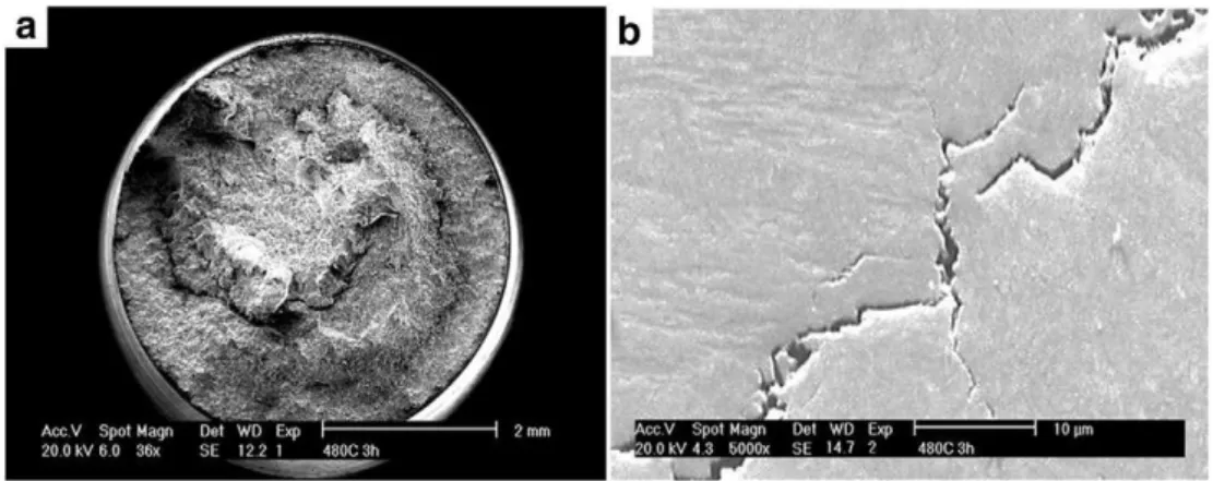
The fracture surface of the sample after SSRT experiment (Fig. 4a) demonstrated cup-and-cone fracture morphology, characteristic of a ductile failure. The extensive plastic deformation (necking) was ob-served around the fracture due to ductile failure behavior. Martensite is a non-equilibrium phase involving unstable dislocation substructure, excess vacancy concentrations and supersaturated interstitial solutes
[17], resulting high susceptibility to crack formation. In addition, it is ex-pected that hydrogen trapped at defect sites generates high-stress con-centration, decrease the ductility and facilitates failure.Fig. 4b shows the SEM micrograph of the studied sample after SSRT experiment. The cracks were developed propagating through intergranular and transgranular paths. It is expected (hypothesized) that crystallographic texture and grain boundaries distribution play a significant role on crack damage. Therefore, special attention will be paid to the analysis by EBSD of cracked regions.
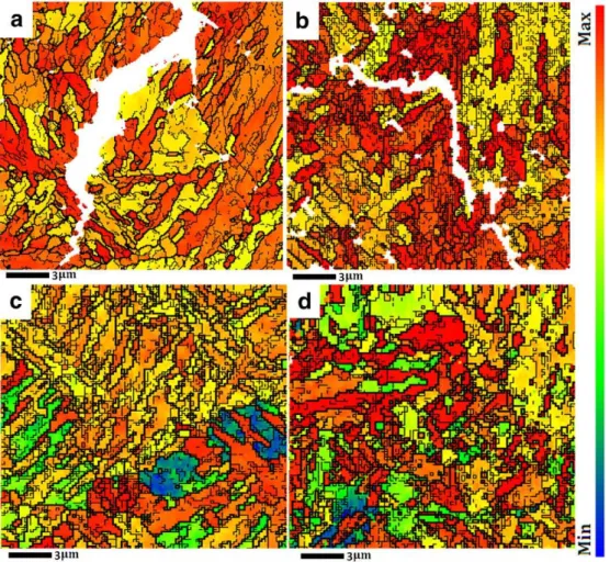
Fig. 5shows the EBSD inverse polefigure maps (IPF) from two cracks stricken and cracks free regions of the investigated samples. Sub-grains and low angle grain boundaries (LAGBs) of lower than 15° and high angle grain boundaries (HAGBs) higher than 15° of misorientation are shown as thin and thick lines, respectively. The high density of disloca-tion due to plastic deformadisloca-tion and the high strainfields seen near the grain boundaries of the IPF maps had some influence on the EBSD anal-ysis leading to poor indexing in these sites. It should also be considered that due to the restrictions imposed by angular resolution, boundaries with misorientation greater than 2° are identified as sub-grain bound-aries in the EBSD maps. It can be seen inFig. 4a and b, the cracks
versely proportional to the square root of the grain size[18]. However, reducing in grain sizes increases both strength and ductility. The brittle fracture is attributed to the insufficient number of slip systems. Grain re-fining is one of the effective ways to active more slip systems and im-proves the ductility[19]. As it was shown, the grain sizes in cracked regions are twice as big as non-cracked areas. It leads to fewer activated slip plan and decrease in crack formation resistance. Conversely, Yazdipour et al.[20]reported that HE resistance occurs in an optimum grain sizes. They explained thatfine grains that have a high number of grain boundaries could hinder crack propagation. While, veryfine grains provide high stored energy in grain boundaries, and a high vol-ume fraction of hydrogen can be trapped, facilitating crack propagation.
Fig. 6shows the texture represented byφ2= 45° sections of the ori-entation distribution function (ODF) calculated from the EBSD measure-ments. It is worth mentioning that ODFs were calculated just for small defined areas near the cracks. Thus, it clearly cannot present the crystal-lographic texture for the whole sample.
Fig. 6shows that in crack stricken regionsð112Þ½110φ1= 16°,ϕ= 24°,φ2= 45° and (001)½130φ1= 25 and 65°,ϕ= 0°,φ2= 45° had a dominant texture in samples a and b, respectively. Machová et al.[21]
proposed that, in bcc materials regarding compact plane and preferred slip direction, deformation needs three free displacements in the [100, 010, 001] directions. While these orientations would generate shear strain in atomic bonds, provide a preferred cleavage plane through the material. Therefore, grain boundaries related to {001}//ND have the lower resistance to damage deformation and are preferred sites to crack nucleation and propagation. In contrast, components (552)½115 φ1= 90°,ϕ= 75°,φ2= 45° andð221Þ½110 φ1= 21°,ϕ= 80°, φ2= 45° dominated textures are seen in regions c and d, respectively. Wassermann[22]argued that in steels at larger strains, twinning oc-curred preferentially in crystals of the former orientation, which were thereby rotated to {552}b115N. Normal slip would then result in the de-velopment of the observed {110}b001Norientation. Watanabe[23] in-dicated that twinning is generally crack-resistant due to their(its) low energy configurations.
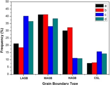
Fig. 7shows the grain boundary distribution, by type (LAGBs, medi-um angle grain boundaries–MAGBs, HAGBs, Coincidence site lattices– CSLs) and frequency of occurrence, in the hydrogen induced cracking (HIC)-free and HIC-stricken regions of the sample. The grain boundaries with misorientation angles less than 5°, 5–15° and higher than 15° are defined as a low, medium and high angle grain boundaries, respectively. It can be seen that the number fraction of LAGBs in cracked regions is significantly lower than non-cracked areas. In contrast, the highest frac-tion of HAGBs is shown in cracked regions. The grain boundaries repre-sent crystal defects and poor match of crystal planes along the boundary. The HAGBs possess higher energy due to dislocation accumu-lation; whereas, the low energy of LAGBs suggests adjacent grains are better arrangement. The development of HAGBs on cracked regions due to the absorption of dislocation into random boundaries. This mech-anism suggested that the development of boundaries misorientation in-creases stored energy in this zone. In contrast, development of LAGBs
during SSRT might be concluded by subgrain formation. It involves some dislocation annihilation and the rearrangement of the others into LAGBs. Furthermore, Huang[24]confirmed the growth of subgrains in {110}b001Ncrystal orientations, which, is fully compatible with the grin orientation in non-cracked regions. Some elongated grains with many subgrains have been observed (Fig. 5c, d). However, the grain boundaries and dislocation cells absorb the dislocations inside the grain, leading to an increase in the number of HAGBs in cracked regions. Thus grain boundaries are clearer and wider than in other regions. It is worth mentioning that an increase in dislocation piles-up at HAGBs forms the micro-voids and cracks. Therefore, the crack can propagate by incorporation of these micro-voids and cracks[25]. In summary, the grain boundary strengthening decreases, with increasing in fraction of LAGBs leading to improve the HE cracking.
It has been found that the MAGBs and CSLs are crack resistant due to their low energy configurations, whereas HAGBs are prone to crack
Fig. 4.SEM fractographs of sample with different magnification at cracked regions after SSRT.
while the boundaries are mainly linked to the {001} orientation is prone to crack formation. According to the related ODF of both cracked regions, it can be concluded that LAGBs, MAGBs, and CSLs linked to {001}//ND cannot stop the crack initiation and propagation. While in other free cracked regions, LAGBs, MAGBs and CSLs linked to {111} and {110} are more effective in preventing crack nucleation.
It is also important to point out the evolution of different types of CSL boundaries. The detailed CSL boundary character distributions obtained from the plane orientation are presented inFig. 8. The identifications of the CSL boundaries were limited up toΣ29 type which is a well-established criterion for such purpose because beyondΣ29, the bound-aries are usually considered to have the same properties as those of the random high angle boundaries.
CSL boundaries play a special role in determining the properties of materials. The number fraction of CSL boundaries in all regions of the
micrographs is shown inFig. 8. It has been found that an increase in the fraction of low-Σ(3≤Σ≤29), in samples c and d, is relative to the enhancement in crack resistance[27,28]. Furthermore, CSL boundaries are composed mainly ofΣ3,Σ9,Σ11,Σ25b andΣ27a, which, related tob111Nandb110Ndirections as previously explained, boundaries are more effective to prevent crack nucleation. It is notable thatΣ3 boundaries indicated as twin boundaries, however, Szpunar et al.[29]
Fig. 6.Calculated ODF of two crack stricken (a,b) and crack free regions (c,d).
reported that in low carbon steel, twining structures cannot be created due to high stacking-fault energy (SFE).
Taylor factor maps provide the prediction of yield response of each of grain orientation obtained by EBSD scan relative to the direction of the applied stress state[30]. Grains with lower Taylor factor (blue color) are considered to have suitable orientations for slip while higher Taylor factor (red color) shows the difficulty to plastic deformation
occurrence. Thus, crack formation and possible undesirable fracture are predicted[31].
Fig. 9shows the Taylor factor images obtain by EBSD from two cracked regions after SSR tests. The dominant fraction of the red area is indicative of severe plastic deformation and dislocation densities leading to highly strained grains and had higher opportunity to influ-ence the crack propagation. The Taylor factor shows the relatively
Fig. 8.Detailed CSL boundary distribution.
areas to intergranular cracking susceptibility due to the localized strain incompatibilities[32].
The results indicated that those high local strainfields exist at or near grain boundaries due to pile up of dislocations during plastic defor-mation. It is considered that higher misorientation leads to an increase in internal stress/energy, and as a result the sample is more susceptible to crack nucleation and propagation. In both regions, the cracks were shown to initiate and propagate in or adjacent to grains containing high value of Taylor factors. It is notable that the grains next to the crack paths of both regions have shown high Taylor factors, which can possibly mean that the energy isfirmly stored into the grains and fur-ther straining, even after fracture, introduced larger plastic straining. It can be concluded that when a crack reaches a grain, it propagates through nearest high Taylor factor grain with respect to the crystal ori-entation and loading directions, thus leading to intergranular fracture
[33]. In summary, texture distributions around crack vicinity demon-strate that crack tends to propagate along {100}//ND grains oriented. Moreover, cracks favorably propagated along high Taylor factor grains exhibited less resistance against crack propagation. Results obtained in this work can be utilized to enhance precision of material models[34, 35].
4. Conclusion
In this work, slow strain rate tests (SSRT) were performed on fully martensitic ultra-high strength Fe–18Ni–Co steel. It is concluded that the crystal orientation plays an important role in crack initiation and propagation under slow strain rate tests. The conclusions can be sum-marized as below:
1. Crack stricken specimens consist mainly of {001}//NDfiber, while crack free regions of {110} and {111} grains are domains;
2. Finer grains with higher grain boundary densities are more suscepti-ble to hydrogen embrittlement;
3. The grains display a decrease in the number of fractions of CSL and increasing in HAGBs on crack stricken specimens;
4. Cracks tend to propagate through the nearest high Taylor factor grains with respect to the crystal orientation and loading directions. 5. Texture distributions around crack vicinity demonstrate that cracks trends to propagate along {100}//ND grains orientated. Moreover, cracks favorably propagated along high Taylor factor grains exhibited less resistance against crack propagation.
Acknowledgments
This work was supported by Coordenação de Aperfeiçoamento de Pessoal de Nível Superior—CAPES (2974/2013). The authors would like to acknowledge experimental support provided by the Instituto Nacional de Tecnologia (INT), and Universidade Federal do Espírito Santo, Brazil.
cal properties of dissimilar metal gas tungsten arc welding of maraging steel to low alloy steel, Mater. Des. 63 (November 2014) 69–82.
[7] H.F.G. Abreu, S.S.M. Tavares, J.J.M. Silva, J.W.A. Menezes, A.D. Bruno, The influence of an intermediate austenitization heat treatment in the texture of cold-rolled and aged 18% Ni maraging steel, Materials Characterization Volume 52 (Issue 3) (June 2004) 203–207.
[8] L.W. Tsay, M.Y. Chi, Y.F. Wu, J.K. Wu, D.-Y. Lin. Hydrogen embrittlement susceptibil-ity and permeabilsusceptibil-ity of two ultra-high strength steels. Corros. Sci., Volume 48, Issue 8, August 2006, Pages 1926–1938.
[9] F.J. Humphreys, M. Hatherly, Recrystallization and Related Annealing Phenomena, University of New South Wales, Australia, 2004.
[10] I.L. Dillamore, W.T. Roberts, Rolling textures in f.c.c. and b.c.c. metals, Acta Metallurgica Volume 12 (Issue 3) (March 1964) 281–293.
[11] ASTM standard G129-00, ASTM International, Philadelphia, PA, USA, 2000. [12] ASTM standard E8/E8M-11, ASTM International, Philadelphia, PA, USA, 2011. [13] S. Goldberg, M. Haeri, J. L. Gilbert. The voltage-dependent electrochemical
imped-ance spectroscopy of CoCrMo medical alloy using time-domain techniques: general-ized Cauchy–Lorentz, and KWW–Randles functions describing non-ideal interfacial behaviour. Corros. Sci., Volume 53, Issue 2, February 2011, Pages 582–588. [14] Y. G. Kim, G.S. Kim, C. S. Lee, D.N. Lee. Microstructure and mechanical properties of a
cobalt-free tungsten-bearing maraging steel. Mater. Sci. Eng., Volume 79, Issue 2, May 1986, Pages 133–140.
[15] V. Tsisar, M. Kondo, T. Muroga, T. Nagasaka, O. Yeliseyeva. Structural and composi-tional transformations in the near-surface layers of Fe–Cr based steels exposed to lithium—effect of alloying and corrosion-assisted substructure coarsening. Corros. Sci., Volume 53, Issue 1, January 2011, Pages 441–447.
[16] N. Kenyon, W.W. Kirk, D. Vanrooyen, Corrosion of 18Ni 180 and 18Ni 200 Maraging Steels in Chloride Environments, Corrosion Volume 27 (No. 9) (September 1971) 390–405.
[17] M. Nagumo, M. Nakamura, K. Takai, Hydrogen thermal desorption relevant to delayed-fracture susceptibility of high-strength steels, Materials Science and Engi-neering: A Volume 348 (Issues 1–2) (15 May 2003) 192–200.
[18] E.O. Hall, The deformation and ageing of mild steel: III. Discussion of results, Pro-ceedings of the Physical Society. Section B, Volume 64, Number 9.
[19] M.H. Yoo, Slip, twinning, and fracture in hexagonal close-packed metals, Strength of Metals and Alloys 2 (1979) 825–830.
[20] N. Yazdipour, A.J. Haq, K. Muzaka, E.V. Pereloma, 2D modelling of the effect of grain size on hydrogen diffusion in X70 steel, Comput. Mater. Sci. 56 (April 2012) 49–57. [21] A. Machová, J. Pokluda, A. Uhnáková, P. Hora, 3D atomistic studies of fatigue behav-iour of edge crack (001) in bcc iron loaded in mode I and II, Int. J. Fatigue 66 (Sep-tember 2014) 11–19.
[22] G. Wassermann, J. Grewen. Über die idealen Orientierungen einer Walztextur. Acta Metall., Volume 3, Issue 4, July 1955, Pages 354–360.
[23] T. Watanabe. Structural effects on grain boundary segregation, Hardening and frac-ture journal de physique. Colloque C4, Supplement au no 4, Tome 46, avril 1985. [24] Y. Huang, F.J. Humphreys. Subgrain growth and low angle boundary mobility in
al-uminium crystals of orientation {110}b100N. Acta Materialia, Volume 48, Issue 8, 11 May 2000, Pages 2017–2030.
[25] K. Tanaka, T. Terasaki, S. Goto, T. Antretter, F. Fischer, G. Cailletaud. Effect of back stress evolution due to martensitic transformation on iso-volume fraction lines in a Cr–Ni–Mo–Al–Ti maraging steel. Materials Science and Engineering: A, Volume 341, Issues 1–2, 20 January 2003, Pages 189–196.
[26] S. Shekhar, A.H. King. Strainfields and energies of grain boundary triple junctions. Acta Mater., Volume 56, Issue 19, November 2008, Pages 5728–5736.
[27] S.G. Kobayashi, A.Y. Kamata, T.D. Watanabe, Roles of grain boundary microstructure in high-cycle fatigue of electrodeposited nanocrystalline Ni–P alloy, Scr. Mater., Vol-ume 61, Issue 11, December 2009, Pages 1032–1035.
[28]T.D. Watanabe, S.D. Tsurekawa, Toughening of brittle materials by grain boundary engineering, Materials Science and Engineering: A, Volumes 387–389 (15) (Decem-ber 2004) 447–455.
[29]M. Eskandari, M.R. Yadegari-Dehnavi, A. Zarei-Hanzaki, M.A. Mohtadi-Bonab, R. Basu, J.A. Szpunar, In-situ strain localization analysis in low density transformation-twinning induced plasticity steel using digital image correlation, Opt. Lasers Eng. 67 (April 2015) 1–16.
[30] U.F. Kocks, H. Mecking. Physics and phenomenology of strain hardening: the FCC case. Prog. Mater. Sci., Volume 48, Issue 3, 2003, Pages 171–273.
[32]M.D. Roach, S.I. Wright, Investigations of twin boundary fatigue cracking in nickel and nitrogen-stabilized cold-worked austenitic stainless steels, Materials Science and Engineering: A, Volume 607 (23) (June 2014) 611–620.
[33] W. Zhao, R. Xin, Z. He, Y. Wang, Contribution of anodic dissolution to the corrosion fatigue crack propagation of X80 steel in 3.5 wt.% NaCl solution, Corrosion Science Volume 63 (October 2012) 387–392.
[34] L. Novotný. Simulation of void growth in ductile steel under mechanical loading. Metalurgija 49. ISSN 0543-5846, 2010, pages 416–419.
[35]M. Halama, D. Jerolitsch, J.Žilková, R. Dzedzina, P. Linhardt, Improvement of ENA-NOCS technique using artificial neural networks approach for the detection of cor-rosion, Eurocorr 2010, MAKC Press 2010, pp. 1–8.