Abstract—This paper reports the design and construction of an Autonomous Underwater Vehicle (AUV) for a Census of Antarctic Marine Life near to the Ecuadorian Antarctic Station at the South Shetland Islands, Antarctica. The proposed AUV can navigate autonomously following a predefined path and has a Computer Vision System with which it be able to detect and track fish in the water column and collect small biological samples from the seabed with a gripper. The AUV has an onboard Optical Dissolved Oxygen sensor. The length of the AUV is less than 2m and has a hybrid architecture that combines the best characteristics of ROV and AUV i.e. high stability in the water column, high maneuverability at low velocity and efficient hydrodynamics. The vehicle electronics system is based on a FPGA development board and its peripherals. The Guidance, Navigation, Control (GNC) and Computer Vision (CV) routines were coded employing 32 bits floating point arithmetic and CORDIC algorithms using hardware description language VHDL. An Inertial Navigation System (INS) complemented by GPS and implemented by an Extended Kalman Filter is included. Results derived from sea trials in Ecuadorian and Antarctic waters using the proposed system, support our approach for FPGA based GNC and CV system.
Index Terms—Autonomous Underwater Vehicle, FPGA, Inertial Navigation System, Computer Vision.
I. INTRODUCTION
HE Census of Antarctic Marine Life (CAML) is an international effort to investigated the distribution and abundance of Antarctica’s marine biodiversity and how it has been affected by climate change in the Southern Ocean [1]. CALM tasks include take underwater images and collect biological samples from the water column and sea bed. Typically, methods to sample the oceans are the fixed moorings, profile floats (ARGO) and ships of opportunity. The fixed moorings and profile floats have a poor spatial resolution and oceanography ships with ROV are very expensive to deploy [2]. Divers at Antarctic waters have limited operative capabilities with immersion time and maximum depth due the low temperature of the water column near to 0oC [3]. CALM task can be accomplished by
Manuscript received March 28, 2016; revised April 12, 2016. This work was supported in part by the Ecuadorian Antarctic Institute (INAE) and ESPOL.
A. Cadena is a Developer Engineer at Escuela Superior Politécnica del Litoral, ESPOL, Campus Gustavo Galindo Km 30.5 Vía Perimetral, P.O. Box 09-01-5863, Guayaquil, Ecuador. (e-mail: [email protected]).
R. Ponguillo is an Assistant Professor at Escuela Superior Politécnica del Litoral, ESPOL, Facultad de Ingeniería en Electricidad y Computación, Campus Gustavo Galindo Km 30.5 Vía Perimetral, P.O. Box 09-01-5863, Guayaquil, Ecuador. (e-mail: [email protected]).
Unmanned Underwater Vehicles (UUV), taking underwater images and collecting biological samples. Modern UUV can be divided in two groups: AUV an ROV (Remotely Underwater Vehicles) [4]. The ROV is a tethered underwater robot operated by crew operators aboard a research vessel. The ROV has an umbilical cable that contains electrical cables and optical fibers to carry electrical power, data and video signals [5]. The AUV is an untethered underwater robot that carries out a mission fully autonomously even without communication with crew operators [6].
Ecuador has an Antarctic Scientific Station located at the Greenwich Island, South Shetland Islands, Antarctica [7]. The station has some small manned vessel called zodiacs boats to carry out marine sampling activities and logistic tasks. Deploy a ROV from this type of boat could be difficult. The main challenge is the fast-changing weather in Antarctica, if suddenly the winds and sea waves overload the zodiac operational capabilities during a ROV deployment, the ROV could be abandoned. Also the zodiacs boats have an intensive schedule to make logistic operations in days with good weather. In the other hand AUV doesn’t require an operator that sends commands in real time and it can be deployed directly from shore without the logistic support of a zodiac boat. The required AUV must has the enough onboard signal processing resources and stability in the water column to perform some tasks of a ROV like collect biological samples from the sea bed with a gripper.
Frequently we found autonomously robots whose electronics systems are developed based on microcontrollers. In fact, a microcontroller is usually enough for programming the Guidance, Navigation and Control System [8]. However, some unmanned platform requires high-intensity real-time routines like inertial guidance, computer vision, dedicated DSP blocks for sensors, genetic algorithms and neural networks [9], [10]. Due the space constraints inside of an AUV, required high computing capacity and cost, microcontrollers or microprocessor based solution could be not suitable. An alternative solution is to develop a SoC (System on a Chip) using a FPGA to implement high-intensity real-time routines, combining concurrent signal processing based on a VHDL blocks and soft core microcontrollers [11]. The advantage to use a SoC implemented with a soft microcontroller inside of a FPGA is the flexibility of the resultant system because we can modify both hardware and software according to new specifications [12].
This paper describes the design and construction of an AUV to carry out CALM tasks, specifically take underwater images and collect biological samples from the sea bed in a
Development of an Autonomous Underwater
Vehicle for Census of Antarctic Marine Life
A. Cadena, R. Ponguillo.
way fully autonomously with the optional logistic support of the zodiac boats. The paper is organized as follows: the first section exposes the mechanical design, second section shows the vehicle’s electronics, third section describes the software architecture, GNC and CV implementation based on VHDL language. Finally, the results from sea trials in Ecuadorian and Antarctic waters are shown.
II. MECHANICAL DESIGN
A. The Vehicle
The proposed AUV has a hybrid architecture that combines the best characteristic of ROV and AUV, high stability in the water column, high maneuverability at low velocity without control planes and efficient hydrodynamics [13]. The AUV have two operation modes: as a free flying underwater as well as fixed underwater mooring vehicle. The AUV can navigate to a specific area, keep itself on the sea bed, stay there for several days, later releases the ballast water to float and then navigates as a free flying vehicle. The AUV has got two separate hulls linked by an aluminum frame. The hulls are made with PVC pipes 0.15m of diameter. The vehicle total length is 1.50m. The upper hull contains the flotation devices to achieve near neutral buoyancy, a pressurized compartment where the main electronics and communication devices are contained. Disc-shaped of syntactic foam (density 580 kg/m3) are used as flotation devices. The diameter of these discs is equal to the pipe inner diameter and 5 cm long. The number of floats depends on how much payload carried by the vehicle. The lower hull can accommodate up to four pressurized compartment to store the Lithium-Polymer batteries. Internally the lower hull has an optional buoyancy machine. The AUV can operate like as a fixed underwater mooring on the sea bed using this buoyancy machine, allowing take underwater images and environmental measurements at a fixed time period. The buoyancy machine can be piston based or an oil bladder. The maximum change of floatability is 5% of total weight. Attached to the lower hull is a 3D camera system, the gripper for biological sampling and the environmental sensor container which include a Fiber Optic Dissolved Oxygen (DO) Sensor. The vehicle uses one vertical thruster to control the depth and three horizontal thrusters to provide propulsion for forward, reverse and the torque for turning. This configuration allows three degree of freedom: heave, surge and yaw. The horizontal thrusters are located adjacent to the hull in order to minimize the parasitic drag. All on-board electronics, batteries, and internal sensors are housed at 1-atmosphere in lightweight Aluminum alloy pressure housings developed specifically for this project. The AUV mechanical layout is shown in Fig. 1. The dimensions and performance of the vehicle are shown in Table 1. The propulsion system uses a modified commercial underwater Scuba Diver Propulsion Vehicle (DPV). Nominally this DPV supports up to 20m of depth and the max thrust is 50 N. We proceeded to cut the DPV in two sections. The conical section contains the DC Motor, gears box and the propeller. The DC Motor was substituted by a 600W TURNIGY brushless motor. The brushless motor and
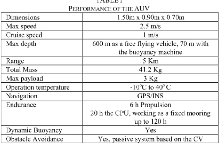
TABLEI PERFORMANCE OF THE AUV
Dimensions 1.50m x 0.90m x 0.70m
Max speed 2.5 m/s
Cruise speed 1 m/s
Max depth 600 m as a free flying vehicle, 70 m with the buoyancy machine
Range 5 Km
Total Mass 41.2 Kg
Max payload 3 Kg
Operation temperature -10oC to 40o C
Navigation GPS/INS
Endurance 6 h Propulsion
20 h the CPU, working as a fixed mooring up to 120 h
Dynamic Buoyancy Yes
Obstacle Avoidance Yes, passive system based on the CV
the 10:1 gearbox operate submerged in mineral oil to compensate external pressure. The maximum thrust force is 7.30 kg. The mathematical model used for the thruster is the Model 0: steady-state bollard-pull conditions.
T = ρar2η2 tan2(p) Ω|Ω| (1)
where T is axial thrust, ρ is the fluid density, a propeller
area, r radius of the propeller,ηefficiency of the thruster, p
pitch of the propeller and Ω propeller’s rotational velocity. This model fits very well to the dynamics of an underwater vehicle as long as does not exceed the speed of 2 knots [14].
Fig. 1. AUV mechanical layout.
B. Pressure housing design
cheap.
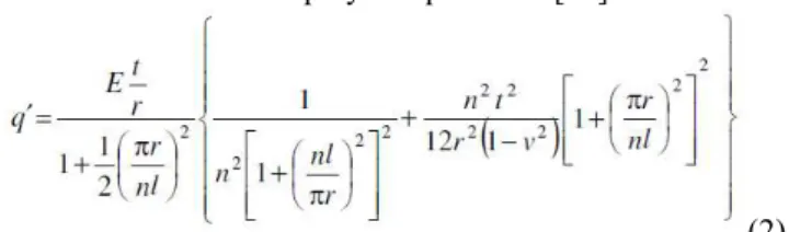
The general shape of the pressure housing is a circular transversal section with a length of 215.9 mm and an inner diameter of 95.25 mm. The aluminum alloy 6061-T6 has a Young’s, modulus of 69 GPA and Poisson’s ratio of 0.33 [15]. The Roark’s equations were utilized to determine the minimum wall thickness for 1000 m (10 MPa), the maximum operation depth is 600 m. Near to the Ecuadorian Antarctic Scientific Station the average depth in a radius of 5 Km is 450 m. The employed equation is [16]:
(2) where E is the modulus of elasticity, q´ is the maximum
working pressure, t is the wall thickness, r is the inner
radius, n is the number of lobes, v is the Poisson’s ratio and l the housing length. In order to confirm the results, a Finite
Element Analysis (FEA) was carried out using CATIA software, for the analysis parabolic elements were used because they presented more accurate results and suited better to a curved surface. The selected aluminum 6061-T6 tube has a thickness of 9,52 mm. These pressure housings carry the batteries and electronics. Similar FEA analysis was carried out for the pressure housing that carries the camera for to consider a polycarbonate window of 10 mm.
III. ELECTRONICS
The vehicle is powered by a set of four Lithium-Polymer battery of 25.9 V, 4500 mAh. Each battery is contained in an individual pressure housing located at the lower hull. The main element of the electronic system is the onboard computer inside of a FPGA in the development board TERASIC DE0 nano. The used resources of the development board are: FPGA, IDE connectors, 32MB SDRAM and 2Kb I2C EEPROM. The FPGA reads data from a set of kinematic sensors, cameras and radio frequency (RF) communication devices to generate guidance commands coded as PWM signals for to the ESC (Electronic Speed Controller) and the Gripper. The brushless motors and buoyancy machine are driven by the ESC with 50 Hz PWM signals; each ESC can drive currents up to 70 A. The ESC shares the space in the pressure housing with a Lithium-Polymer battery. The ESC transistors are in direct contact with the pressure housing wall through a heat sink thermal compound.
The kinematic sensors suite, for autonomous navigation purposes, includes a GPS Parallax (12 channels), an Inertial Measurement Unit (IMU) CH6 Robotics UM6 composed by 3 axis accelerometer, gyroscope and magnetometer and a set of three 5 Mega Pixels TERASIC cameras D5M. The communication devices are a RF 900 MHz XBee with range up to 50 Km and an Iridium 9602 SBD Satellite transceiver. The commands for the AUV are sent from a PC connected to the XBee modem or through the Iridium satellite link. The wireless communications are available when the vehicle is on the sea surface. The IMU connection port, GPS, XBee and Iridium modem are mounted on a daughter card
connected to a 40 pin IDE connector of the development board. The payload is a set of environmental sensors: temperature, conductivity, turbidity, pH and Dissolved Oxygen (DO). The AUV includes a Fiber Optic DO sensor embedded in the lower hull. All data from sensors, cameras and modems are stored in a set of 16 GB SD card connected to the FPGA. The FPGA, kinematic sensors, communication devices and SD cards are contained in a pressure housing located at the upper hull. The antennas are stored in filled mineral oil housing.
A. Camera System
The D5M cameras were modified to be store in a pressure housing with 50 mm of diameter. One end cap of these pressure housing has a 10 mm window made with optical polycarbonate. Additionally, two HD cameras with 60 fps were installed to obtain high quality underwater images using the same pressure housings. The D5M cameras are used for the CV system. The cameras are divided in two arrays: locking-down array installed in the lower hull and locking-forward array installed in the upper hull. Both groups are installed at the bow of the AUV and have an illumination system formed by high brightness LEDs. The locking-down array is composed by two D5M, rigidly fixed to each other with a known horizontal displacement between it and one HD camera. The transversal camera axis is inclined 45o locking to the sea bed. The locking-down array is part of the hardware components of the FPGA-based CV stereo system to detect biological samples and determinate its 3D coordinates to collect it then with a gripper. The locking-forward array is composed by a D5M and one HD cameras, locking to the water column. Table II resumes the array of cameras.
TABLEII ARRAY OF CAMERAS
Group Location Function Type
Locking-Down Array
Lower hull Locking sea bed, stereo vision for biological sampling collection.
2 D5M 1 HD
Locking-forward Array
Upper hull Locking water column, fish tracking. 1 D5M
1 HD
B. Fiber Optic Dissolved Oxygen Sensor.
maximum operational depth is 70 m. The reflectance input terminals are embedded in a hull penetrator. An instrumentation operational amplifier is used for photodiode signal pre-processing. Fig. 2 shows the Fiber Optic DO layout.
Fig. 2. Fiber Optic Dissolved Oxygen Sensor Scheme.
IV. SOFTWARE
The software runs on an FPGA Altera Cyclone IV EP4CE22F17C6N, running at 50 MHz. The software is divided in three layers:
Low layer: communications protocols, external memory RAM managing, Fiber Optic DO DSP, data storage and generation of control signals. Mid layer: GNC and CV.
Upper layer: Mission Manager.
The Low layer and Mid layer were implement using hardware description language VHDL to achieve real time processing. The Upper layer was implemented in a Nios II soft core processor. This layer is continuously updated based on realized missions at sea. The Low layer implements communication protocols for the sensors, manage of SD memory cards where data from scientific payload is stored and generates control signals to the thrusters. The sensors have an associated communication protocol, example: the IMU uses SPI and the GPS uses NMEA 0183. Each communication protocol was implemented by a VHDL block. The decoded sensor data is stored in a FPGA 16 bits words embedded RAM formed by M9K Embedded Memory Blocks. Also the decoded sensor data is stored in a set of SD cards by a dedicated VHDL block that reads the content of the FPGA embedded memory RAM and store it in a SD card, this block also can read the content of the SD cards, specifically Nautical Charts. A VHDL block implements the communication protocol of the D5M cameras and stores the images in an external 32 MB SDRAM. The overall system sampling time is 20 ms. The communication routines with the RF XBee devices are divided in two modules for transmission and reception tasks respectively. The transmitter VHDL block reads the content of the FPGA embedded RAM after the update process and a state vector from the Mission Manager then generates an encrypted data frame with a checksum. The VHDL module receiver processes a data frame from a PC and store it in an external non-volatile memory 2Kb I2C EEPROM. The data frame is encrypted and contains commands from the operator such as update mission profile or return to base command. The VHDL block that drives the Iridium 9602 SBD Satellite transceiver is controlled directly by the
Mission Manager, store the received data in the I2C EEPROM. The communications are managed directly by the Mission Manager. A dedicated VHDL block implements frequency domain algorithms for the Fiber Optic DO sensor, this block doesn’t work in real time. The algorithm requires some seconds to generate an accurate measure of DO from the water column. A VHDL block generates a 50 Hz PWM control signal for the ESC and gripper servo with 8 bits of resolution with a duty cycle that changes between 1500 µs and 1900 µs. Fig. 3 shows the software architecture.
Fig. 3. Software Architecture.
The Mid Layer is formed by a set of VHDL blocks that implement logic and mathematical operations for GNC and CV tasks. The mathematical operations are based on IEEE 754 32-bit floating point arithmetic. The trigonometric functions are implemented by floating-point CORDIC algorithm [18]. All algorithms were simulated with ModelSim to avoid overflows and singularity points. Implementation was done using logic operators and states machines to achieve processing time below 20 ms. This ensures real time capability for unmanned vehicles applications and reduce the number of FPGA logic elements.
The vehicle uses a classical GNC architecture. The function of guidance system is to determine the reference coordinates where the vehicle has to go. We used a fairly simple algorithm called "Line of Sight" that generates the reference yaw angle [19]:
) ,
( 2
arctan ref est ref est
ref y y x x
(3)controllers are implemented by the discrete equation type A [21].
The CV system is divided in two components: a dedicated VHDL block that implements a stereo vision system locking to the sea bed and a VHDL block for fish pattern recognition and tracking. Firstly, the CV algorithms were implemented by C and OpenCV library. After the verification of CV algorithms performance, they were implemented by VHDL code. Some common CV functions like Canny, used to detect edges were implemented using VHDL [22].
The stereo vision system is based on a classic technique where several 2D images of the same scene taken from different viewpoint are processing to establish correspondences between parts of the images to extract 3D depth information from the scene using triangulation [23]. The basic algorithm of the stereo vision system is:
1. Transform RGB incoming images from both D5M cameras to gray scale images.
2. Apply Gaussian filter and Canny to detect contours.
3. Filter objects size by contour lengths.
4. Find convex hull and convexity defects of the objects.
5. Detect and identify starfish by the convexity defects.
6. Calculate center of mass of identified starfish. 7. With the calculated center of mass of both images
apply triangulation to get the 3D position relative to the INS reference frame.
The algorithm for detect and tracking fish in the water column is:
1. Transform RGB incoming images from the single D5M camera to gray scale images.
2. Apply Gaussian filter and Canny to detect contours.
3. Apply clusterization by K-means function to separates the fish head and tail.
4. Find convex hull and convexity defects of the head and tail.
5. Detect and identify fish by convexity defects of the head and tail.
6. Calculate center of mass of identified fish and apply Kalman filtering techniques to track the fish. A secondary role of this VHDL block is to detect ices formation at the sea surface.
The Upper layer implements the Mission Manager, runs in a soft core 32 bits embedded processor Nios II. The Mission Manager is described with C language. The embedded processor was generated by the tool SOPC Builder. The Nios II communicate with the VHDL blocks from the Mid Layer through the Avalon bus. The Mission manager operates in a RF communications denied environment, so it must take decisions without human intervention based on predefined survivability techniques. The Mission Manager receives information from GNC, CV, SD card memory where a Nautical Chart is stored, XBee and Iridium communications. Based on the available information and using Bayesian Networks the Mission Manager generates the reference geographical position for the GNC and vehicle behavior. The Mission Manager performs an auto-test of overall system before the mission.
The Bayesian Networks helps to detect and isolate bugs that may be involves software or/and hardware [24]. The Mission Manager has the capacity to filter spurious information from ill-equipment.
V. RESULTS
The total time to compute an update state vector by the VHDL hardware was less than 18 ms. Hardware Resource Consumption of the DE0 nano FPGA development board was 90 % of FPGA´s logic elements, 3 PLL, 8 embedded multipliers, 3210 bits of embedded memory, SDRAM and EEPROM memories devices and 24 pins of the IDE port. The propulsion system was tested in steady-state bollard-pull conditions to measure its thrust with a load cell connected to a data acquisition board that works with MATLAB/ SIMULINK to estimate the constants of the mathematical model described in (1). The fiber optic DO was tested in laboratory comparing its lecture against calibrated laboratory grade equipment. The pressure housing was tested directly in the water column using a fishing line. The pressure housing was tested up to 650 m with minimal sea water filtration through the O-rings. The first sea trials were carried out at Ecuadorian waters, 5 Nautical Miles from the shore, at the coordinates 1°58'55.22"S, 80°45'18.79"W. During the sea trials were tested the performance of the INS and CV, RF and satellite communications. The INS error was 5% of distance after one hour since last GPS update. After the first sea trials the AUV was fully equipped with underwater cameras and environmental sensors to carry out a Census of Marine Life, looking for starfish to collect then with the gripper, identifying and tracking fish. Fig. 4 shows the sea trials at Ecuadorian waters.
Fig. 4. a) AUV sea trials at Ecuadorian waters, b) Tracking fish.
The AUV was deployed at Antarctica during the Ecuadorian Summer Antarctic Expeditions 2011 and 2012. The CAML tasks for the AUV in order of priority were:
Identify and track fish in the water column. Identify and collect starfish from the sea bed
with the gripper.
Follow a path and land on predefined sites of the sea bed using the buoyancy machine.
Take samples of sediments from the sea bed using the gripper and a bag.
Antarctic waters between 6 m and 550 m [25].
Fig. 5. AUV sea trials at Antarctica: a) Vehicle deployment from the shore, b) Detecting starfish on the sea bed.
The AUV was capable to detect and collect some starfish, however the successful rate was low. Sometimes the AUV return to the surface with rocks instead of starfish, the probability to detect and collect a starfish was less than 10 %. The collected starfish is shown at Fig. 6 b). Through the lecture of fiber optic DO were established sites where the sediment would contain biological organisms. Using this data, sediment samples were collected by the Gripper. Fig. 6 c) shows a collected sediment sample.
Fig. 6. AUV’s sampling results at Antarctica: a) tracking an Antarctic fish, b) collected starfish, c) sediment sample.
VI. CONCLUSIONS AND FUTURE WORKS
This paper presented the design and construction of an Autonomous Underwater Vehicle that carried out successful missions at Ecuadorian waters and Antarctica, taking underwater images and collecting biological samples fully autonomously. The FPGA accomplished the required computational resources demanded by the GNC and CV algorithms using 32 bits floating point arithmetic, CORDIC algorithms and Nios II embedded processor. Future works includes hydrodynamics optimization, improvement of the CV using active contours method and the development a 6 DoF robotic arm to collect biological samples from the sea bed.
REFERENCES
[1] De Broyer C, Danis B, eds (2010) SCAR-MarBIN: The Antarctic Marine Biodiversity Information Network. World Wide Web electronic publication. Available online at the SCAR-MarBIN website
http://www.scarmarbin.be/.
[2] C. Summerhayes, "AUV in the Context of Global Climate Change," Proceedings of the International Workshop on Autonomous Underwater Vehicle Science in Extreme Environments held at the Scott Polar Research Institute, Cambridge, 11-13 April 2007. London: Society for Underwater Technology, pp. 8-9.
[3] J Mastro and J Bozanic. "Antarctic Scientific Diving Manual". Antarctic Support Associates for National Science Foundation, 1994. [4] Y. Chardard, T. Copros, " Swimmer: final sea demonstration of this
innovative hybrid AUV/ROV system," in Underwater Technology, 2002. Proceedings of the 2002 International Symposium, Volume 1, Issue, 2002 Page(s): 17 – 23.
[5] T. Aoki, T Murashima, S Tsukioka, H. Nakajyoh, M. Ida, " Development of deep sea free swimming ROV “UROV7K”," in OCEANS apos; 99 MTS/IEEE. Riding the Crest into the 21st Century, Volume 3, Issue, 1999 Page(s): 1307 – 1311.
[6] B. Butler. “Field trials of the Theseus AUV”. Proc. Int. Symp. on Unmanned Untethered Submersible Technology, page 615, 1995. [7] R. Fauzi, D. Salazar, R. Kadzim, L. Burbano, A. Hussin. "Geographic
information system Mapping in Pedro Vicente Maldonado ecuadorian scientific station antarctica Base (Greenwich island) antarctic Peninsular". ASM Science Journal, Volume 3(2), 2009.
[8] M. Marinoni, T. Facchinetti, G. Buttazzo, G. Franchino. "An Embedded Real-Time System for Autonomous Flight Control". Proceedings of the 2006 ANIPLA International Congress on Methodologies for Emerging Technologies in Automation (ANIPLA). [9] R. Amin, A. Khayyat, K. Osgouie. "Neural networks control of autonomous underwater vehicle". Mechanical and Electronics Engineering (ICMEE), 2010 2nd International Conference on Volume 2.
[10] Y. Liu, Q. Dai. "Vision aided unmanned aerial vehicle autonomy: An overview". Image and Signal Processing (CISP), 2010 3rd International Congress on Volume 1.
[11] V. Maxim, K. Zidekb. "Design of High Performance Multimedia Control System for UAV/UGV Based on SoC/FPGA Core". Modeling of Mechanical and Mechatronics Systems. Procedia Engineering Volume 48 (2012) 402–408.
[12] J. Olivares, J. Gómez, J. Palomares, M. Montijano. "Biprocessor SoC in an FPGA for Teaching Purposes ". ICALT 2008. Eighth IEEE International Conference on Advanced Learning Technologies. [13] N. Cruz, A. Matos, R. Almeida, B. Ferreira. "TriMARES - A hybrid
AUV/ROV for dam inspection". OCEANS 2011.
[14] L. Whitcomb, D. Yoerger, "Preliminary Experiments in the Dynamical Control of Marine Thrusters Part 1: Dynamical Modeling," Submited for review to IEEE Journal of Oceanic Engineering, February 1996.
[15] G. Murray. "Handbook of Material Selection for Engineering Application" Marcel Dekke, Inc. 1997.
[16] W. Young, R. Budynas. "Roark’s Formulas for Stress and Strain". McGraw-Hill. 2002.
[17] P. Jorge, P. Caldas, C. Rosa, A. Oliva, J. Santos. "Optical fiber probes for fluorescence based oxygen sensing" Sensors and Actuators B: Chemical, Volume 103, Issues 1–2, 29 September 2004, Pages 290– 299.
[18] N. Neji, A. Boudabous, W. Kharrat, N. Masmoudi. "Architecture and FPGA implementation of the CORDIC algorithm for fingerprints recognition systems". 2011 8th International Multi-Conference on Systems, Signals and Devices (SSD).
[19] M. Caccia, “Preliminary sea trials of SESAMO: An autonomous surface vessel for the study of the air-sea interface,” CNR-ISSIA Sez. Di Genova, Tech. Rep. Rob-04-SESAMO pt, 2004.
[20] G. Welch and G. Bishop, “An introduction to the kalman filter,” In Computer Graphics, Annual Conference on Computer Graphics & Interactive Techniques. ACM Press, Addison-Wesley, Los Angeles, CA, USA, SIGGRAPH 2001 course pack edition, course No. 8, Aug 12-17 2001.
[21] G. Szafranski, R. Czyba. "Different Approaches of PID Control UAV Type Quadrotor". Proceedings of the International Micro Air Vehicles conference 2011 summer edition
[22] P. Pankiewicz, W. Powiertowski, G. Roszak. "VHDL implementation of the lane detection algorithm". 5th International Conference on Mixed Design of Integrated Circuits and Systems, 2008. MIXDES 2008.
[23] C. Cuadrado, A. Zuloaga, J. Martin, J. Laizaro. "Real-Time Stereo Vision Processing System in a FPGA". IECON 2006 - 32nd Annual Conference on IEEE Industrial Electronics.
[24] O. Mengshoel, A. Darwiche, S. Uckun. "Sensor validation using Bayesian networks". In Proceedings of the 9th International Symposium on Artificial Intelligence, Robotics, and Automation in Space (iSAIRAS-08), 2008.