EXTRACTION OF THE 3D FREE SPACE FROM BUILDING MODELS FOR INDOOR
NAVIGATION
Abdoulaye A. Diakit´ea,∗, Sisi Zlatanovaa
a
3D GeoInformation, Department of Urbanism, Delft University of Technology, Jaffalaan 9, 2628 BX Delft, The Netherlands - (a.a.diakite, s.zlatanova)@tudelft.nl
KEY WORDS:3D Indoor Navigation, Free Space Extraction, Navigable Space, IFC, CityGML, IndoorGML
ABSTRACT:
For several decades, indoor navigation has been exclusively investigated in a 2D perspective, based on floor plans, projection and other 2D representations of buildings. Nevertheless, 3D representations are closer to our reality and offer a more intuitive description of the space configuration. Thanks to recent advances in 3D modelling, 3D navigation is timidly but increasingly gaining in interest through the indoor applications. But, because the structure of indoor environment is often more complex than outdoor, very simplified models are used and obstacles are not considered for indoor navigation leading to limited possibilities in complex buildings. In this paper we consider the entire configuration of the indoor environment in 3D and introduce a method to extract from it the actual navigable space as a network of connected 3D spaces (volumes). We describe how to construct such 3D free spaces from semantically rich and furnished IFC models. The approach combines the geometric, the topological and the semantic information available in a 3D model to isolate the free space from the rest of the components. Furthermore, the extraction of such navigable spaces in building models lacking of semantic information is also considered. A data structure named combinatorial maps is used to support the operations required by the process while preserving the topological and semantic information of the input models.
1. INTRODUCTION
3D modelling of buildings and cities have been occupying a cen-tral position in BIM and GIS research for more than a decade. The construction industry as well as the municipalities quickly understood the huge potential behind such 3D models and con-tributed to boost the researches in the topic. Indeed, 3D models open wide access to several useful applications such as building analysis, planning, management and several simulation processes (energy consumption, light exposure, network coverage, natural disaster estimation, etc.). It has been already proven that 3D mod-els are the future of building and cities representation.
Few standards arise along from both BIM and GIS fields in or-der to offer a convenient structuring of the 3D representations of buildings. The most renown ones on both sides are semantic-oriented and are the Industry Foundation Classes (IFC) from (Build-ing SMART International, 2013) for BIM and the City Geogra-phy Markup Language (CityGML) from (Open Geospatial Con-sortium, 2012) for GIS. Research fields such as indoor naviga-tion and localizanaviga-tion have a clear interest in such 3D representa-tions and standards to support critical tasks like emergency re-sponse or simply efficient facility management (Isikdag et al., 2013, Costin and Teizer, 2014). A dedicated standard named In-doorGML (OGC et al., 2015) has been even introduced to support and promote indoor navigation using 3D models.
Thereby, semantically rich models can now make the difference for indoor navigation. However, while the benefit of the topolog-ical and semantic information provided by such models is clearly recognized, there is still a huge lack in exploiting the geomet-ric data for the spatial description of the environment to navigate through. This can be explained by many reasons. First of all, most of the research regarding indoor navigation is application-specific and mostly dedicated to rolling robots and pedestrians (Zlatanova et al., 2014). Thus, focus on walkable areas is made in such studies and 2D floor plans or 2.5D representations connect-ing several 2D floor levels (via the stairs or elevators) are often
∗Corresponding author
sufficient. Secondly, in most of the cases, the elements populat-ing the indoor environment such as furnitures and other objects are neglected in favor of the structural elements such as walls, floors and openings. So the final models are highly simplified and represent the buildings as simple sets of rooms, corridors and halls. Finally, the complexity involved in a full 3D representation of the navigation space is an important daunting factor. Indeed, that complexity makes it tempting to keep on projecting 3D data into 2D spaces to simply rely on the well known 2D approaches for navigation.
In this paper, we face the previously described restrictions and discuss a new paradigm, that consists of performing the indoor navigation in a full 3D model. For that purpose, we introduce an approach allowing to extract the free space that should be dedi-cated to navigation, starting from a BIM model with a furnished indoor environment. Thanks to its precise spatial and semantic description, our system can support pedestrians (disabled or not) and robots, as well as flying objects like drones, that encountered a huge popularity in the few recent years. A simplified represen-tation, corresponding to a minimal bounding box is provided to the furnitures and others indoor objects, allowing to considerably reduce their geometric complexity. We illustrate the great advan-tages of full 3D indoor navigation and provide a motivation why such a system should take over traditional approaches.
In Section 2, we discuss the researches related to 3D spatial rep-resentation for indoor navigation. The details of our approach are presented in Section 3, while Section 4 illustrates the results of the tests on several IFC and 3D CAD models and discusses their future improvement, before we conclude the paper.
2. RELATED WORK
model or a grid), guidance (Points of Interest, Landmarks), guid-ance (visualisation) of the path and finally tracking/correction (if the path is not followed). While precise indoor positioning is still an extensive research topic (Liu et al., 2007, Adler et al., 2015), the research regarding 3D indoor navigation focusses mainly on the path computation (Musliman et al., 2008) or tries to conceptu-ally address the requirements for such way of navigating. There-fore, only few addresses the modelling aspect. We organize the study of the close works following those three categories (con-cepts, graph extraction and modelling).
Several concepts have been investigated to support indoor navi-gation in 3D. The main research question they address is the or-ganization of the indoor environment, known to be very complex. (Meijers et al., 2005) discussed the structuring of the interior and introduced a semantic model to assist evacuation task on 3D mod-els. The issue of subdividing the indoor space into functional spaces to allow advanced navigation is developed in (Zlatanova et al., 2013) and (Kr¯uminait˙e and Zlatanova, 2014). The authors emphasize the importance of a 3D description of the space and the necessity to rely on semantic information for efficient systems. (Becker et al., 2009) introduced a conceptual framework aiming to bridge the gap between representation models for route plan-ning and indoor localization, as the two have different points of interest. The authors proposed a multilayered space-event model to allow both to be performed on a same 3D model. The model can be used to define subdivision of building space according to user profile (walking, driving), security or property regulations.
Semantically rich BIM and GIS models provide suitable informa-tion to automatically extract navigainforma-tion graphs. Since the latter requires an organization of the indoor space in several space units (rooms) and the spatial relationships between them, those infor-mation are offered by the models and can be directly exploited. Thus several works study this extraction on IFC models (Lin et al., 2013, Boysen et al., 2014), or CityGML LoD4 models (Liu and Zlatanova, 2013) for deriving paths for multi locomotion type (Khan et al., 2014) or support emergency response (Boguslawski et al., 2015). Even though the 3D models were considered in those works, they were used at a very simplified level, consider-ing the indoor spaces as empty boxes and ignorconsider-ing the furnitures and other obstacles.
Recognizing the complexity of how the indoor space can be or-ganized, very few researches investigated possibilities to model it in 3D while considering accessible areas for a moving subject. Thereby, (Yuan and Schneider, 2010) introduced a LEGO-based 3D representation allowing to consider users widths, heights and particular tasks like avoiding stairs for example. Their model approximates the obstacles and provides a connectivity graph to ease the navigation extraction.
Closer work can be also found in the computer vision field, where few approaches addressed the issue of recovering the indoor free space available for navigation from single images (Hedau et al., 2009, Gupta et al., 2011, Hedau et al., 2012). The goal is to geo-metrically estimate the objects populating the indoor scenes and recover their spatial layout to determine the space that is really accessible for navigating robots for example.
Therefore, despite the consensus in recognizing the necessity to move toward 3D representation of the indoor space, there is, to our knowledge, no approach considering the navigable space as it really is in semantically rich 3D models for indoor navigation purpose. We present in the following section our method allow-ing to consider the indoor 3D space and its furnitures, and to ex-tract the actual free navigable space it contains, while preserving the topological and semantic information of the original models.
3. FRAMEWORK AND PRELIMINARY NOTIONS
More and more buildings have highly detailed 3D model of their entire structure, as well as their facilities. We present in this section the workflows leading to the extraction of the navigable space in a building model, depending on its input type, either IFC or 3D CAD. We also briefly present the combinatorial maps data structure that is used all along the process.
3.1 Workflows based on the input models
We present here two approaches. The first one considers IFC models of furnished buildings and automatically extracts the spaces of interest to support elaborated indoor navigation. On the other hand, several buildings do not possess semantically rich mod-els, but just geometric description in form of 3D CAD models of their interior. Thus the second approach allows to extract the free spaces in such type of geometric models. In the case of an IFC input model, the four steps leading to the extraction of the free space are the following:
• Parsing of the spaces described by theIfcSpaceobjects in the model;
• Detection and simplification of the furnitures inside the Ifc-Spaces, described by theIfcFurnishingElements;
• Boolean operations between eachIfcSpaceand its contained (and simplified)IfcFurnishingElements;
• Detection of the openings (IfcDoorsandIfcWindows) sur-rounding the original IfcSpacesand topologically linking them to the extracted free space volumes.
On 3D CAD models, we assume that the model has only geo-metric information available, thus correspond to a set of unstruc-tured polygons. The approach to extract the free navigable space from such models rely on the method described by (Diakit´e et al., 2014a) and is summarized by the four following steps:
• Reconstruction of the spatial relationships between the poly-gons to obtain closed volumes;
• Recovering of the spatial relationships between the recon-structed volumes;
• Extraction of the air volumes contained inside the model (that correspond to the free space);
• Automatic semantic labelling of the volumes based on heuris-tic rules combining the geometric and recovered topological information.
Indeed, in the case of the 3D CAD, even though the volumes corresponding to the free spaces are extracted at the third step, they are not yet semantically identified. Thus, the last step is essential for the output volumes. More details on both processes for IFC and 3D CAD are presented in the following sections.
3.2 Combinatorial Maps as Supporting Data Structure
relationships between them. A dart corresponds to a part of an oriented edge, plus a part of all the incident cells. An(i+ 1) -cell is constructed byi-sewing the darts of a set ofi-cell with the βilink through their proper(i−1)-cells. For example, a2-cell
(or face) is built by1-sewing a set of1-cells (or edges), to link them byβ1 through their common0-cells (vertices). The darts
and theβrelations allow an-map to represent the relationships between all the cells it contains. In addition to this, an-map al-lows to associate attributes (that can be any type of information) to any cell. This property is used in a3-map to associate to each 0-cells the given3D coordinates of a point inR3 to produce a so-called linear cell complex (LCC). But this can also be used to store information such as semantic.
Thanks to all those properties, a3-map has been used in several works as a suitable data structure to represent 3D building mod-els (Horna et al., 2015). Indeed, the subdivision of objects in volumes (3-cells), faces, edges and vertices that it provides fits well to the description of a building model. On the other hand, it allows to perform operations on models while preserving their topological and semantic information, which is a helpful skill. Furthermore, the ability of the data structure to gather geome-try, semantic and topology, with the possibility to derive the dual space, makes our approach fit to the IndoorGML standard.
To be able to perform the free space extraction operations on the building model, the interesting volumes are then first recon-structed as3-cells of a LCC. For simplicity, we will refer to the model in built as a Free Space LCC (FS-LCC). We detail in the following section the entire process for BIM and CAD models.
4. FREE SPACE EXTRACTION ON IFC MODELS
IFC is a well suited standard for applications like indoor naviga-tion. It provides the description of the indoor spaces thanks to itsIfCSpaceclass. AnIfcSpaceintuitively corresponds to a vol-ume bounding a space contained in the building. The common practice to build it is following the layout of the indoor structural elements (e.g. walls, floors, ceilings and openings). Neverthe-less, there are clearly some ambiguities in the wayIfcSpacesare built in a model, since depending on the bounding construction elements, they can span over multiple physical spaces for exam-ple. But this is not a limitation in this work and we assume that the input IFC model already contains the information of the Ifc-Spaces.
(a) (b)
Figure 1: OriginalIfcSpacesin an IFC model. (a) One building storey. (b) CorrespondingIfcSpaces.
Figure 1 illustrates the structural elements of a storey of a build-ing model (from (Amor, 2012)) and theIfcSpacesavailable in the model for that storey. It can be seen on Fig. 1(b) that they correspond to the rooms of the storey. Having this information, in addition to the link between the spaces and the openings or the other neighbouring spaces, one can directly derive a naviga-tion graph by considering eachIfcSpace as a single node. But
in reality, not all the space bounded by anIfcSpaceis navigable, because of the presence of furnitures and other objects that stand as obstacles (Fig.2).
(a) (b)
Figure 2:IfcSpacethat includes the furnitures. (a) Original IFC model. (b) Corresponding FS-LCC (with twoIfcSpacesrendered in wireframe).
Thus, extracting the real navigable space in such model amounts to exclude the space occupied by the obstacles inside the rooms. For this purpose, we proceed to the construction of the FS-LCC for which the first3-cells correspond to theIfcSpacesof the input model. This is done by collecting all the polygons of a given Ifc-Space, recreating them as2-cells of the FS-LCC and then linking them byβ2, through their common edges. Figure 2(b) illustrates
a3-map representation of the spaces and furnitures of Fig.2(a). The semantic information of those elements can be directly trans-ferred to their corresponding3-cells that will keep them for the rest of the process. Now that we have the spaces, let’s consider the furnitures inside.
4.1 Simplification of the Objects inside theIfcSpaces
Furnitures in the IFC standard are described by the IfcFurnishin-gElementclass. They can independently be simple objects with relatively simple geometries or they can be complex objects com-posed of several components with complex geometries. Such complex representations are very useful in the context of realistic visualization but since generally only their visual aspect matters, they often embed several topological errors (open volumes, float-ing components, degenerate geometries, etc). Such errors would lead to invalid cells in the FS-LCC. We therefore perform a sim-plification of the furnitures to avoid geometrical issues and at the same time to reduce the complexity of the output navigable space. It is not a necessary task in the process, but it is used here to test the approach.
Figure 3: Example of living room furnitures.
An intuitive solution to the simplification problem is the usage of the minimal bounding box method. It is widely used in computer graphics, mainly for ray-tracing, intersection checking, but also in robotics (Bergen, 1997, Huebner et al., 2008). Several differ-ent approaches can lead to a minimal bounding box depending on the constraints considered. In this paper we used the aligned axis bounding box (AABB) approach as the furnitures of our model test set are mostly axis aligned1. Nevertheless, an oriented bound-ing box approach is more suitable to obtain minimal boxes inde-pendently of the orientations of the objects to simplify.
(a) (b) (c)
Figure 4: Simplification of a furniture. (a) Original geometry in the IFC. (b) Corresponding bounding box of the furniture. (c) Simplified geometry of the furniture.
Figure 4 shows the AABB simplification of a table. It is a typi-cal example showing that there are still free space encompassed by the simplification. In this case it is mainly the space below the table (see Fig.4(b)). But considering the entire space around the furnitures comes back to rely on their original geometry, that would considerably complicate the resulting extracted free space. Thus, for all the detected furnitures in the IFC, their equivalent bounding boxes3-cells are created in the FS-LCC to replace them (see Fig.5).
(a) (b)
Figure 5: FS-LCC that includes the furnitures. (a) The original geometries of the furnitures. (b) Their simplified boxes.
4.2 Subtraction of the Furnitures from the IfcSpaces
Once the furnitures are simplified, the following step consists in removing the space occupied by the furnitures from the3-cells of theIfcSpacescontaining them. As specified previously, the IFC file must contain the geometric description of the IfcSpacesin addition to the spatial relationships that describe the link between the spaces and their surrounding elements.
Figure 6: Relationships betweenIfcSpaceand the elements con-tained in it.
The IFC classIfcRelContainedInSpatialStructureallows to make the link between the container and the contained elements (Fig.6).
1
Aligned against the euclidean axis.
Indeed, theContainsElementsattribute of a givenIfcSpaceallows to retrieve which furnitures are contained in it. The latter are de-scribed by theIfcProductclass, and are not the only elements that can be contained by the spaces (IfcCovering, ...). Inversely, the IfcSpacecontaining a givenIfcProductcan be retrieved through theRelatedElementsattribute of the latter.
(a) (b) (c)
Figure 7: (a) Actual free space3-cell of a room with (b) wire-frame and (c) bottom-up views.
The final3-cells describing the actual navigable space are finally obtained by performing successive boolean operations between the initials3-cells of theIfcSpacesand the3-cells of the simpli-fiedIfcProductsthat they contain. Figure 7 illustrates the result-ing3-cell for the example of the room of Fig.5. The view offered by Fig.7(c) allows to see the carve produced by the boolean oper-ations. More results on IFC models are presented and discussed in the next section.
4.3 Linking the Spaces and the Openings
The Openings, that correspond toIfcDoorsandIfcWindows, are crucial features that should necessarily be considered in our pro-cess. They constitute critical elements in any navigation process because they are the links between different spaces of the indoor environment. Therefore, they have to be integrated to the FS-LCC.
(a) (b)
Figure 8: Example ofIfcDoorsandIfcWindows.
Similarly toIfcFurnitures, theIfcDoorsandIfcWindowsare often composed by multiple geometry objects, as illustrated by Fig.8. Nevetheless, one particularity of the IFC standard is the definition of the void space where the doors or windows should be placed in other structural elements (e.g. walls). Thus, while dealing with an IFC model, one may need to cut the space required for a door or a window out of the receiving element before placing it in there. Such void spaces are represented by the classIfcOpeningElement, and can be reached from anIfcDoororIfcWindowthrough their FillsVoidattribute.
We therefore use the void volumes directly as simplified version of the openings for their integration in the FS-LCC (see Fig.9(a)). As the spatial relationships between the openings and the free spaces volumes are important, theβ3relations between them are
(a) (b)
Figure 9: A3-cell of the FS-LCC with its surrounding openings. (a)3-cells of the openings. (b) Contact surfaces of the openings on the free space.
In some particular cases, a wall separating two spaces can be de-signed with a hole but without anIfcOpeningElement. In that case it should be checked if theIfcSpacesfrom both sides touch each other. If not, the link between the spaces can still be found through the wall, at the level of the IFC model.
5. FREE SPACE EXTRACTION ON 3D CAD MODELS
By 3D CAD models, we refer in this section to 3D Models of building that contains only geometric information and cannot be considered as BIM models due to their lack of topological and semantic information. Such type of model are quite numerous in the market as they are basically convenient for visualization purpose, thereby the most produced type of 3D models before the event of the BIM in the past decade.
In (Diakit´e et al., 2014a), a method allowing to enrich such geo-metric models with topology and semantic is introduced. The ap-proach relies on the formalism of the3-maps to recover the topo-logical relationships between the set of unstructured polygons of the input data, leading to the shape reconstruction of the building components. Furthermore, the geometric and reconstructed topo-logical relationships between the components are combined and used to define a set of heuristic rules and perform the semantic labelling of the structural components in a propagation scheme.
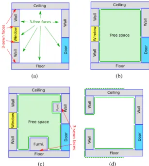
During the information enrichment process, the air volumes in-side the rooms of the building are automatically generated as3 -cells and are the first semantically identified components. Those air volumes exactly correspond to the free navigable space. Fig-ure 10 illustrates the process on a simple room example pro-jected on 2D for simplification purpose. Despite the fact that furnished building models are not discussed in the paper, the ap-proach can independently produce the3-cells of the free spaces (see Fig.10(c)). Furthermore it is possible to semantically con-sider the furnitures by adding simple heuristic rules (e.g. any 3-cell mainly surrounded by an air volume and other structural elements such as walls and/or floors can be considered as a furni-ture).
Nevertheless, due to the lack of information on the input models, more constraints has to be considered for this second approach. A first one is regarding the doors and windows of the input mod-els. They should be closed otherwise the spatial subdivision on which the topological reconstruction is based will not distinguish the outdoor from the indoor of a room or of the whole building (see Fig.10(d)). Such configuration will then lead to an infinite volume or a shell enveloping the entire model. A second con-straint concerns the complexity of the geometries of the furnitures and the openings. Indeed since complex objects often contain topological errors, the volume reconstruction cannot be properly performed, leading to generation of open volumes for example.
(a) (b)
(c) (d)
Figure 10: 2D projection of a free space volume reconstruction based on the approach of (Diakit´e et al., 2014a). (a) The faces that are not involved in a3-sew operation among the model are de-tected. (b) Those faces are duplicated and2-sewn between them to form a new volume corresponding to the free space. (c) The process works independently of the presence of other components in the scene. (d) In case of open window (or door), the free space volume cannot be closed.
6. RESULTS AND DISCUSSION
The entire framework presented in the previous sections have been implemented and tested. We present in this section the out-put results of few test models of type IFC obtained from the Open IFC repository (Amor, 2012) and self produced CAD model. The algorithms have been implemented in the C++11 language and is supported by several libraries:
• the Computational Geometry Algorithms Library (The CGAL Project, 2016) that provided several geometric algorithms as well as the implementation of then-map data structure; it was also used to perform the boolean operations (difference and union) using the Nef Polyhedron package;
• the Open Asset Import Library (Assimp Project, 2015) that provided readers/writers of several 3D model formats;
• and finally the IfcPlusPlus library (IfcPlusPlus, 2016) that provided a complete parser for IFC2x3 and IFC4 formats.
Also the BIMVision viewer (Datacomp, 2016) has been used for visualization and snapshots of the IFC models used in this paper.
6.1 Results of the free space extraction
Figure 11 illustrates the results of the process on four test models for which the specificities are detailed in Table 1. House, Du-plexandOfficeare IFC models, andCAD-housewas made using SketchUp Make (Trimble, 2016).
Models # storeys # spaces/rooms comp. time (s)
House 2 7 1.06
Duplex 2 25 1.276
Office 5 82 5.916
CAD-house 1 5 0.5
Table 1: Characteristics of the test models set of 3 IFC model and 1 CAD.
and efficiency of the approach allow to reach satisfying perfor-mances. As it can be seen in Table 1, the number of spaces/rooms directly affects the computation time of the process, although the latter stays low for all the models. The computation time was estimated on a Intel Core i7-2760QM laptop, with 2.40GHz x 4 CPU and 8Go of RAM. The middle columns of Fig.11 point out the difference between considering the space units as provided by the original models and considering the furnitures and other objects that they contain.
(a) (b)
Figure 12: Zoom on a free space3-cell from the CAD-house model. (a) Wireframe view showing the layout of the interior. (b) Plain view showing the concavity of the navigable space.
It clearly appears that the navigable space can be drastically re-duced depending on the configuration of the objects inside the building. On the other hand, the results also emphasize how com-plex the indoor environment can be and how challenging it can be to perform navigation, not only for pedestrian but for all possible type of movable subjects such as drones, robots, disabled peo-ple, etc, in indoor models. Figure 12 gives another perspective confirming this.
6.2 Discussion
An efficient indoor navigation system needs to be flexible, pre-cise and to offer a coherent description of the space in which the subject is supposed to circulate. It is only possible by consider-ing the real free space in 3D that a system can perform navigation independently from the moving subject, so that, e.g. the facility management service of a building and the fire brigade can rely on a same model for different purposes. The spatial representa-tion of the indoor navigable space proposed in this paper clearly makes it possible to go for a deeper exploitation of the space for finer navigation purpose.
The proposed algorithms are stable and can be robustly imple-mented with freely available libraries. The exact predicates ker-nel of CGAL allows to perform robust boolean operations and 3-map guarantees topologically valid3-cells outputs. Thanks to that, the produced3-cells of the free space are always watertight volumes.
Nevertheless, the results highly depend on the quality of the in-put model on which the process relies. Stability and topological validity cannot be insured for example in the case of floating ob-jects that has no contact with the surface boundary of the spaces
containing them. Similarly, the topological relationships cannot be maintained in the FS-LCC if there is no contact between the spaces and their surrounding elements.
Finally the simplification of the furnitures is making the vol-ume intersections less complex, helping to the stability of the approach. But for a finer recovering of the free space, the space surrounding the furnitures needs to be considered as well. Indeed the bounding box approach involve losses of spaces like below the tables or beds, that can be navigable area for domestic robots for example. Thus better approaches to simplify them need to be investigated.
7. CONCLUSION
We introduced a novel point of view that consists of representing the indoor building environment completely in 3D vector model for indoor navigation purpose. While the existing approaches use simplified representations of the space and ignore the ob-jects inside, we propose a method to extract the navigable space in such complex configuration to exactly know where a subject can navigate properly inside the building, considering his/its con-straints. Starting from a semantically rich model, the general spaces are first extracted and then the furnitures, replaced by sim-plified representations, are extracted from the global space thanks to boolean operations. A method to deal with geometric models like CAD is also proposed, and we performed several tests to val-idate the global workflow.
Several questions still need to be investigated and solved. The first one concerns the automatic extraction of a navigation graph on such a model. Navigation graphs rely on nodes represent-ing the accessible spaces and edges that stand for their adjacency links. To extract the nodes, convex cells are needed to ensure a position inside each cell. While this can still be solved by find-ing a random point in the3-cell of the free space, this brings out the question of the structuring of the indoor free space. A smart subdivision of the navigable space should be investigated so that navigation to point of interest inside the rooms can be possible (Zlatanova et al., 2013).
Another aspect that needs to be considered in future work is the dynamic changes that can occur in the scenes. Indeed, the fur-nitures represented in the models have different movability, that can affect the precision of the extracted free spaces. For exam-ple a chair is most likely to be moved than a cupboard or a desk. Thus our approach gets stronger in a less dynamic environment. But to be able to consider such aspect, more information on the semantic of the furnitures and moving objects will be required in the input models (e.g. dynamic weight on the furnitures).
ACKNOWLEDGEMENTS
This research is funded by the NWO/STW M4S project Smart 3D indoor models to support crisis management in large public buildings (www.sims3d.net).
REFERENCES
Adler, S., Schmitt, S., Wolter, K. and Kyas, M., 2015. A survey of experimental evaluation in indoor localization research. In: Indoor Positioning and Indoor Navigation (IPIN), 2015 Interna-tional Conference on, IEEE, pp. 1–10.
Assimp Project, 2015. Open Asset Import Library.
Becker, T., Nagel, C. and Kolbe, T. H., 2009. A multilayered space-event model for navigation in indoor spaces. In: 3D Geo-Information Sciences, Springer, pp. 61–77.
Bergen, G. v. d., 1997. Efficient collision detection of complex deformable models using aabb trees. Journal of Graphics Tools 2(4), pp. 1–13.
Boguslawski, P., Mahdjoubi, L., Zverovich, V., Fadli, F. and Barki, H., 2015. Bim-gis modelling in support of emergency re-sponse applications. Building Information Modelling (BIM) in Design, Construction and Operations149, pp. 381.
Boysen, M., de Haas, C., Lu, H. and Xie, X., 2014. A journey from ifc files to indoor navigation. In: Web and Wireless Geo-graphical Information Systems, Springer, pp. 148–165.
Building SMART International, 2013. Industry Foundation Classes (IFC), IFC4.
Costin, A. and Teizer, J., 2014. Utilizing bim for real-time visual-ization and indoor localvisual-ization of resources. Computing in Civil and Building Engineeringpp. 649–665.
Damiand, G. and Lienhardt, P., 2014. Combinatorial maps: effi-cient data structures for computer graphics and image processing. CRC Press.
Datacomp, 2016. BIMVision Freeware IFC Viewer.
Diakit´e, A. A., Damiand, G. and Gesquiere, G., 2014a. Au-tomatic semantic labelling of 3d buildings based on geomet-ric and topological information. In: Proc. of 9th Interna-tional 3DGeoInfo Conference (3DGeoInfo), Karlsruhe Institute of Technology.
Diakit´e, A. A., Damiand, G. and Van Maercke, D., 2014b. Topo-logical reconstruction of complex 3d buildings and automatic ex-traction of levels of detail. In: Eurographics workshop on ur-ban data modelling and visualisation, Eurographics Association, pp. 25–30.
Gupta, A., Satkin, S., Efros, A. A. and Hebert, M., 2011. From 3d scene geometry to human workspace. In: Computer Vision and Pattern Recognition (CVPR), 2011 IEEE Conference on, IEEE, pp. 1961–1968.
Hedau, V., Hoiem, D. and Forsyth, D., 2009. Recovering the spa-tial layout of cluttered rooms. In: Computer vision, 2009 IEEE 12th international conference on, IEEE, pp. 1849–1856.
Hedau, V., Hoiem, D. and Forsyth, D., 2012. Recovering free space of indoor scenes from a single image. In: Computer Vi-sion and Pattern Recognition (CVPR), 2012 IEEE Conference on, IEEE, pp. 2807–2814.
Horna, S., Damiand, G., Diakit´e, A. A. and Meneveaux, D., 2015. Combining geometry, topology and semantics for generic build-ing description and simulations. In: Eurographics Workshop on Urban Data Modelling and Visualisation, The Eurographics As-sociation, pp. 13–18.
Huebner, K., Ruthotto, S. and Kragic, D., 2008. Minimum vol-ume bounding box decomposition for shape approximation in robot grasping.In: Robotics and Automation, 2008. ICRA 2008. IEEE International Conference on, IEEE, pp. 1628–1633.
IfcPlusPlus, 2016. Ifc++ Open C++ IFC library.
Isikdag, U., Zlatanova, S. and Underwood, J., 2013. A bim-oriented model for supporting indoor navigation requirements. Computers, Environment and Urban Systems41, pp. 112–123.
Khan, A. A., Donaubauer, A. and Kolbe, T. H., 2014. A multi-step transformation process for automatically generating indoor routing graphs from existing semantic 3d building models. In: Proceedings of the 9th 3D GeoInfo Conference.
Kr¯uminait˙e, M. and Zlatanova, S., 2014. Indoor space subdivi-sion for indoor navigation. In: Proceedings of the Sixth ACM SIGSPATIAL International Workshop on Indoor Spatial Aware-ness, ACM, pp. 25–31.
Lienhardt, P., 1994. N-dimensional generalized combinatorial maps and cellular quasi-manifolds. International Journal of Computational Geometry & Applications4(03), pp. 275–324.
Lin, Y.-H., Liu, Y.-S., Gao, G., Han, X.-G., Lai, C.-Y. and Gu, M., 2013. The ifc-based path planning for 3d indoor spaces. Ad-vanced Engineering Informatics27(2), pp. 189–205.
Liu, H., Darabi, H., Banerjee, P. and Liu, J., 2007. Survey of wireless indoor positioning techniques and systems. Systems, Man, and Cybernetics, Part C: Applications and Reviews, IEEE Transactions on37(6), pp. 1067–1080.
Liu, L. and Zlatanova, S., 2013. Generating navigation models from existing building data.In: Acquisition and Modelling of In-door and Enclosed Environments 2013, Cape Town, South Africa, 11-13 December 2013, ISPRS Archives Volume XL-4/W4, 2013, ISPRS.
Meijers, M., Zlatanova, S. and Pfeifer, N., 2005. 3d geoinforma-tion indoors: structuring for evacuageoinforma-tion.In: Proceedings of Next generation 3D city models, pp. 21–22.
Musliman, I. A., Rahman, A. A., Coors, V. et al., 2008. Imple-menting 3d network analysis in 3d-gis.International archives of ISPRS.
OGC et al., 2015. OGCR IndoorGML.OGC standard available from: Open Geospatial Consortium–IndoorGML Standard, last retrieved May.
Open Geospatial Consortium, 2012. City Geography Markup Language (CityGML) Encoding Standard, version 2.0.0.
The CGAL Project, 2016. CGAL User and Reference Man-ual. 4.8 edn, CGAL Editorial Board. http://doc.cgal.org/ latest/Manual/general_intro.html.
Trimble, 2016. SketchUp Make.
Yuan, W. and Schneider, M., 2010. Supporting 3d route planning in indoor space based on the lego representation.In: Proceedings of the 2nd ACM SIGSPATIAL International Workshop on Indoor Spatial Awareness, ACM, pp. 16–23.
Zlatanova, S., Liu, L. and Sithole, G., 2013. A conceptual frame-work of space subdivision for indoor navigation.In: Proceedings of the Fifth ACM SIGSPATIAL International Workshop on Indoor Spatial Awareness, ACM, pp. 37–41.