Efect of Stand-Of Distance on the Mechanical and Metallurgical Properties of Explosively
Bonded 321 Austenitic Stainless Steel - 1230 Aluminum Alloy Tubes
Mohammad Reza Khanzadeh Ghareh Shirana*, Haimd Bakhtiarib, Seyed Ali-Asghar Akbari Mousavic,
Gholamreza Khalajd, Seyed Majid Mirhashemie
Received: July 10, 2016; Revised: November 5, 2016; Accepted: November 21, 2016
In this research, the efect of stand-of distance on the interfacial mechanical and metallurgical properties of explosively bonded 321 austenitic stainless steel to 1230 aluminum alloy tubes was investigated. Interfacial microstructure was evaluated by optical microscopy and scanning electron microscope. Also, Microhardness tests were also carried out. The results show that with increasing of stand-of distance from 1 mm to 2.5 mm, thickness of intermetallic compounds at the interface increased from 3.5 µm to 102.3 µm, and also shape of interface was transited from smooth to wavy. The microhardness of the sample with 1 mm stand-of distance was 650 HV that increased to 927 HV in the sample with 2.5 mm stand-of distance which is related to intermetallic amount. The proportional amount of strength were 103.2 MPa and 214.5 MPa in the above samples respectively.
Keywords: explosive welding, stand-of distance, intermetallic compound
* e-mail: [email protected]
1. Introduction
Bonding of the stainless steel to aluminum can be efective on the industrial applications due to inluence on weight decrease, heating and electrical conduction and strength. Coating of the stainless steel with aluminum via common welding methods, including melting processes is very diicult due to diference
in their temperature, physic chemical properties and atomic
layers. Establishment of layer of frangible intermetallic compounds, crystal layers and galvanic corrosion at the interface of bonding of the stainless steel to aluminum is out of the these problems, as an example1,2.
Explosive welding is one of the appropriate processes in order to bond non-homogeneous substances which, through decrease of surface layers of the impurities, establishes metallurgical contact, and very high pressure in the collision point provides conditions of the interface contact. In this method, only compound of the metals in interface gets involved in the metallurgical changes and this is a state-of-solid process which is performed by use of high explosive force and formation of jet. As a result of collision of the lyer plate with base plate with high speed, the exercised pressure in the collision point reaches a quantity in GPa limit, leading to luid-like behavior of the metals3,4.
High input heat, heating and electrical conductivity diference and various thermal capacity of iron and aluminum lead to establishment of stress and formation of intermetallic frangible layers between iron (Fe) and aluminum (Al) while melting and freezing in the interface. In bonding of austenitic stainless steel (FCC) to Al (FCC), intermetallic phases are established with high hardness and low lexibility. Thicknesses of these layers play a basic role in achievement of an appropriate bonding. Therefore, reduction of thickness of layer in the intermetallic compounds of Fe-Al is the most important ongoing problem. Probably, reason for brittleness of metal crystals with unique compounds is that these materials lack the required ability to form the surfaces of slippage; or that; furthermore, possibility of formation of crack exists in them as well. Intermetallic compounds are formed for this reason that strength of connection/bond among the related dissimilar atoms is higher than the strength of connection among similar atoms. Thus, particular crystal structures with regular atomic dispersals are made among the metal in which each atom has been surrounded by dissimilar atoms preferably5.
The interface established between steel and aluminum, mainly due to diference in rate of density of two metals, is in wavy form and, under speciic conditions, smooth interface can be established as well, and inclination toward creation of state of wavy turmoil and possibility of establishment
a Center for Advanced Engineering Research, Majlesi Branch, Islamic Azad University, Isfahan, Isfahan
Province, Iran
b Advanced Materials Research Center, Faculty of Materials Engineering, Najafabad Branch, Islamic
Azad University, Najafabad, Isfahan Province, Iran
c Department of Metallurgy and Materials Engineering, School College of Engineering, University of
Tehran, Tehran Province, Iran
d Young Researchers and Elites Club, Saveh Branch, Islamic Azad University, Saveh, Markazi Province, Iran e Department of Materials Engineering, Science and Research Branch, Islamic Azad University, Tehran,
Shiran et al.
292 Materials Research
of eddy in interface of bonding of these two metals is to be developed due to diference density. By the way, due to existence of turmoil/ disturbance in the interface of bonding of these two metals and instable conditions in interface, formation of intermetallic compounds in interface of bonding of these two metals is possible6. Due to establishment of stress concentration conditions, these intermetallic compounds in
the interface of bonding of two metals may be efective on the strength properties of interface of two alloys. As shown in (Figure 1), this efect is subject to percentage of rate and how to distribute these compounds in the interface of bonding.
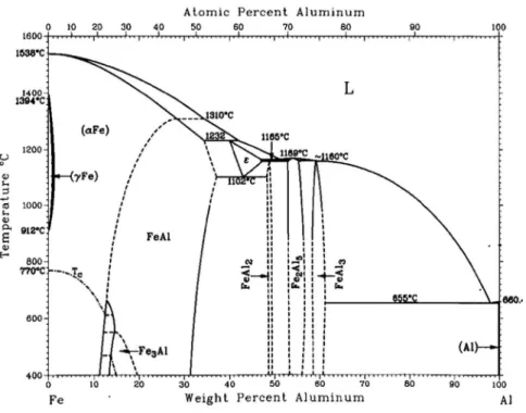
These intermetallic medial layers have been usually identiied by their very high hardness which several times over hardness of each one of the metals, including iron and aluminum. For example, researches of Tricarico6 have shown
that intermetallic compounds, including FeAl3 and Fe2Al5 with
approximate hardness of 740-900 HV have been established in the bonding area as well, and thickness of these layers depended on welding conditions has been reported up to 100 μm approximately. On the basis of viewpoints of Sauthof5,
one of the basic parameters inluencing on the formation of the intermetallic compounds is rate of the plastic bowing down of the welded elements as a result of shock wave developed during explosive welding process. Ian Leszeczynski7 believe
that these created layers are U-Technique phase of Al+FeAl3,
and rate of FeAl3 is increased by heat increase in the interface. Also, they have referred to this point that Fe2Al5 phase
may have been developed in the interface of bonding. Also, researches have shown that hardness in the smooth interface
in two-part bonding of Al/steel is less than wavy shape that this subject is due to the lessness of rate of bowing energy inculcated in smooth interface compared to bowing energy inculcated in wavy interface. As a result, very little energy has been available in order to form uncommon phases and phenomenon permeation and establishment of intermetallic compounds between two interfaces of bonding of Al/steel. In study of interface of bonding of steel to aluminum, six kinds of intermetallic compound being of Fe-Al type are observed shown in Table 1 so that, in areas next to the
steel, the compound is saturated by iron and, in areas to
aluminum, the compound is saturated by aluminum. In fact, compounds with high hardness (Higher than 800 HV) and with intermetallic compounds full of aluminum are factor of brittle interface6,7.
2. Materials and Research Method
The alloys used in the explosive welding process are taken into account for the purpose of establishment of two-part tube, 321 austenitic stainless steel and 1230 aluminum alloy which their chemical compound has been shown in Table 2. 321 austenitic stainless steel with length of 200 mm, thickness of 4.5 mm, internal diameter of 126 mm and external diameter of 135 mm has been selected as the base tube and 1230 aluminum alloy tube as the lyer tube in the explosive welding which dimensions of the samples have presented in Table 3. The metal aluminum had low strength and thickness; therefore, it was placed inwardly as the lyer
Table 1: Intermetallic compounds Fe-Al 7
Density (gcm-3) Micro hardness(HV) Structure Quantity Al (at-%) Phase
6.67 250 - 350 bcc 25 Fe3Al
5.37 400-520 bcc 50 FeAl
... 650-680 bcc 63 Fe2Al7
4.36 1000-1050 Rhombohedral 66/67 FeAl2
4.11 1000-1100 Orthromobic 69.7-73.2 Fe2Al5
3.95 820-980 Monoclinic 74-76 FeAl3
Table 2: Chemical compound of the explosive welding tubes
Element
(wt-%) C Si Mn P S Mg Cr Ti Ni Cu V Zn Al Fe
AlSI321 0.08 0.75 2 0.04 0.03 ... 18 ... 10.5 ... ... ... ... Balance
AA1230 ... 0.7 0.05 ... ... 0.05 ... 0.03 ... 0.1 0.05 0.10 Balance 0.7
Table 3: Dimensions of 1230 aluminum tube
No of tube Length (mm) Thickness (mm) External dia. (mm) Internal dia. (mm)
1 240 1.5 121 124
2 240 1.5 120 123
3 240 1.5 119 122
4 240 1.5 118 121
tube so that bonding is to be performed easily by the plastic deformation resulted from explosion.
Quantity of hardness of the austenitic stainless steel and aluminum was 200 and 40 HV, respectively. In order to bond the samples, explosive material of Amatol with compound of trinitrotoluene (T.N.T) and aluminum nitrate was used. For the purpose of bonding of the samples No 1and No 2, compound of 79% aluminum nitrate and 21% T.N.T with explosion speed of 3650 m/s was used and, for samples No 3 and No 4, compound of 95% aluminum nitrate and 5% T.N.T with explosion speed of 2504 m/s was used.
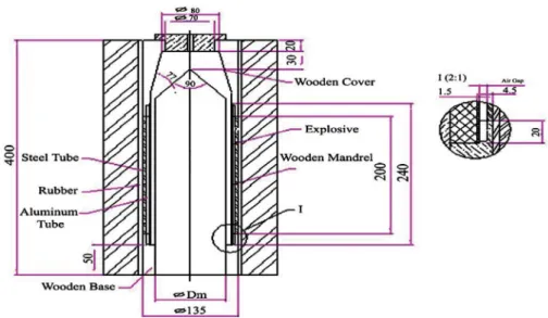
This research has carried out experimentally in which stand- of distance was selected as variable. Four stand- of distance of 1, 1.5, 2 and 2.5 mm were considered for bonding of the samples of No 1 to No 4, respectively. In (Figure 2), regulatory system of this research which is in form of load/ explosion from internal and explosion to external welding has been shown. Characteristics of the welding tests have been shown in Table 4.
For the purpose of structural studies, the samples were sand papered by emery No 60 to 2500 irstly and, after polishing with aid of the diamond-like dough and/or Al2O3 solution,
they were studied and observed under various magniications in the interface area and intermetallic compounds established in it by optical microscope, scanning electron microscope and EDS analysis (Energy Dispersive x-ray spectrometry). In order to prepare one sample according to (Figure 3), sample were isolated by hand stone or mill/cuter, and the isolated samples become mount (were mount) by the apparatus. After polishing, their surface was washed by alcohol and
dried, and then they became etched chemically by solution
of (Glycerin + Nitric acid, Chloride acid). Thickness of layer of intermetallic compounds, were measured as well. Shape of interface and intermetallic compounds were analyzed by optical microscope, Metallux 3 model.
In order to study mechanical properties of the samples, mechanical tests, including test of tensile, shear and microhardness strength were carried out on the welding samples. In order to evaluate tensile shear properties, some samples were provided on the basis of standard of the ASTM D 3165-958. This test was carried out by the Instron apparatus.
According to this standard, the samples must be designed in such a manner that both lyer metal and base metal have a groove with an appropriate distance from each other. Length of the test area (L) can be considered as a variable, but the length suggested in the standard is 12.7 + 0.3 mm. Also, distance of edge of the apparatus’s jaw up to edge of the groove in each metal is in a range from 50.8 mm to 63.5 and distance of direction of placement of the apparatus’s jaw on the sample is equal to 25.4 mm. Rate of the tensile force in this standard has been determined to be 1.27 mm/min. Dimensions and apparent shape of the samples, according to the standard, have been shown in (Figure 4).
Vickers microhardness test, by Buhler model apparatus, with an implemented force of 50 gr was carried out on the basis of ASTM E 384-119 from various areas of thickness of
Shiran et al.
294 Materials Research
Figure 2: Regulatory system of explosive welding
Table 4: Characteristics of the explosive welding tests
Test No Stand-of
distance
Thickness of the explosive material (mm)
Explosive material
Explosion speed
(m/s) Flyer pipe (mm)External dia. of base pipe (mm)Internal dia.of
1 1 10.7 Amatol 3650 124 126
2 1.5 10.8 Amatol 3650 123 126
3 2 7 Amatol 2504 122 126
4 2.5 6.95 Amatol 2504 121 126
Figure 3: Dimensions of the metallographic samples
Figure 4: Shape and dimension of the sample in order to carry
out tensile-shear test according to the standard ASTM D 3165-958
3. Results and Discussion
3.1 A Study of Micro Structure Optical
Microscope
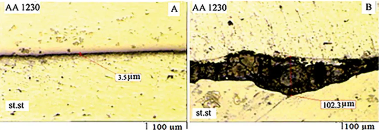
Figure 5: Interface of the samples' bonding with diferent stand- of distance. (a) AS1 sample with stand- of distance of 1 mm. (b) AS4 sample with stand- of distance of 2.5 mm.
surface; by increase of the consumed kinetic energy, higher plastic deformation is established in the interface and, through this increase, behavior of the material has inclined toward more luidity led to establishment of the waves with more wave and amplitude in the interface. Increase of stand- of distance and dynamic angle of the collision has led to increase of deformation of the lyer plate while colliding and a more intense deformation has established in the interface. Increase of collision speed has been led to raising of pressure from proof stress of two metals in the collision point. Speed of the lyer plate’s movement has been increased by increase of stand- of distance and explosive force and, also, due to existence of diference in density and speed of wave’s movement in the metals, pressure momentum in two directions of the interface has changed by increase of speed of the lyer plate’s movement, and, as a result, collision point, while bonding, has been involved in oscillation. By increase of the collision
speed, these oscillations have increased, and materials, in
proximity to the collision point, have lost their strength in higher volume and shown quasi-luid plastic behavior10,11.
As a result, wave length in the interface of bonding has been increased gradually by increase of the collision speed.
3.2 A study of microstructure by scanning
electron microscope
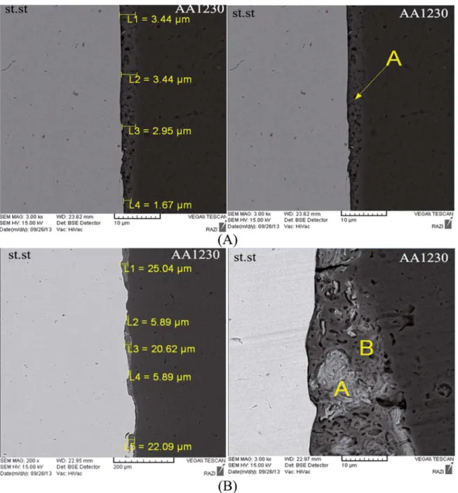
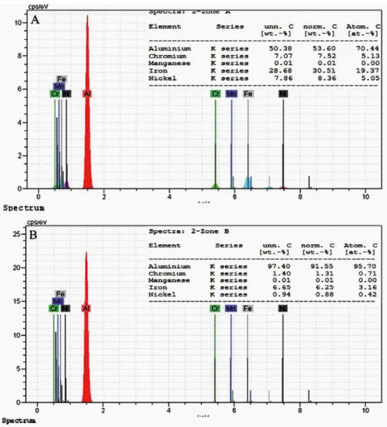
(Figure 6(a)) has shown pictures of scanning electron microscope regarding AS1 sample interface and thickness of the layers in some points. In the obtained results, it has been observed that compound of the area includes 96% of atomic aluminum and 2.2% of atomic percent. (Figure 6(b)) has shown microstructure of interface and intermetallic layer of AS2 sample with stand- of distance of 1.5 mm. Thickness of layer of intermetallic compounds is 6-25 μm appoximately which has been increased compared to thickness of layers of AS1 sample.
Two kinds of A and B intermetallic compound in this layer was speciied by analysis. In (Figure 7), analysis of
their elements has been presented. In B point, the compound includes 92.2 (percentage of) aluminum and 4.6 (percentage of) iron.
Reason for this much diference is closeness of this compound to aluminum metal, but, in point A next to austenitic stainless steel, their atomic proportion is 3:1. Interface of bonding of aluminum to steel is asymmetrical due to the density diference of two wavy-eddy alloys. Also, due to highness of the stand- of distance among aluminum plates and higher collision speed of the lyer plate, higher collision kinetic energy has been transferred to interface and led to establishment of wavy-eddy-shaped interface. In the explosive welding, two metal to metal and metal to frozen molten interfaces can be achieved in the interface. As a result of collision of the lyer plate, consumed kinetic energy has been converted into potential energy and led to deformation of the collision surfaces. If amount of the plastic deformation is not enough, short waves are established and positional melting area is not appeared. By increase of collision kinetic energy, intense deformation is occurred beneath the wave and it’s corona, and, as a result of the high collision pressures, vortexes/eddies are formed in the interface of bonding and these vortexes may create topical/ positional melting areas in some areas of interface. According to Zolbin12, internal
heat formed on the basis of high pressure resulted from shocking waves of explosion, intense plastic deformation and creation of lack-of-exit heat as a result of the vortex caught in front of some waves has been established due to deformation from kinetic energy into heating energy during confrontation and/or adiabatic heat arisen from the gases imprisoned among the plates.
These positional regions have been surrounded by the around cold metal, and they are under a high cooling speed
about 105-107 ok/s. These small regions have been observed
Shiran et al.
296 Materials Research
Figure 6: Pictures of the SEM from the changes of thickness and intermetallic compounds speciied in the interface. (a) AS1 sample with
stand- of distance of 1 mm. (b) AS2 sample with stand- of distance of 1.5 mm.
suggest formation of a combined compound from two alloys
in these positional areas based on turbulent and rotator
movement of the caught (trapped) jet established from both two base and lyer plates in these areas. Formation of the leaping jet from both two base and lyer plates and it’s rotator/movement have been observed by other researchers as well13,14.
For non-homogenous compounds, on the basis of relection of jet from the plate with less density, pressure is implemented on the plate with higher density and, thus, the vortex/eddy formed in the behind of waves contains more
Figure 7: EDS Analysis from speciied intermetallic compounds. (a) AS1 sample – (b) AS2 sample of region A – (c) AS2 sample of B
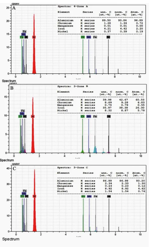
In AS3 sample as shown in (Figure 8), thickness of the intermetallic layer has luctuated in a range from 6 to 66.2 μm and shape of interface has been wavy. In this sample, two intermetallic areas of A and B have been speciied which proportion of iron to aluminum in point A is 1:3.5, and considering that this layer has been consisted of 70.4%
(percentage) of atomic aluminum and 19.3% (percentage) of atomic iron, the analysis shown in (Figure 9(a)), with regard to iron-aluminum diagram, shows that the compound layer locates in Fe2Al5 area.
Shiran et al.
298 Materials Research
Figure 8: Pictures of SEM from changes in thickness and speciied intermetallic compounds of the interface. (a) AS3 sample with
stand-of distance stand-of 2 mm –(b) AS4sample with stand-stand-of distance stand-of 2.5 mm
the researchers’ results. Heating stress ields and bowing of residue resulted from diference of heating conductance of two metals have increased thickness of layer of the intermetallic compounds which have a frangible and brittle nature. As shown in Figure 8(b) and (Figure 9(b)), by increase of the stand- of distance up to 2.5mm in AS4 sample, interface and it’s compounds are wavy shaped completely and with higher width compared to AS3 samples through conditions of equal
Figure 9: EDS analysis from speciied intermetallic compounds. (a) AS3 sample of A area – (b) AS3 sample of B areas
collision angle and collision speed, along with shear stress, has been mentioned as deformations of the interface15,16.
Thickness of layer of the intermetallic compounds in this sample has been measured from 2.6 to 85.4 μm. In (Figure 10(a) and (b)), two areas speciied by scanning electron microscope have been shown. Layer A consists of 74.5% (Percentage) of atomic aluminum, 17.4% of atomic iron, and layer B includes 92% (percentage) of atomic aluminum and 5.4% of atomic iron.
3.3 Microhardness assessment test
In the explosive welding, lyer plate and base plate are exposed to intense stressful wave resulted from explosion of the explosive material. These intense stressful waves cause metallurgical changes leading to increase of microhardness. Microhardness is a function of the chemical; compounds,
percentage of alloying elements, intermetallic compounds, heating changes, explosion force and stand- of distance16.
Table 5 has shown results of the microhardness test. Microhardness in the intermetallic area of AS1 HV and in the intermetallic area of AS2 with stand- of distance of 1.5 mm has been 766 HV. Reason for increase of microhardness of AS2 sample compared to AS1 sample is that increase of stand- of distance has increased speed of lyer plate and dynamic angle of collision and, therefore, collision kinetic energy has increased as well, and an intense plastic deformation has occurred in interface bonding and increased shocking hardness resulted from waves of microhardness explosion17.
Shiran et al.
300 Materials Research
Figure 10: EDS analysis from speciied intermetallic compounds. (a) AS4 sample of A area – (b) AS4 sample of B area
Table 5: Microhardness of layer of intermetallic compounds in diferent stand-of distance
Sample Thickness of explosive materials (mm) Stand-of distance (mm) Explosion speed (ms-1) Microhardness (HV)
AS1 10.7 1 3650 650
AS2 10.8 1.5 3650 766
AS3 7 2 2504 780
AS4 6.95 2.5 2504 927
3.4 Tensile – shear test
Results of the tensile – shear test presented in table 6 showed that rate of tensile – shear strength in the AS1 and AS2 samples has obtained to be 103.2 and 156 MPa, respectively. As the results show, amplitude of waves, due to plastic deformation, has been higher and a mechanical lock has established in it which is efective on increase of strength by increase of stand- of distance in AS2 to 1.5
mm18. In AS3 and AS4 samples, it has been observed that,
due to increase of wave length leads to improvement of mechanical properties shown in Table 6 of this problem.
Table 6: Tensile-shear strength of layer of intermetallic compounds with various stand-of distance
Sample Thickness of explosive materials (mm) Stand-of distance (mm) Explosion speed (ms-1)
Strength (MPa)
AS1 10.7 1 3650 103.2
AS2 10.8 1.5 3650 156.57
AS3 7 2 2504 181.11
AS4 6.95 2.5 2504 214.5
4. Conclusion
In this research, efect of stand- of distance on the mechanical and metallurgical properties of the explosive bonding of 321 austenitic stainless steel tubes to 1230 aluminum was studied, and, by study of the tests, following results were achieved:
1. By increase of the stand- of distance from 1mm to 2.5 mm, thickness of layer of the intermetallic compounds has been increased from 3.5 to 102.3 due to higher plastic deformation originated from high collision kinetic energy.
2. By increase of stand- of distance due to plastic deformation and higher wavy shape of interface, decrease of atomic percentage of aluminum and increase of atomic percentage of iron, nickel and chromium, microhardness of the intermetallic compounds has been increased from 650 HV in a sample with stand- of distance of 1 mm to 927 HV in a sample with stand- of distance of 2.5 mm. 3. Due to brittle nature of the intermetallic compounds,
ine cracks have been established along a direction being perpendicular to interface of bonding. 4. By increase of explosive force, shape of seam/issure
of bonding has become wavy higher and increased thickness of layer of the intermetallic compounds with brittle and fragile nature.
5. Increase of stand- of distance from 1 mm to 2.5 mm has led to the more plastic deformation and higher wavy shape of the bonding’s interface and increased strength from 103.2 MPa to 214.5 MPa. 6. In this research, AS4 sample with stand- of distance
of 2.5 mm and welding speed of 2504 m/s has been the best sample with respect to bonding. Due to increase of wave length, established mechanical lock has been led to improvement of the mechanical properties.
5. References
1. Sun XJ, Tao J, Guo XZ. Bonding properties of interface in Fe/ Al clad tube prepared by explosive welding. Transactions of Nonferrous Metals Society of China. 2011;21(10):2175-2180. 2. Kengkla N, Tareelap N. Role of Intermetallic Compound on
Corrosion of Aluminium/Steel Transition Joint Used in Naval Applications. In: Proceedings of the 2nd Mae Fah Luang University International Conference 2012 (MFUIC2012) on the Future Challenges Towards ASEAN Integration; 2009 29 Nov-1 Dec; Chiangrai, Thailand.
3. Kosec B, Kosec L, Čevnik G, Fajfar P, Gojić M, Anžel I. Analysis of interface at explosive welded plates from low-carbon steel and titanium. Mettalurgy. 2004;43(2):83-86.
4. Blazynski TZ, ed. Explosive Welding, Forming and Compaction.
Dordrecht: Springer; 1983.
5. Sauthof G. Intermetallics. 2nd ed. Weinheim: Wiley-VCH; 2008.
6. Tricarico L, Spina R, Sorgente D, Brandizzi M. Efects of heat treatments on mechanical properties of Fe/Al explosion-welded structural transition joints. Materials & Design. 2009;30(7):2693-2700.
7. Leszeczynski T. Structure and Properties of St41+A1 Aluminum Joints Produced by Explosive Welding. Welding International. 1992;6(5):347-350.
8. American Society for Testing and Materials (ASTM). D 3165-95. Standard Test Method for Tension Shear. West Conshohocken: ASTM; 2012.
9. American Society for Testing and Materials (ASTM). E384-11. Standard Test Method for Knoop and Vickers Hardness of Materials. West Conshohocken: ASTM; 2012.
10. Akbari-Mousavi SAA, Barrett LM, Al-Hassani STS. Explosive welding of metal plates. Journal of Materials Processing Technology. 2008;202(1-3):224-239.
11. Kahraman N, Gülenç B. Microstructural and mechanical properties of Cu-Ti plates bonded through explosive welding process.
Journal of Materials Processing Technology. 2005;169(1):67-71. 12. Zlobin BS. Explosion Welding of Steel with Aluminum.
Combustion, Explosion and ShockWaves. 2002;38(3):374-377. 13. Ettaqi S, Langlois L, Bigot R. Cobalt-based superalloy layers
deposited on X38CrMoV5 steel base metal by explosion cladding process. Surface and Coatings Technology. 2008;202(14):3306-3315.
14. Akbari Mousavi SAA, Al-Hassani STS, Atkins AG. Bond strength of explosively welded specimens. Materials & Design. 2008;29(7):1334-1352.
15. Akbari Mousavi SAA, Farhadi Sartangi P. Efect of post-weld heat treatment on the interface microstructure of explosively welded titanium-stainless steel composite. Materials Science and Engineering: A. 2008;494(1-2):329-336.
16. Lokaj J, Turna M, Jakubcek E, Benak M. X ray Microanalysis of Al-Austenitic Steel Boundary Formed by Explosion Welding.
Shiran et al.
302 Materials Research
17. Benák M, Turňa M, Ožvold M, Nesvadba P, Lokaj J, Čaplovič L, et al. Study of Al-austenitic steel boundary formed by explosion welding. In: METAL 2010: 19. Mezinárodní Konference Metalurgie a Materiálů; 2010 May 18-20; Rožnov pod Radhoštěm, Czech Republic. TANGER; 2010. p. 235-240.