Universidade do Minho
Escola de Engenharia
André Lopes Barbosa
Universidade do Minho
Dissertação de Mestrado
Escola de Engenharia
Departamento de Informática
André Lopes Barbosa
Pattern based user interface generation
Mestrado em Engenharia Informática
Trabalho realizado sob orientação de
Abstract
Human Computer Interaction (HCI) is one of the most important aspects in software development. In order to produce valuable products, software companies are focusing more on the users and less on the technology behind their products. This calls for new prospects for development cycles. Traditional methodologies are focused on the internals and there is little support to build a User Interface (UI) in a more iterative manner [12].
Model Driven Development (MDD) [21] is a technique that has been used to increase software quality and boost development time. With MDD organizations are able to implement iterative development methodologies that start with high level models that are iteratively transformed into lower level models and ultimately source code in an automated way. High level models have several advantages be-cause they are platform independent, easier to maintain, easier to reuse and ulti-mately they serve as documentation for the project.
Unified Modelling Language (UML) is an industry standard language for mod-elling software. The problem with UML is that it’s not fit for UI models [4]. The UI requires a new modelling language that is able to represent UI aspects accurately. The HCI community came up with several solutions for this problems, ITS [28], WISDOM [16], Unified Modeling Language for Interactive Applications (UMLi) [4] and USer Interface eXtensible Mark-up Language (UsiXML) [23] are some examples on this matter.
This work proposes a method to reuse previous UI knowledge using patterns of high level models. The goal of this work is to improve the way developers build UI’s and maximize re-usability. Patterns are tested and robust solutions that have been used in other contexts and can even persist between different projects and teams. This work integrates in the Forward Engineering method (FEM) developed by the UsiXML community and uses the UsiXML User Interface Description Language (UIDL) to represent patterns of high level UI models.
We developed a pattern definition using a set of descriptive fields and UsiXML models. With the information provided by the pattern we are able to perform model transformations from the domain and task models to an Abstract User In-terface (AUI) model. This gives developers the ability to reuse the structure of a UI developed in other context with a similar objective. This makes it easier for devel-opers with little knowledge in HCI to develop good UI’s and also helps development teams to maintain consistency across an application.
Resumo
A Human Computer Interaction (HCI) assumiu-se como um dos aspectos mais importantes no desenvolvimento de software. Por forma a criar produtos com maior qualidade, as empresas de software est˜ao a desviar o foco da tecnologia para os utilizadores, exigindo novas abordagens para os ciclos de desenvolvimento. As me-todologias tradicionais s˜ao mais focadas em aspectos internos e h´a pouco suporte para construir a User Interface (UI) de forma iterativa [12].
Model Driven Development (MDD) [21] ´e uma t´ecnica usada para aumentar a qualidade do software e diminuir o tempo de desenvolvimento. Com a MDD as organiza¸c˜oes s˜ao capazes de implementar metodologias de desenvolvimento iterativo que come¸cam com modelos de alto n´ıvel que s˜ao transformados, iterativamente, em modelos de n´ıvel inferior e, at´e chegar ao c´odigo-fonte. Modelos de alto n´ıvel tˆem v´arias vantagens porque s˜ao independentes de plataforma, mais f´aceis de manter, mais f´aceis de reutilizar e, finalmente, servem como documenta¸c˜ao do projeto.
Unified Modelling Language (UML) ´e uma linguagem padr˜ao da ind´ustria para modela¸c˜ao de software. O problema do UML ´e que n˜ao est´a apto para modelos de UI [4]. A UI requer uma linguagem de modela¸c˜ao nova, que seja capaz de representar os aspectos pr´oprios da UI com precis˜ao. A comunidade `a volta da HCI desenvolveu v´arias solu¸c˜oes para este problema, ITS [28], WISDOM [16], Unified Modeling Language for Interactive Applications (UMLi) [4] e USer Interface eXtensible Mark-up Language (UsiXML) [23] s˜ao alguns exemplos de projetos dentro desta ´area.
Este trabalho prop˜oe um m´etodo para reutilizar conhecimento passado sobre a UI usando padr˜oes de modelos de alto n´ıvel. O objetivo deste trabalho consiste em abordar melhorias `a forma como se constroem UI ’s e maximizar a sua reutiliza¸c˜ao. Padr˜oes s˜ao solu¸c˜oes testadas e robustas, que foram utilizadas em outros contextos e podem at´e persistir entre diferentes projetos e equipas. Este trabalho integra-se no m´etodo Forward Engineering (FEM) desenvolvido pela comunidade do UsiXML e usa a User Interface Description Language (UIDL) do UsiXML para representar padr˜oes de modelos de UI de alto n´ıvel.
Neste trabalho desenvolveu-se uma defini¸c˜ao de padr˜ao usando um conjunto de campos descritivos e modelos em UsiXML. Com a informa¸c˜ao fornecidas pelos pa-dr˜oes ´e poss´ıvel realizar transforma¸c˜oes de modelos a partir dos modelos de dom´ınio e tarefa e gerar um modelo de Abstract User Interface (AUI). Isto oferece aos enge-nheiros de software a capacidade de reutilizar a estrutura de uma UI desenvolvida noutro contexto com um objetivo similar. Assim torna-se mais f´acil para engenhei-ros com pouco conhecimento em HCI desenvolver boas UI ’s e tamb´em ajuda as equipes de desenvolvimento a manter consistˆencia ao longo de uma aplica¸c˜ao.
Acknowledgements
First of all I want to thank my supervisor, Professor Ant´onio Nestor for his guidance, pa-tience, trust and support, even when that meant working nights. I also want to say thank you to Professor Jos´e Creissac for providing me with all the documentation developed by the UsiXML community.
Thank you to all my friends for your support, understanding and good humour. Above all, thank you for helping me keep my sanity. Special thanks to Samuel for his companionship during this long summer spent at the university. Next dinner is on me.
Thank you to my family for always making me feel special. Thank you to my grandfather for teaching me the value of hard work. Thank you to my mother for her support and delicious food. Thank you to my father for never letting me give up. Thank you to my brothers for making me feel so proud. Thank you to my goddaughter for being so cute.
Contents
1 Introduction 1 1.1 Motivation . . . 2 1.2 Objective . . . 3 1.3 Dissertation Outline . . . 3 2 Background 7 2.1 Early days . . . 9 2.1.1 ITS . . . . 102.2 Optimization-based generation of interfaces . . . 11
2.2.1 Gadget . . . 11
2.2.2 Supple . . . 13
2.3 User interface patterns . . . 15
2.3.1 IdealXML . . . 16 2.4 Specification languages . . . 18 2.4.1 UMLi . . . 19 2.4.2 WISDOM . . . 22 2.4.3 UsiXML . . . 23 2.5 Discussion . . . 26 3 UsiXML 29 3.1 UsiXML semantics . . . 30 3.2 UsiXML method . . . 31 3.2.1 Spem4UsiXML . . . 32
3.2.2 Forward engineering method . . . 36
4 Patterns in UsiXML 39 4.1 Concept . . . 40
4.3 Example . . . 43
4.4 Requirements . . . 46
4.5 Algorithm . . . 48
5 UsiXML patterns tool 51 5.1 Package org.usixml . . . 52 5.2 Package org.usixml.aui . . . 53 5.3 Package org.usixml.domain . . . 54 5.4 Package org.usixml.task . . . 56 5.5 Package usixmlpatterns . . . 58 5.6 Implementation details . . . 59 6 Case study 63 6.1 Patterns . . . 63
6.1.1 List Documents Pattern . . . 64
6.1.2 Create document pattern . . . 66
6.1.3 Edit document pattern . . . 69
6.2 Case study models . . . 71
6.2.1 List Prescriptions . . . 72
6.2.2 Create Prescription . . . 74
6.2.3 Edit Prescription . . . 78
6.3 Case Study Implementation . . . 81
7 Conclusions and Future Work 85
List of Figures
2.1 Login window modelled in UMLi . . . 19
3.1 UsiXML specification as an UML class diagram. . . 30
3.2 Structure of the Spem4UsiXML meta-model. . . 33
3.3 Structure of the Spem4UsiXML method content meta-model package. . . 33
3.4 Structure of the Spem4UsiXML process structure meta-model package. . 35
3.5 The forward engineering method. . . 37
4.1 The first stage of the forward engineering method. . . 40
4.2 Proposal for the first stage of the forward engineering method. . . 41
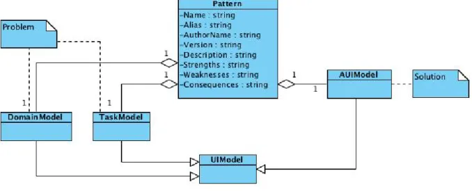
4.3 UML specification of user interface conceptual pattern. . . 42
4.4 UML specification of the Create document pattern’s domain model. . . . 43
4.5 Task model for the Create document pattern. . . 44
4.6 Abstract User Interface model for the Create document pattern. . . 45
4.7 UML specification of an invoice’s domain model. . . 45
4.8 Task model to create an invoice. . . 46
4.9 Abstract User Interface model to create an invoice. . . 47
5.1 The org.usixml package. . . 52
5.2 The org.usixml.aui package. . . 53
5.3 The org.usixml.domain package. . . 55
5.4 The org.usixml.task package. . . 57
5.5 The usixmlpatterns package. . . 58
5.6 The UsiXMLPatterns User Interface (UI). . . 61
5.7 The UsiXMLPatterns UI to choose a path in the local file system. . . 61
5.8 Junit tests on Netbeans. . . 62
6.1 UML specification of a document domain model. . . 64
6.3 List documents pattern’s task model. . . 66
6.4 Create document pattern’s task model. . . 67
6.5 Create document pattern’s task model. . . 68
6.6 Edit document pattern’s task model. . . 70
6.7 Edit document pattern’s task model. . . 71
6.8 UML specification of a medical prescription domain model. . . 71
6.9 List prescriptions task model. . . 72
6.10 Using UsiXMLPatterns to genera the AUI model to list prescriptions. . . 73
6.11 AUI model to list prescriptions. . . 74
6.12 Task model to create a medical prescription - part 1. . . 75
6.13 Task model to create a medical prescription - part 2. . . 76
6.14 Task model to create a medical prescription - part 3. . . 76
6.15 AUI model to create a prescription. . . 77
6.16 Task model to edit a prescription - part 1. . . 79
6.17 Task model to edit a prescription - part 2. . . 79
6.18 Task model to edit a prescription - part 3. . . 80
6.19 Task model to edit a prescription - part 4. . . 80
6.20 AUI model to edit a prescription. . . 81
6.21 Prescriptions List. . . 82
6.22 New Prescription. . . 83
A.1 Structure of the SPEM 2.0 meta-model. . . 94
A.2 Structure of the SPEM 2.0 method content meta-model package. . . 95 A.3 Main classes and associations of SPEM 2.0 process structure package package. 97
Acronyms
AUI Abstract User Interface BHW Better Hand Writing CTT Concur Task Trees DRY Don’t Repeat Yourself
FEM Forward Engineering method GUI Graphical User Interface HCI Human Computer Interaction
IDE Integrated Development Environment
MB-UIDE Model Based - User Interface Development Environment MDD Model Driven Development
MDDUI Model Driven Development of User Interfaces MDE Model Driven Engineering
OMG Object Management Group SDK Software Development Kit
SPEM Software & Systems Process Engineering Metamodel SPEM4UsiXML SPEM for UsiXML
UI User Interface
UIDL User Interface Description Language UML Unified Modelling Language
UsiXML USer Interface eXtensible Mark-up Language
WISDOM Whitewater Interactive System Development with Object Models XML eXtensible Mark-up Language
Chapter 1
Introduction
Nowadays what makes a software product stand out is getting less technological and more related to how it handles the Human Computer Interaction (HCI). This may not be true to every software product but it’s true for most of them. Usability aspects can’t be neglected in any software and this has brought a lot of work in this field by both the industry and academic communities.
Recent years have seen the proliferation of many types of computers and devices. In order to perform their tasks, people now have available a wide variety of computational devices ranging from traditional computers and laptops to mobile phones, tablets and even televisions. While this increasing proliferation of fixed and mobile devices fits with the need for ubiquitous access to information processing, this diversity offers new challenges to the HCI software community like building and maintaining versions of single applications across multiple devices.[3]
Model Driven Development (MDD) defining characteristic is that software development’s primary focus and products are models rather than computer programs. The major advantage of this is that we express models using concepts that are much less bound to the underlying implementation technology and are much closer to the problem domain relative to most popular programming languages [21].
Models are easier to maintain than the code itself and, most importantly, they’re platform independent. This means that the same model can be used to generate code that runs on a desktop environment, a web environment or even a mobile environment. This makes a lot of sense for user interfaces because modern applications are becoming more and more ubiquitous and it’s highly complex and time consuming to build a Graphical User
Interface (GUI) for every supported platform.
MDD is a good solution for the ubiquity problem but alone can’t solve all HCI con-cerns that are as much important. Usability comes from experience and experimentation. Building intuitive applications isn’t an easy task. Usually it’s an iterative process where developers observe the needs of the users, build a version, put it to test with real users, improve it and repeat the process. Of course this isn’t always possible because it takes a lot a time and money.
By combining MDD of user interfaces and promoting the reuse of past developments these two problems can be tackled at once. Patterns are widely used in several fields of engineering (including software engineering) but are still a bit underutilized in the HCI community. Most patterns repositories only contain implementation level models and are designed to be read by humans instead of being processed by computers. This means there is a gap in the utilization of patterns. There’s a lack of more high level pattern definitions that could be used in the MDD process and help and serve as a base knowledge to help developers make decisions and automate models transformations.
1.1
Motivation
Most developers spend a lot of their times designing their applications in a way that they won’t have to repeat any code line (Don’t Repeat Yourself (DRY)) even between separated projects. When it comes to the User Interface (UI) things can sometimes get out of hand. This happens mainly because most developers don’t start building UI’s the same way they build the core of their applications, that is modelling first. The lack of UI models many times result in poor reuse of previous knowledge and sometimes even in poor UI’s. This happens mainly because there isn’t a standard language for modelling UI’s (like Unified Modelling Language (UML)).
USer Interface eXtensible Mark-up Language (UsiXML) is a new and powerful language that has the potential to change the status quo and become a standard for modelling the UI in a MDD compliant way with support for different phases and levels of abstraction. Having solved the problem of creating models, the next logical step is to create tools suited to help developers reuse models and previously acquired knowledge. In other words, tools to improve existing Model Driven Development of User Interfaces (MDDUI) methodologies using patterns.
1.2
Objective
The main objective of this work is to develop a tool that integrates in the MDDUI methodology developed by the UsiXML community (Forward engineering method 3.2.2) and uses patterns to automate the first stage of model transformations.
The first transformation of the Forward engineering method receive as input a Task and a Domain models and should output an Abstract User Interface (AUI) model.
The objective is to develop a tool that will help developers with this transformation. The creation of the AUI model is one of the most complex models in UI modelling[22]. That’s because developers have to specify what components will appear in every kind of window. The objective of this work is to use patterns to help in this stage. Instead of leaving the hard work for developers or to create a complex optimization algorithm, our approach is to leverage from previous knowledge and use it to effectively boost the development time and quality.
With this objective in mind this tool have to meet the following requirements: • read and interpret Task, Domain and AUI models;
• link the Task and Domain developing models to the Task and Domain models of a pattern;
• generate an AUI model based on the information provided by the developing models and the pattern models.
This work intends to contribute with an alternative path for the first phase of the Forward Engineering method (FEM) (section 3.2.2).
Originally the first phase of the method receives a Task and a Domain models as input and outputs an AUI model through manual transformations. This work will contribute with a tool to automate this process by taking advantage of previous knowledge in the form of patterns.
1.3
Dissertation Outline
This work is divided into 7 Chapters. In the first chapter, the current one, we present an introduction to all the work undertaken for this dissertation.
1. Chapter 2: presents some background on MDDUI. In this chapter we present several projects that contributed for the development of the state of the art on this subject. We present some early projects that were very important in an historic manner. Projects that propose alternative approaches that are very different from the traditional. And finally we studied more recent projects with similar characteris-tics that attempt to solve the problem of introducing models into the development of UI’s. At the end of this chapter there’s a critic discussion of all the projects mentioned above.
2. Chapter 3: presents a detailed view over UsiXML. We begin by presenting an overview about the UsiXML project and its objectives. Afterwards we present the semantics of the UsiXML’s User Interface Description Language (UIDL), version 1.8. Finally we present the engineering method developed by the UsiXML project. The method is based on a meta-model, SPEM for UsiXML (SPEM4UsiXML) which is itself based on the Software & Systems Process Engineering Metamodel (SPEM) meta-mode that is approached on appendix A. After the meta-model we present the method itself, the FEM.
3. Chapter 4: presents a solution to leverage from UsiXML patterns at a conceptual level. Starts with a concept of how this should integrate in the FEM method. After we specify the contents of a pattern in order to satisfy the concept vision. The next section gives an example of how a pattern should look like and how it should be used. Afterwards we specify a set of requirements that should be met in order to implement the concept. The chapter ends with a description of an algorithm to perform the model transformation specified by the concept.
4. Chapter 5: presents the implementation of a prototype application that satisfies the requirements of the concept. In this chapter we start by describing a software architecture to satisfy the requirements mentioned in the previous chapter. We end this chapter with some implementation details like the developed UI for the prototype.
5. Chapter 6: presents a case study that uses the prototype application. In this chapter we develop models for the UI of an application called Better Hand Writing (BHW) that is meant to manage digital medical prescriptions. We start by stating the requirements of the application and choose the best suited patterns to use in its development.
In the last chapter we present this work’s conclusion and where future projects on this work should focus.
Chapter 2
Background
In this chapter is described the state of the art regarding Model Driven Development of User Interfaces (MDDUI). We’ll present several techniques to develop User Interface (UI)’s using Model Driven Development (MDD) principles. There is significant ongoing research in this field since the late 1980s and this chapter makes a short summary of that research.
MDD [21] defining characteristic is that software development’s primary focus and prod-ucts are models rather than computer programs. The major advantage of this is that we express models using concepts that are much less bound to the underlying implemen-tation technology and are much closer to the problem domain relative to most popular programming languages.
Models are easier to maintain than the code itself and, most importantly, they’re platform independent. This means that the same model can be used to generate code that runs on a desktop environment, a web environment or even a mobile environment. This makes a very important feature for UI’s because modern applications are becoming more and more ubiquitous and it’s highly complex and time consuming to build a UI for every supported platform.
There are different kinds of models and several techniques to model UI’s. Some tools like Janus[2] only require a domain model to generate a user interface while others like Trident[26, 25] and Adept[9] also use a task model. All these approaches automate part of the development process. Other approaches like ITS[28] require more work from the developers because they don’t generate any model.
or Supple[7] use numeric optimization techniques to generate better UI’s.
Patterns are widely used in every field of engineering. One of the earlier definitions of patterns can be found in [1]. Almost twenty years later patterns were brought to software engineering by Gamma et al. [8].
Patterns bring many advantages, not only they make the development of a product less time consuming and thus less expensive but can also guarantee a higher level of qual-ity because patterns are solutions that have been tested and used in other projects. IdealXML[14, 13] is a tool that helps developers to take advantage of patterns while developing UI models.
Although there have been a lot of academic work surrounding MDDUI, this work is struggling to be adopted by the industry. There are some theories of what’s missing, Molina [12] says that better tool support is needed while Montero et al. [14] says that a common language for representing UI models should the next step.
Unified Modelling Language (UML) [20] is the industry standard for software modelling but, unfortunately, is not completely fit to model UI’s. Fortunately, the software engineer-ing community has developed some new modellengineer-ing languages in the past few years to over-come this problem. Unified Modeling Language for Interactive Applications (UMLi)[4] is an extension to UML that provides an alternative diagram notation for describing Abstract User Interface (AUI) models. Whitewater Interactive System Development with Object Models (WISDOM)[16] is an engineering method for interactive software develop-ment that includes a notation for UI models.Concur Task Trees (CTT) [18] aims at task modelling by dividing the task model in three essential parts:
• First a hierarchical logical decomposition of the tasks represented by a tree-like structure;
• Then an identification of the temporal relationships among tasks at the same level; • And finally an identification of the objects associated with each task and of the
actions which allow them to communicate with each other.
USer Interface eXtensible Mark-up Language (UsiXML) [23] is a User Interface Descrip-tion Language (UIDL) aimed at expressing user interfaces built with various modalities of interaction and independently of them. UsiXML is eXtensible Mark-up Language (XML) compliant to enable flexible exchange of information and powerful communication be-tween models and tools used in UI engineering [23]. One of the great advantages of
UsiXML is platform independence providing a multi-path development of user interfaces [11]. UsiXML characteristics and features give it the potential to become a standard for modelling UI’s like UML is for software architecture.
There is a lot of work regarding MDDUI and the idea that models can simplify the development process is becoming more consensual. Section 2.1 focus on projects from the beginnings of MDDUI, namely Its, section 2.1.1, which was one of the most important and innovative projects of its time.
Section 2.2 will describe optimization based techniques and the Gadget and Supple projects will be examined with more depth.
Section 2.3 refers to the usage of patterns in UI design . This section also includes an analysis of IdealXML, a knowledge based tool for designing UI’s.
Section 2.4 is about specification languages for UI’s. We will look into UMLi, WISDOM and UsiXML with some detail.
2.1
Early days
Research in model-based user interface development comes from the 1980s[22]. Their roots come from user interface management systems (UIMS)[15]. These tools seeked to provide an alternative paradigm for constructing interfaces. Rather than using a toolkit library, developers would write a specification in a specialized, high-level specification lan-guage. This specification would be automatically translated into an executable program, or interpreted at run-time to generate the appropriate interface.
Through the 1980s and 1990s specification languages became more sophisticated, sup-porting richer and more detailed representations that allowed systems to generate more sophisticated interfaces.
Since that time there were essentially two approaches to model driven development of user interfaces. Some tried to minimize the work of developers and generate most of the model from just a domain model like in Janus[2] or a task model as in Trident[26, 25]. The second approach was to give more power to the developer letting him produce all or most of the work like in Its[28].
2.1.1
ITS
The Its[28] system was developed in the early 90s by the IBM research and develop-ment departdevelop-ment. It was successfully used to develop several large applications like the information kiosks for Seville Expo 92.
The Its architecture divides applications in four layers. The action layer implements the application’s back-end computations. The dialogue layer defines the content of the user interface independent of its style, much like an abstract user interface model. Content specifies the objects included in each frame of the interface, the flow of control among frames, and what actions are associated with each object. The style rule layer defines how the dialogue is presented to the user in terms of appearance and interaction techniques. Finally the style program layer implements the primitive toolkit objects that are composed by the rule layer into complete interaction techniques.
Before Its came along there were mainly two types of layered architectures that provided the required flexibility in application development. User Interface Management Systems (UIMS) and toolkits. UIMS separate the business layer from the interface. Back-end computations are separated from the dialogue control and style. Style, however, was often treated in a single interface layer. Toolkits separated style from the application. Dialogue control remained in the back-end while the implementation of interaction techniques is hidden in a code library.
The four layers in Its present a series of advantages that separate this tool from its predecessors. Like in previous UIMS there is a separation from back-end computations and the interface itself. By separating the action layer from the dialogue allows actions to be reused in different applications.
Splitting the interface into separate layers for style-independent dialogue, rule base and toolkit also gives some benefits. First, the dialogue remains independent of style. A dialogue can be mapped into any different style simply by firing the appropriate rule. Second, interface designers control style rather than application programmers. The rule layer represents the selection criteria for all interaction techniques.
Each layer in Its architecture corresponds to one of four roles in application development:
application programmer, application expert, style expert and style programmer. An
application expert is familiar with the domain of the application. The application expert typically is neither trained in software development or part of an information systems department. In Its, the application expert is the author of the dialogue. A style expert
may be a graphic artist or a human factors engineer. Rules give them direct control over style in Its.
Its is a specification-based system. The main difference between these tools from design tools like Janus[2] is that the modelling language is open whereas in automated-design tools are closed. By lifting this limitation for the developers the final result can have a higher level of quality although it’s dependent from the capabilities of the developer himself.
Even though Its is a specification-based system, this doesn’t mean that developers have to specify every feature of every individual window. Developers are forced to specify the content of dialogues which is equivalent to the abstract user interface and this is, as been proved to be by experience, the most difficult model to generate by the automated-design tools. The style rules layer or the concrete user interface model doesn’t have to be totally specified. This doesn’t mean that ITS generates this model but that developers can reuse rule sets from libraries that contain the abstract to concrete mapping for significant portions of the interface specifications.
2.2
Optimization-based generation of interfaces
Recent work is beginning to reveal that numerical optimization can play a role on mod-ern approaches for generating interfaces and displays. Gadget[6] and Supple[7] are two examples of this tendency.
The first is a framework that aims to provide developers with none or few knowledge on numerical optimization a set of tools that allows them to generate user interfaces through optimization methods.
The second is a tool that aims the generation of personalized user interfaces at run time. The main motivation behind Supple is that current user interfaces are developed with only a limited set of user abilities in mind leaving people with special needs with difficulties to interact with their applications.
2.2.1
Gadget
Although optimization-based techniques appear to offer several potential advantages most programmers are intimidated or uncomfortable by the math required to program an
opti-mization. Although optimization toolkits are available, they typically require substantial specialized knowledge because they have mostly been designed for physics simulations and other traditional optimization problems.
Gadget provides a set of abstractions for many optimization concepts along with a set of mechanisms to help programmers quickly create optimizations, including an efficient lazy evaluation framework, a powerful and configurable optimization structure, and a library of reusable components. A programmer creating an optimization using the Gadget tool-kit needs to supply three essential components: an initializer, iterations and evaluations. The initializer creates the initial solutions to be optimized. This might be based on an existing algorithm, or done randomly. Iterations are responsible to transform one potential solution into another, typically using models that are at least partially random. Finally, evaluations are used to judge the different notions of goodness in a solution. There’s a standard framework to abstract the concepts and constructs behind evaluations. Gadget allows programmers to focus on creating evaluations to measure criteria that are important to the problem. Gadget then combines these evaluations and uses them to choose between a set of possible solutions. This process is divided into five stages. First the framework presents each evaluation with the current potential solution, which is called the prior solution. Each evaluation returns an array of double values representing its interpretation of the prior solution. This collection of arrays of double values is called the prior result.
On the second stage the framework uses an iteration object to modify the prior solution and create a new one, called the post solution.
Third, the framework presents the post solution to each evaluation. Each individual evaluation returns interpretations that are then combined to create a post result.
In the fourth step, the framework uses a method to compare the prior result with the post result. This is possible by requiring each evaluation to be capable of comparing two arrays of double values that it has created and providing a double value in the range of −1 to 1, where −1 indicates the evaluation has a strong preference for the prior solution, 0 indicates that the evaluation is indifferent and 1 indicates that the evaluation has a strong preference for the post solution.
Finally, the result of this comparison indicates whether the framework should go with the post solution or revert to the prior solution. To choose between them, the values retrieved from the fourth step are multiplied by the weight associated with its respective
evaluation and then summed. If the sum is greater than 0, the framework prefers the post solution, else it reverts to the prior solution.
2.2.2
Supple
Most of today’s software interfaces are designed with the assumption that they are going to be used by an able-bodied person, who is using a typical set of input and output devices, who has typical perceptual and cognitive abilities, and who is sitting in a stable, warm environment. Any deviation from this pattern requires a new design. In [7] is argued that automatic personalized generation of interfaces is a feasible and scalable solution for this challenge. Supple can automatically generate interfaces adapted to a persons devices, tasks, preferences and abilities at run-time. It is not intended to replace user interface designers, instead it offers an alternative user interface for those people whose devices, tasks, preferences and abilities are not sufficiently addressed by the original designs. Support for users with special needs is often forgotten by interface designers. When this problem is addressed there are three popular patterns that are usually followed, manual redesign of the interface, limited customization support, or by supplying an external as-sistive technology. The first approach is clearly not scalable, new devices constantly enter the market, and people’s abilities or preferences both differ greatly and often cannot be anticipated in advance. Second, today’s customization approaches typically only support changes to the organization of tool bars and menus and cosmetic changes to other parts of the interface. Furthermore, even when given the opportunity, most people do not customize their applications. Finally, assistive technologies, while they often enable com-puter access for people who would otherwise not have it, also have limitations. They’re impractical for users with temporal impairments, they do not adapt to people whose abil-ities change over time and they’re often abandoned by people who need them because of factors like cost, complexity, configuration, and the need for ongoing maintenance. In contrast with this approach, Supple generates personalized interfaces to suit the par-ticular contexts of individual users. In order to be able to generate these personalized interfaces, Supple makes three important contributions:
• Defines an interface generation as a discrete constrained optimization problem and solve it with a branch-and-bound algorithm using constraint propagation. This general approach allows the Supple system to automatically generate “optimal” user interfaces given a declarative description of an interface, device characteristics,
available widgets, and a user and device specific cost function.
• Two types of cost functions were developed to guide the optimization process. The first is factored in a manner that enables preference-based personalization as well as fast computation, allowing Supple to generate user interfaces in under 1 sec-ond in most cases. The secsec-ond explicitly models a person’s ability to control the pointer, allowing Supple to generate user interfaces adapted to unusual interaction techniques or abilities, such as an input jittery eye tracker or a user’s limited range of motion due to a motor impairment.
• Supple also supports two approaches for dynamic personalization of generated in-terfaces: an automatic system driven adaptation to the current task, and a user driven customization.
Like other automatic user interface generation systems, Supple relies on an interface spec-ification (I). Additionally, Supple also uses an explicit device model (D) to describe the capabilities and limitations of the platform for which the interface is to be generated. Fi-nally, in order to reflect individual differences among usage patterns, Supple additionally includes a usage model, represented in terms of user traces (T ).
Supple adopts a functional representation of user interfaces that is, one that says what functionality the interface should expose to the user instead of how to present those fea-tures. Like a number of previous systems, Supple represents basic functionality in terms of types of data that need to be exchanged between the application and the user. Seman-tic groupings of basic elements are expressed through container types which also serve as reusable abstractions. Supple chooses not to adopt a task-oriented approach for two reasons. First, because task-oriented descriptions are typically first compiled into a data-oriented functional description. Second, task-data-oriented languages are particularly useful for capturing task-oriented processes such as store checkout or making a hotel reservation. Most direct manipulation systems, however, support a broad range of possible tasks and make simultaneously available numerous reversible actions. Such interfaces would not benefit significantly from a task-oriented representation.
Most people use only a small subset of functions available in any application, and different users use different subsets. To adapt to a person’s tasks and long-term usage patterns, the user interface should be rendered such that important functionalism is easy to ma-nipulate and to navigate to. Instead of relying on explicit annotations by the designer or the user, Supple relies on usage traces, which can correspond either to actual or antici-pated usage. Usage traces provide not just interaction frequency for primitive widgets,
but also frequencies of transitions among different interface elements. In the context of the optimization framework, traces offer the possibility of computing expected cost with respect to anticipated use.
Supple is an optimization-based tool to generate user interfaces. Unlike GADGET it is not a simple framework to be used by programmers, it implements all the optimization related logic. Developers are only obliged to supply the specification. Unlike most of the recent tools in this field, Supple only requires the abstract user interface model and a set of constraints, it doesn’t use tasks. The main advantage regarding other solutions is that constraint set is dynamic and depends both on the user and the device. This allows Supple to generate good user interfaces to every user even if the designer doesn’t have much information about the users preferences.
2.3
User interface patterns
Patterns are widely used in every field of engineering. One of the earlier definitions of patterns can be found on [1]. Almost twenty years later patterns were brought to software engineering by [8].
Patterns bring many advantages, not only they make the development of a product less time consuming and thus less expensive but can also guarantee a higher level of quality because patterns are solutions that have been tested and used in other projects.
Particularly on user interfaces, these are very important features because building a good user interface is a very complex and time consuming process. On most software projects it takes about half of the time frame allocated to that project, so patterns can help to make this process more efficient. Also there’s the problem of usability. This is one of the most important aspects of software projects but its still very difficult to build a user interface compliant with human computer interaction (HCI) rules. By using patterns this can be easily achieved if the patterns are already compliant with these rules.
Patterns are usually stored in catalogues. In [8] a pattern is composed by the following fields:
• The Pattern name resumes the pattern in one or two words that we use to refer to named pattern.
• The Solution describes how the pattern works, what elements it has and how they relate to each other.
• The Consequences describe the side effects of using the pattern.
This is the specification used for software design patterns but it’s also used in most user interface patterns catalogs. In [27] documentation of patterns is divided in two categories, descriptive patterns and generative patterns. Descriptive patterns are meant to be interpreted by humans so they describe the solution in a generic way so that the pattern can be used in a wide range of contexts while generative patterns maximize expressivity over genericity thus, they can be used in more restricted range of contexts but the solution is specific enough to be interpreted by machines.
Design patterns like the ones described in [8] are generative patterns because their solution is specified in UML which is a formal language that can be easily interpreted by machines to perform transformations.
A list of catalogues for user interfaces can be found in [5]. Most of these catalogues define their solutions with text and images because there isn’t a reference language to specify user interfaces. Thus most of these patterns are descriptive patterns that can only be used by humans.
In order to take full advantage of patterns we need a way to document them. Generative patterns are the most useful in the context of this project but to use them we need to find a language to specify these patterns so that they can be interpreted by a machine to generate a concrete user interface. applications. In section 2.3.1 is described IdealXML a tool for developing user interface models that takes advantages of patterns.
2.3.1
IdealXML
IdealXML[14, 13] is an experience-based environment for user interface design. Experi-ence is the accumulation of knowledge or skills that result from direct participation in events or activities. Developers have a strong tendency to towards reusing designs that worked well for them in the past. Unfortunately, this design reuse is usually limited by personal experience, and there is usually few sharing of knowledge among developers. IdealXML manipulates a pattern repository, where patterns are organized following a hierarchical structure. At the top, this structure has different models related with a Model Based - User Interface Development Environment (MB-UIDE): domain, task,
presentation and mapping, context and user models are left for future work. IdealXML is shipped with a predefined collection of patterns from a variety of sources. These patterns are the initial base of knowledge.
IdealXML is an MB-UIDE and designers can, using several graphical notations, specify domain models, task models, abstract presentation models and mapping models between them. Some of these models are stored in the pattern repository and new ones can always be added.
IdealXML also allows for the animation of a task model to generate a hi-fi prototype of the future user interface while still in the first development stages. This is achieved by using CTT [18], UsiXML [23] and a set of heuristics to transform the task model specification into an abstract UI.
Prototyping consists in the creation of a preliminary version of the future UI (prototype) so that the user and the experts can find possible problems in the design of the UI, both from the functional and from the usability points of view. Prototyping techniques fall into two main categories:
• Lo-fi: this family of techniques is mostly used in requirements analysis stage to validate the requirements with the user in user-centred approaches.
• Hi-fi: they are aimed at the creation of preliminarily versions of the UI with an acceptable degree of quality. This kind of techniques produces a UI prototype which is closer to final future one.
Abstract prototyping was devised because it was found that the sooner developers started drawing realistic pictures or positioning real widgets, the longer it took them to converge on a good design.
As it was mentioned above, IdealXML uses a set of heuristics to transform the task model into an abstract interface model:
• Each cluster of interrelated task cases becomes an interaction space in the navigation map, so an abstract task is a container.
• A container also can be an interaction task or an application task in a hierarchical task decomposition.
• A component rises when an interaction or application task is found in a hierarchical task decomposition.
• A component can have several facets (input, output, control and navigation). These facets allow the user to interact with the system.
The animation of the abstract user interface that resulted from the designed task model is grounded in the identification of the enabled task set (ETS). Having identified the ETC for a task model, the next step is to identify the effects of performing each task in each ETS. The result of this analysis is a state and transitions occur when tasks are performed. In IdealXML’s proposal, the task model specification is split into states. Each state is a set of interrelated tasks, including temporal relationships between those tasks, usually connected to an essential use case.
2.4
Specification languages
In [13] was stated that one of the most important challenges to overcome in model driven development of user interfaces is the creation of a specification language that would be massively adopted and became a common ground between developers like UML is for software architecture.
Over the years many languages were developed to try and overcome this obstacle. In [19] were enumerated some of the problems found with that time user interface models:
• Partial models, most models deal only with a portion of the spectrum of inter-face characteristics. Some emphasize domain, others emphasize tasks, some others emphasize presentation guidelines and so on.
• Insufficient underlying model, several model-based systems use modelling paradigms proven successful in other applications areas, but that come up short for interface development. These underlying models typically result in partial interface models of restricted expressiveness.
• System-dependent models, many interface models are non-declarative and are embedded implicitly into their associated model-based systems, sometimes at code level. These generic models are tied to the interface generation schema of their system, and are therefore unusable in any other environment.
• Inflexible models, experience with model-based systems suggests that interface developers often wish to change, modify, or expand the interface model associated with a particular model-based environment. However, model-based systems do not
offer facilities to such modifications, nor the interface models in question are defined in a way that modifications can be easily accomplished. Thus the inclusion of an open meta-model like in UML could be an important factor of success.
Next, two recent specification languages for user interfaces that try to overcome these problems will be presented. In section 2.4.1 will be presented UMLi, an extension to UML to support the modelling of user interfaces. Section 2.4.1, presents WISDOM [16], an engineering method for small software companies with an UML based notation with support for UI modelling. Finally, section 2.4.3 will be presented UsiXML, a language with potential to become a standard in user interface specification.
2.4.1
UMLi
Although user interfaces represent an essential part of software systems, UML seems to have been developed with little attention to specific details of user interface models. It’s possible to use UML to model important aspects of user interfaces but these models usually get widely unnatural.
UMLi[4] doesn’t try to replace UML entirely. The UMLi meta-model fully integrates with UML this makes possible to integrate UMLi models with other UML models. It is possible to model abstract and concrete interfaces using class models in UML. How-ever class models don’t provide an intuitive representation of the interface. UMLi provides an alternative diagram notation for describing abstract interaction objects.
Figure 2.1 shows an abstract user interface for a login windows modelled in UMLi. The upper container has four entities, username and password represented as upward tri-angles, are indication for what is expected as user input. These are similar to labels. UsernameParam and PasswordParam are the actual input controllers where the users should write their username and password. These four entities could be replaced by two entities of the type editors, rendered as rhombis. On the lower container are represented two possible actions for the users. These are represented as right-pointing arrows. UMLi’s user interface diagram consists of six constructors:
• FreeContainers rendered as dashed cubes. A FreeContainer is a top-level inter-action class that no other interinter-action class can contain.
• Containers rendered as dashed cylinders. A Container is a mechanism that groups interaction classes other than FreeContainers.
• Inputters rendered as downward triangles. An Inputter receives information from users.
• Editors rendered as rhombi. An Editor facilitates the two-way exchange of infor-mation.
• Displayers rendered as upward triangles. A Displayer sends information to users. • ActionInvokers rendered as right-pointing arrows. An ActionInvoker receives
direct instructions from users.
Tasks are usually represented in a tree notation in which leaf nodes are primitive tasks and non-leaf nodes group and describe relationships between their children nodes. There is a set of three essential features present in most task modelling languages:
• Hierarchical decomposition, high-level tasks systematically decompose into less abstract tasks.
• Temporal relationships, the order in which a composite task’s children are carried out depends on the parent’s temporal relation.
• Primitive tasks, the lowest-level nodes described in the task model are primitive tasks. An action task, for example, corresponds to an activity the application carries out. An interaction task involves some degree of human-computer interaction. Use cases and activities in UMLi represent the notion of task with a set of features that include all the elementary ones mentioned above.
Using use cases and their scenarios, it’s possible to elicit user interface functionalities re-quired to let users achieve their goals. Possible ways to perform actions that support the functionalities elicited using use cases can be identified using activities. Therefore, map-ping use cases into top level activities can help describe a set of interface functionalities similar to that described by task models in other specification languages.
Use-case diagrams in UMLi are UML use-case diagrams. Activity diagrams in UMLi, however, extend activity diagrams in UML. UMLi provides a notation for a set of macros for activity diagrams that can be used to model behaviour categories usually observed in user interfaces: optional, order independent, and repeatable behaviours.
Using these macro notations, activity diagrams in UMLi can cope better with the ten-dency that activity diagrams have to become complex even when modelling the behaviour of simple user interfaces.
In order to represent relationships between models in UMLi object flows are used in activity diagrams to describe how to use class instances to perform actions in action states. By using object flows, it’s possible to incorporate the notion of state into activity diagrams that are primarily used for modelling behaviour. In UMLi, it’s also possible to use object flows to describe how to use interaction class instances. However, object flow states—rendered as dashed arrows connecting objects to action states—have specific semantics when associating interaction objects to activities and action states. UMLi specifies categories of object flow states specific to interaction objects:
• The interacts object flows relate primitive interaction objects to action states, which are primitive activities. They indicate that associated action states are re-sponsible for interactions in which users invoke object operations or visualize the results of object operations.
• The presents object flows relate FreeContainers to activities and specify that the associated FreeContainers should be visible while the activities are active.
• The confirms object flows relate ActionInvokers to selection states and specify that selection states have finished normally.
• The cancels object flows relate ActionInvokers to composite activities or selection states and specify that activities or selection states have not finished normally and that the application flow of control should be rerouted to a previous state.
trig-gering the associated activities that start when an event occurs.
In [4] is mentioned a case study specified both in UML and UMLi. A set of metrics were applied to each specification. The results of these metrics show that constructing and maintaining interactive system models should be simpler and easier in UMLi than in UML.
2.4.2
WISDOM
WISDOM [16] is a lightweight software engineering method. Lightweight in the sense that it can be learnt and applied in a couple of days or weeks. WISDOM is object-oriented and it uses the UML to specify, visualise and document the artefacts of the development project. WISDOM is specifically adapted to develop interactive systems, because it uses and extends the UML to support Human Computer Interaction (HCI) techniques. Finally WISDOM is evolutionary, in the sense that the project evolves in a sequence of incremental prototypes, ultimately leading to the end product.
WISDOM’s specification is divided in three key issues: • Process;
• Architecture; • Notation.
The Wisdom process defines the steps for successfully implementing the Wisdom method in a software development organisation. The WISDOM process is divided in four devel-opment phases called evolutionary phases:
• Inception, focus on the interiorisation the project, the team should understand the system’s context and user’s profile and start writing requirements.
• Elaboration, focus on requirements, system analysis and UI’s architecture design • Construction, in this phase the focus is on designing both the system and it’s UI
and than implement that design.
• Transition, the last phase is focused on evaluate the implementation and gather feedback.
construction of a prototype and evaluation of that prototype. Thus the concept of Evo-lutionary Prototyping.
The WISDOM architecture specifies the different models of interest to effectively develop an interactive system under the framework of the WISDOM process. The Wisdom model architecture combines both the internal and user interface architectures. Software engi-neering methods traditionally focus on the organisation of the internal components and their relationships - the internal architecture of the software system. Since early project inception WISDOM also focus on the external or UI architecture. Like the internal archi-tecture is more than a set of internal components, the UI archiarchi-tecture is also more than a set of UI components. In Wisdom the external architecture not only concerns individual UI components but also (and essentially) the overall structure and organisation of the UI.
The WISDOM notation is a subset and extension profile of UML, the standard object-oriented language for visualising, specifying, constructing and documenting the artifacts of a software-intensive system. WISDOM uses a subset of the UML and extend the language using it’s built-in extension mechanism in order to provide some modelling constructs useful to design interactive systems. For a detailed description of the Wisdom notation refer to [16].
2.4.3
UsiXML
UsiXML (USer Interface eXtensible Markup Language) is a User Interface Description Language (UIDL) that uses Model-Driven Engineering (MDE) for specifying a User In-terface (UI) at an implementation independent level. The UI specifications are usually specified in different models. Each UI level is described by a model(s). UsiXML is based on the Cameleon reference framework[3]. This framework describes a UI in four main levels of abstraction: task and domain level, abstract UI level, concrete UI and final UI. On the basis of these 4 levels, UsiXML proposes a set of models:
• Transformation model: contains a set of rules in order to enable a transformation of one specification to another.
• Domain model: describes the classes of the objects manipulated by the users while interacting with the system.
the system. The task model is expressed according to the CTT specification [18]. • Abstract user interface model: represents the view and behaviour of the domain
concepts and functions in platform independent way.
• Concrete user interface model: represents a concretization of the abstract user interface model.
• Mapping model: contains a series of related mappings between models or elements of models.
• Context model: describes the three aspects of a context of use, which is a user carrying out an interactive task using a specific computing platform in a given surrounding environment.
• Resource model: contains definitions of resources attached to abstract or concrete interaction objects.
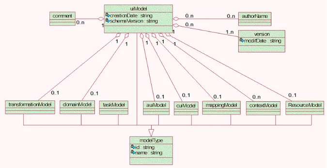
The user interface model in UsiXML consists of a list of component models (described above) in any order and any number. It doesn’t need to include one of each model component and there can be more than one of a particular kind of model component. It’s also composed by a creation date, a list of modification dates, a list of authors and a schema version.
UsiXML allows designers to apply a multi-path development of user interfaces. In this development paradigm, a user interface can be specified and produced at and from differ-ent, and possibly multiple, levels of abstraction while maintaining the mappings between these levels if required. Thus, the development process can be initiated from any level of abstraction and proceed towards obtaining one or many final user interfaces for various contexts of use at other levels of abstraction. In this way, the model-to-model transfor-mation, which is the cornerstone of Model-Driven Architecture (MDA), can be supported in multiple configurations, based on composition of three basic transformation types[11]: • abstraction, is the process of substitution of the input artefacts into more abstract
ones;
• reification, is the process of substitution of the input artefacts into more concrete ones;
• translation, is the process of substitution of the input artefacts aimed at a partic-ular context of use into others that are aimed for a different context.
Multi-path UI development is based on the Cameleon Reference Framework[3], which defines UI development steps for multi-context interactive applications. The development process with this framework is structured in four steps where each developments step is able to manipulate a set of artefacts in the form of models:
• Final UI (FUI): is the operational UI. Any UI running on a particular computing platform either by interpretation or by execution.
• Concrete UI (CUI): it’s a transformation of the abstract UI for a given context of use into Concrete Interaction Objects (CIOs). It defines widgets layout and interface navigation. The CUI abstracts a FUI into a UI definition that is independent of any computing platform. Although a CUI makes explicit the final appearance and style of a FUI, it is still a mockup that runs only within a particular environment. A CUI can also be considered as a reification of an AUI at the upper level and an abstraction of the FUI with respect to the platform.
• Abstract UI (AUI): defines interaction spaces by grouping subtasks according to various criteria, a navigation scheme between the interaction spaces and selects Abstract Interaction Objects (AIOs) for each concept so that they are independent of any modality. An AUI abstracts a CUI into a UI definition that is independent of any modality of interaction. An AUI can also be considered as a canonical expres-sion of the rendering of the domain concepts and tasks in a way that is independent from any modality of interaction. An AUI is considered as an abstraction of a CUI with respect to modality.
• Task and Domain (T&D): describe the various tasks to be carried out and the domain-oriented concepts as they are required by these tasks to be performed. These objects are considered as instances of classes representing the concepts manipulated. UsiXML is also very extensible. At the model level USIXML allows to define any kind of model. In this sense it is possible to instantiate any new model of the above mentioned classes. At meta-model level USIXML offers a modular structure which clearly segregates the models it describes. This facilitates the integration of new classes of models into UsiXML. The model and its concept is simply declared along with its relationships with other models. Rules exploiting this new model can be defined afterwards.
In conclusion, UsiXML solves every problem stated in [19]. UsiXML was designed for user interfaces, it’s not an adaptation of some modelling language that was meant for other use. It provides several classes of models with different abstraction levels so that every
part of the interface is specified. By allowing the application of multi-path development process, it makes sure that every specification is platform independent. Finally, it’s a flexible language, UsiXML provides mechanisms that can be used to extend and modify it’s models and transformation rules.
2.5
Discussion
The first tools in this chapter were Janus[2] and Its[28]. These tools represent the begin-ning of MDDUI and at the same time two different approaches to this subject. Developers using Janus will decrease the development time of their applications. This seems to be the main goal of the project. Because it only needs one input, the domain model, it doesn’t take a lot of effort to create a UI. Of course this also means that the generated UI won’t have the same quality as one built by hand (depending on the abilities of the developer) and this is the most criticized aspect of Janus. On the other hand, Its can produce high quality UI’s. But the amount of work necessary to build something is huge compared to Janus. Its also provides a way to divide work through the development team which is a very interesting feature because it facilitates the implementation of different development methodologies alongside this tool.
By analysing these two projects one can infer that MDD can be used with two objectives in mind:
1. to build low-cost prototypes of an application rapidly; 2. to enhance the quality of the final product.
Janus is clearly a tool that can be used to rapidly create a prototype of an application that can be used to communicate with customers or other stake holders. Its is aimed at building better applications with large teams.
In section 2.2 were introduced a couple of projects that use numeric optimization to generate UI’s. The first project was Gadget[6]. This is a framework that abstracts the programmer from the optimization itself. The problem with this project is that it’s not a complete solution. Developers still have to produce evaluations which can be a tricky subject because it’s not trivial to determine what properties make a user interface “good”. The second project, Supple[7], it’s more mature and complete. The objective behind Supple is to generate UI’s at run time that are optimal for people with special needs.
Although Gadget is meant to simplify numeric optimization of UI’s in a way that it could be used by any developer it still looks very complex to use this system.
Supple is a more complete system. It receives three types of input models: • one related to the domain;
• other related to the user;
• and other related to the platform it’s supposed to run on.
This makes Supple easier for developers but doesn’t give them much control of the final UI. The great advantage of this system its his capability to dynamically adapt to the needs of every user.
Section 2.3 covered the use of UI patterns in the process of modelling a UI. In this section IdealXML[14, 13] was looked in detail. IdealXML is a tool where designers can, using several graphical notations, specify Domain models, Task models, AUI models and map-ping models between them. IdealXML manipulates a pattern repository, where patterns are organized following a hierarchical structure. This enables the usage of patterns at design time.
Unfortunately, like in most projects in this field, IdealXML is an academic project and it’s not ready to be adopted by the industry.
Section 2.4 covered “Specification Languages”. This is the most important topic ap-proached on this chapter because the lack of a standard language to describe UI’s is one of the most setbacks on this field. In this section we’ve looked into three projects that are trying to solve this issue.
First we analysed UMLi [4]. UMLi is an extension to UML with support for interaction models. The second project was WISDOM [16]. Like UMLi, WISDOM provides an extension to UML in order to support interactive models.
The third project in this section was, UsiXML [11]. UsiXML is a UIDL based on the Cameleon reference framework[3]. UsiXML supports every step in the Cameleon frame-work. UsiXML is a little different from the first two ones because it doesn’t try to extend UML. UsiXML introduces it’s own set of models but reuses familiar notations, like UML for domain models and CTT for task models.
Both WISDOM and UsiXML, ship with an engineering method, with different approaches. WISDOM’s method focus on the development of the entire product while UsiXML is
fo-cused on the UI. Both methods have their advantages and disadvantages. But, if we’re looking for a standard tool that can be used by most organizations, UsiXML’s approach is more generic and therefore has better probability to find a place in the industry. UMLi doesn’t propose an engineering method. This project seems to be the less featured one. It reuses some of UML models to model interactive features, and only introduces a new notation for AUI models. This can play in favour of UMLi because it’s the easiest one to understand and it’s the project that would take the least effort to integrate in an organization’s workflow.
In conclusion, WISDOM and UsiXML are the most full-featured butUsiXML is more generic then WISDOM. UMLi is less featured but at the same time easier to integrate in an organization.
Trying to guess which of these projects has the most probability of becoming a standard is a difficult task. Although there is one more parameter that can call the tie off which
is community. UsiXML is building a large and strong community1 around it. Taking
all things into account, UsiXML shows the best probability of becoming a standard in MDDUI.
Chapter 3
UsiXML
In section 2.4.3 USer Interface eXtensible Mark-up Language (UsiXML) was referred as part of the state of the art. In this chapter this subject will be studied in more depth. The focus of this chapter will not be just UsiXML as a User Interface Description Language (UIDL) but the whole project behind it.
UsiXML’s specification, version 1.8, was released in February 14th, 2007. In April of 2009 was founded a consortium with the objective of lowering the total application costs and development time by adding versatile context driven capabilities to UsiXML that would bring it far beyond the state of the art, up to the achievement of its standardisation. The UsiXML consortium started with three main goals that would guide the entire
project. The first goal is the UsiXML “µ7” concept elicitation and promotion. The
µ7 concept means that it should be possible to specify a User Interface (UI) for an in-teractive application that should support device, platform, user, multi-linguality/culturality, multi-organisation, multicontext, or multi-modality capabilities. The second goal is the development of theUsiXML language and the Model Driven Devel-opment of User Interfaces (MDDUI) method. The UsiXML language should guarantee interoperability, reusability, and maintainability of interactive applications developed. For this reason UsiXML is an open eXtensible Mark-up Language (XML)-compliant standard UIDL. There should be models to cover every µ7 aspects. Finally, UsiXML should define a flexible methodological framework that accommodates various development paths as found in organisations and that can be tailored to their specific needs.
The third goal is to set up development tools and demonstration of the validity on ap-plications. There should be a suite of software tools that support the methodological
framework defined in the second goal that can be later integrated or connected to avail-able software environments. A UsiXML service will be defined and developed once so that this service can be deployed many times, especially for all environments requir-ing them to reduce the total cost of development. UsiXML will provide developers with various knowledge bases containing usability and accessibility guidelines that can be semi-automatically verified on any UsiXML-produced UI so as to guarantee a certain level of quality.
Section 3.1 provides a description of the UsiXML semantics. In section 3.2 refers to the UsiXML engineering method for developing UI’s.
3.1
UsiXML semantics
The core component of a user interface specified in UsiXML consists of a uiModel, which is itself decomposed into several models. Not all models should be included. Only those models which are required for the particular UI are included in a UsiXML file. Figure 3.1 shows the components of UsiXML in an Unified Modelling Language (UML) class diagram.
Figure 3.1: UsiXML specification as an UML class diagram.
The uiModel is the topmost superclass containing common features shared by all compo-nent models of a user interface. A uiModel may consist of a list of compocompo-nent models in