Repositório ISCTE-IUL
Deposited in Repositório ISCTE-IUL:
2018-06-07Deposited version:
Post-printPeer-review status of attached file:
Peer-reviewedCitation for published item:
Vasconcelos, F., Figueiredo, L., Almeida, A. & Ferreira, J. C. (2017). SMART sensor network: with Bluetooth low energy and CAN-BUS. In 2017 IEEE International Conference on Service Operations and Logistics, and Informatics, SOLI 2017. (pp. 217-223). Bari: IEEE.
Further information on publisher's website:
10.1109/SOLI.2017.8120997Publisher's copyright statement:
This is the peer reviewed version of the following article: Vasconcelos, F., Figueiredo, L., Almeida, A. & Ferreira, J. C. (2017). SMART sensor network: with Bluetooth low energy and CAN-BUS. In 2017 IEEE International Conference on Service Operations and Logistics, and Informatics, SOLI 2017. (pp. 217-223). Bari: IEEE., which has been published in final form at
https://dx.doi.org/10.1109/SOLI.2017.8120997. This article may be used for non-commercial purposes in accordance with the Publisher's Terms and Conditions for self-archiving.
Use policy
Creative Commons CC BY 4.0
The full-text may be used and/or reproduced, and given to third parties in any format or medium, without prior permission or charge, for personal research or study, educational, or not-for-profit purposes provided that:
• a full bibliographic reference is made to the original source • a link is made to the metadata record in the Repository • the full-text is not changed in any way
The full-text must not be sold in any format or medium without the formal permission of the copyright holders.
Serviços de Informação e Documentação, Instituto Universitário de Lisboa (ISCTE-IUL) Av. das Forças Armadas, Edifício II, 1649-026 Lisboa Portugal
Phone: +(351) 217 903 024 | e-mail: [email protected] https://repositorio.iscte-iul.pt
SMART Sensor Network
with Bluetooth Low Energy and CAN-BUS
Flávio Vasconcelos, Lino Figueiredo, Ana Almeida
GECAD Research Center Instituto Superior de Engenharia do Porto
Porto, Portugal
[email protected], [email protected], [email protected]
Joao C. Ferreira
Information Sciences, Technologies and Architecture Research Center Instituto Universitário de Lisboa
(ISCTE-IUL), Lisbon Portugal [email protected]
Abstract— This paper proposes a system to monitor, through the internet, the data of a logistics distribution truck. For this, it was implemented a reliable and flexible wireless sensor network with low energy consumption. The technology used for the radio system was Bluetooth Low Energy (BLE). Each node in the network contains one type of sensor. The sensors information together with GPS and On-Board Diagnostics (OBD) data collected by the central unit, and later transmitted to the cloud by GSM or Wi-Fi.
Keywords— Bluetooth Low Energy; Internet of Things; Wireless Sensor Network; Controller Area Network; Piconet; Cloud.
I. INTRODUCTION
Advances in the areas of micro processing, Micro-Electro-Mechanical Systems (MEMS) and wireless communication stimulate the development of sensory equipment that can be used in a variety of application areas. Representing a subclass of ad-hoc wireless networks, Wireless Sensors Networks (WSN) are considered the new generation of real-time embedded systems with limited computing, power and memory resources. These networks can have large numbers of wireless nodes (also known as motes [1]) and are projected to collect and transmit data.
Usually nodes have low processing power capability to increase their autonomy. The fact that they are portable require the use of batteries. The radio module is the largest wear factor of the battery at the time of data transmission. There are other factors, such as, acquisition time, active time of the microcontroller, that are also important factors. One of the biggest challenges in WSN is to create mechanisms for cooperation between the network nodes so that the network has the capability to solve problems efficiently.
This type of solution is widely used in several scenarios because it is a low-cost solution for many applications. Other factors that lead to the use of WSN are: self-organization, node mobility in the geographic space, autonomous operation, ability to withstand poor environmental conditions, scalability, ease of use, among others [2].
A. Background and Motivation
The implementation of reliable, fault-tolerant, and robust computational systems is difficult due to external factors that
cannot be controlled or predicted. With the advance of technology there is a need to create systems that can monitor a large area, but at a relatively low cost. To fill this gap, the development of microelectronics provides the development of components with increasingly smaller dimensions, lower prices, greater functional capacity and lower energy consumption. This trend makes it possible to develop more complex and economically viable applications [3].
B. Internet of Things
Internet of Things (IoT) can be defined as a network of small, low-cost, low-power electronic devices where communications occur without human intervention. Each device acts as a "smart node" on the network, detecting information and performing low-level signal processing to filter out noise signals and to reduce the bandwidth required for node-to-node communications. Finally, nodes send this information to the "cloud" in a secure way to protect, store and process data. Analysts expect IoT to grow to approximately 36 billion connected devices by 2020 [4]. Currently there are numerous applications for IoT of which the smart homes, wearables, among others stand out.
Smart home is the most searched IoT related subject on Google. In smart homes, you can turn on the air conditioning before you get home or turn off the lights after you have left home. It is also possible to unlock the doors to friends for temporary access, even when we are not at home. Smart homes are making life simpler and more convenient. Products associated with Smart Home are promised to save time, energy and money.
Another great subject is Wearables. Wearable devices contain sensors and software that collect data and information about users. This data is subsequently processed to extract a user profile. These devices mainly cover fitness, health and entertainment. The IoT prerequisite for wearable applications is to be highly energy efficient or ultra-low power and small [5].
In the industry there is Industrial Internet of Things (IIoT). It is to enable industrial engineering with sensors, software and large analytical data to create intelligent machines. The big goal behind IIOT is that, make machines smarter and more accurate and consistent than humans in data communication. This can help companies solve inefficiencies and problems more easily [6].
II. WIRELESS SENSOR NETWORK
A sensor network is characterized by the ability to monitor one or more variables of interest in a particular event, such as distance, direction, speed, humidity, wind speed, temperature, motion, vibration, light intensity, seismic activity, Weight, pressure, among others [8]. WSN are suitable for situations where a wired solution cannot be implemented and where instant access to information is desired. Nodes can move along with observed phenomenon. As an example of this, we have sensors that are placed on animals to observe their behavior.
In the following sections it will be presented some features of an WSN as well as some factors that determine or influence the implementation of an WSN, some applications and practical cases.
A. Characteristics
The WSN are quite comprehensive and dynamic. This high level of flexibility requires mechanisms with large adaptability. For this to happen, the cluster architecture is used [7]. Cluster by definition, in the computational area, is a system consisting of a set of computers or autonomous processing units interconnected in order to work together for a purpose [9]. Clusters are ideal for organizing large amounts of elements that are located in a large area, thus providing excellent flexibility. Usually in a WSN there are 3 types of elements [7]: 1) Slave; 2) Master; and 3) Sink.
The slave aims to collect data from the sensors and transmit this data to the network.
The master node has the function of monitoring all existing slave nodes. The great feature of these elements is the ability to cross data from various sensors. These nodes can receive a massive amount of information from their slaves which will cause a significant drop in network performance. This implies that the processing of data has to be optimized [10].
The sink node is an element that connects to another network with the WSN. In this way the sink is a very important element because if this node stops working, the whole network is incommunicable with the outside [7].
B. Aplications
WSN can be used for a wide range of applications from the most diverse areas such as agriculture, military, health, domestic applications, among others.
Smart Homes - When talking about sensor networks in homes, IoT is soon associated. It is very common to apply a smart network to home automation. It is very comfortable to receive notification that the lights in your house are still on when you leave your home. Another possibility is to allow easily monitor the house and control the locks of the doors, making the residence theft proof. The system can be configured to automatically lock the doors when you are leaving the house or unlock them when you are approaching the main entrance. It is possible to monitor any type of temperature increase in the house using thermostats. The hardware is placed in and around home, the nodes interact
with smartphones and define the appropriate applications based on their proximity to installed nodes [16].
Agriculture - Another large area where WSN is applied is in precision agriculture. With a WSN it increases efficiency, productivity and profitability, minimizing impacts on wildlife and the environment [17]. Real-time information provides a solid foundation for farmers' strategies.
Beckwith et al., Implemented a WSN in a vineyard. This network contained 65 nodes whose goal was to collect temperatures for six months. The information was used to analyze two important parameters in wine production: sum of heat and damages caused by frost [18].
Industry - The food industry should follow high quality standards in order to be competitive and to meet the needs of consumers. The quality of food products can change rapidly because they are subjected to a variety of hazards during production, transportation and storage, which compromises quality [19]. Perishable food products such as vegetables, fruits, meat or fish require refrigerated transports. Therefore, temperature is the most important factor when extending the useful life of this type of food. Studying and analyzing the temperature inside refrigeration rooms, containers and trucks is the main concern of the industry. The use of a WSN in refrigerated vehicles is a solution to end the lack of temperature information during the trip [19]. The vehicles contain a variety of sensors to detect, identify, record and communicate what happens during the journey in order to control the status of perishable goods in transport.
III. BLUETOOTH LOW ENERGY
Bluetooth is now an indispensable technology in a mobile phone, thus allowing mobile devices to communicate with each other over short distances. In particular, Bluetooth Low Energy (BLE) is essential for small mobile devices because it requires very little power to operate.
BLE main characteristics -The purpose of BLE is to create a new class of small devices, which only need to send or receive a small amount of data frequently. To maintain power consumption relatively low, BLE has a transmit power (0.01 to 10mW) lower than standard Bluetooth (100mW for Class 1 devices and 1mW for Class 3) [21]. The data is sent in the same way, but with a slower speed, the maximum of 100kbps. BLE devices can switch between standby mode and active mode faster than standard Bluetooth, thus saving energy, allowing small bursts of data to be transmitted.
Many more benefits are behind the BLE. Currently there is a huge market for the ultimate consumer, as is the case with fitness wristbands. To get an idea this is the most common use for BLE, 96% of fitness devices have BLE [22].
Compared with other wireless technologies, the rapid growth of BLE is relatively easy to explain. This growth is directly related to the evolution of smartphones, tablets and mobile communications. The adoption of BLE from the beginning was made by the two biggest market leaders in the area of smartphones: Apple and Samsung. The first smartphone
that makes use of BLE was the iPhone 4S, released in October 2011 [20]. Although the market for smartphones and tablets is perfectly mature, there is a need to create connectivity with the outside world.
BLE Stack - Like the classic Bluetooth [23], the stack of BLE is composed of 3 parts [24]: 1) Controller; 2) Host; and 3) Application. The controller is typically the physical device that can transmit and receive radio signals. The host is usually a software layer that manages how two or more devices communicate with each other. The application layer is the most superficial layer and is the one that contains the logic and the interface with the user. The architecture of this layer depends very much on the application for which it was developed.
Network topologies The typology of the BLE network is relatively simple. There are 2 scenarios:
1) piconet - In the piconet, one or more slaves are connected to a single master. To identify each slave separately, each slave is assigned a temporary 3 bit address to be used when it is active. This means piconet can have maximum 8 devices. This includes 1 master and 7 slave bluetooth devices.
2) scatternet - Scatternet is a network which at least is made by combining two or more piconets. In this network, the devices which act as master and slaves, for example, when a certain device in the piconet acts as master or a slave by participating with another piconet which also acts as a master or a slave (Fig. 1). Scatternet primarily acts as a bridge between different piconets [25].
Fig. 1 Scatternet network [25]
IV. SMARTBLESENSOR NETWORK
The main objective of this work is to implement a system to monitor, through the internet, several physical quantities in a vehicle. A local network based on BLE and CAN technologies is implemented, which will gather information from several sensors and control different actuators located in truck deliver. Also for tracking of goods. The solution incorporates sensors in a vehicle to collect data about the trip such as: inertial sensors, temperature sensors, light sensor, limit switches and others. The system also incorporates a CAN bus and a GPS to get more data about the trip. From the CAN bus it is possible to measure driving styles and monitor consumption [26]. The system architecture is very flexible since it allows to add or remove sensors easily. It is a low-power solution that allows to wirelessly transmit the information to the cloud. All this
information will be stored in the cloud for monitoring purposes.
A. Architecture and System Design
The proposed system, Fig. 2, is a system of up to 7 nodes, each one with a sensor to measure a physical quantity and/or actuator. After this information is captured, it is sent via wireless to the master node, which is responsible for receiving information from its slaves. The central module has a GPS to determine its location and an interface with the cloud, where it is possible to view data from any network sensor. The block called On-Board Diagnostics (OBD-II) is the CAN bus existing in cars. This network can provide a lot of information such as: instant speed information, engine speeds, etc [27]. This information is sent and stored in the cloud.
Fig. 2 System Architecture
Note that, currently the system is limited to 7 devices because it is a piconet topology, however, it can be transformed into a scatternet [7].
Slave Nodes - The proposed system has various slave nodes that have the capacity to measure various physical quantities such as: luminosity, temperature, atmospheric pressure, acceleration, etc. Each slave element in the network contains a SoC (System-on-a-Chip) nrf51822. This SoC is suited for Bluetooth low energy and 2.4GHz ultra low-power wireless applications. The SoC nrf51822 contains a 32-bit ARM Cortex M0 CPU with 256kB/128kB flash + 32kB/16kB RAM for improved application performance. It has several communication peripherals, namely Serial Peripheral Interface (SPI), Inter-Integrated Circuit (I2C) and Universal Asynchronous Receiver/Transmitter (UART). It also has 31 pins of General Purpose Input/Output (GPIO) and 10-bit
Analog Digital Converter (ADC). All these characteristics made this SoC the right choice considering performance, low energy and low cost [28]. The DS18B20 will be used to measure the temperature. This sensor operates with the OneWire protocol, allowing the connection of several sensors in a network. With this it is possible to acquire temperature data of several points in the physical space through only one pin. To quantify the brightness a Light Dependent Resistor (LDR) will be used. This is a resistive sensor, so a variation in brightness results in a variation in its resistance.
For this project it was chosen the MPU-6050 which is a chip that contains an accelerometer and a gyroscope together. It is displayed as a 6-axis low power MEMS sensor, 3-axis for the accelerometer and the remaining for the gyroscope. With a scale of up to 16g and 2000º/Sec [29].This sensor has I2C interface that allows data acquisition up to 400kHz in fast mode.
Master Node - The master node receives sensors information via wireless from the slave nodes and is always ready to respond to requests from the central unit. The task of this node is to gather all the information of its slaves, to send later to the central unit. Centralizing all the sensor information in the central unit. The hardware is pretty simple, this node only has a SoC nrf51822.
Central Unit - The central unit is the brain of the entire network. The function of this device is to gather all information from the sensors, GPS, information available on CAN-BUS (vehicle) and send it in a coordinated way to the cloud. Here we have a GPS sensor whose function is to determine the location periodically. The microcontroller that processes all this information is the STM32F103 [30]. The GPS module used is the uBlox NEO-6M. The choice of this module is due to the fact that it contains the UART protocol for communication [31] and also has the standard ISO 16750 [32].
A serial port is used to connect the microcontroller to the GSM or Wi-Fi module. This module is responsible for sending all information via wireless to the cloud. All the information related to the vehicle trip will be stored in the cloud and will be available in any place in the world.
a) b)
Fig. 3- a) slave node nrf51822 b) Master node STM32F103 [32]
Cloud - The Information of all elements in the network is sent to the cloud. This enables remote monitoring, and the configuration of the entire system. It is not the responsibility of this system to host the cloud.
B. Software
To explain the operation of the whole system it is presented a brief description of the software architecture.
Slave Nodes - The software for slave nodes always follows the same principle. In the Fig. 4 is presented a diagram where it is possible to see all main steps. For each node, there are different types of sensors, they use different communication protocols and therefore the microcontroller needs a peripheral that allows it to communicate with the sensor. This is the first step, initialize the necessary peripheral. In this step, the microcontroller pins are also configured for the outputs/inputs. Still here, the BLE stack, the services and other parameters necessary for the perfect operation of the BLE are initialized.
Fig. 4 Diagram of Software (Slave)
The next step represents the connection of the slave to the master, starting with the advertising mode and wait for the connection to be established.
Once gathered the sensor data, it is compared with the previous reading plus a threshold value, if the actual reading is bigger than the previous reading plus a threshold value, the slave transmits the data to the master otherwise it stars a new reading. it is also possible to define a sampling rate. Whenever the slave receives some information from the master node, it comes via BLE and this causes an interrupt service routine to be executed. At that time, the message is proceed and then the outputs updated.
Master Node - The software for the master is relatively simple (Fig. 5). In the first step the BLE stack and the peripheral UART are initialized. UART is the communication module used to exchange data between the master and the central unit. After all slaves are connected, the master waits for messages from the slaves. After receiving some information this will save the value and prepare the sending via UART. The reception of information is made by interruption. In this interruption is given an "ok" to send this same information by UART in the main cycle. This information goes to the central unit to be sent to the cloud.
Fig. 5 Diagram of software (master)
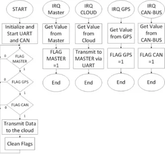
If the master receives information from the UART it means that some slave node output must be updated. After receiving the message, it is necessary to identify the target slave and the logical level, and then transmit the information to the slave. Central Unit -In the Fig. 6 it is possible to see the central unit diagram where it is described all the steps. Like the master and the slave nodes, the peripherals are also initialized, in this case the UART and CAN. UART is the module used to communicate with the GPS module and the CAN module is used to gathered information from the vehicle.
After initializing the peripherals, the central unit receives data from master node, the GPS and finally the CAN bus can provide detailed vehicle data or used to transmitted data using existing cable system in the vehicle or truck. The program main cycle will poll all data ready flags and then sends the data to the cloud.
Fig. 6 Diagram of software (Central)
V. URBAN DISTRIBUTION OF GOODS IN A CITY ENVIROMMENT
IoT is applied to track delivery process and to control drivers behavior based on the analyses of fuel consumption,
acceleration, breaking process, engine rotation. This proposed network allows the implementation of a low cost sensing because there is no need of cabling and sensors are available at low prices. It is possible to monitor temperature with special delivers, follow the goods and operator logistics can monitor their driver behavior at low cost solution. This delivers truck are becoming a part of the broader IoT logistics ecosystem that could transform trucking and the logistics industry. These trucks are becoming a mobile node in the IoT, real time connection between the delivers stakeholders (driver, sender, logistics operator and receiver). Optimization process can be performed in real time. Connected with high-speed cellular Internet data from sensors on trucks, dispatchers can measure real-time fuel efficiency, and how drivers operate their vehicles — do they brake too late, or waste diesel on lead-foot starts? Fleet management systems can recommend the optimal speed for a route [26].
Telematics sensors in trucks and multisensory tags on items transmit data on location, condition and whether a package has been opened. Sensors that measure the capacity of each load can provide additional insight into spare capacity in vehicles. The IoT data could then populate a central dashboard that focuses on identifying spare capacity on particular routes or destination pairs and analytics could recommend suggestions for consolidating and optimizing the route.
MoDe (Maintenance on Demand) is a EU-backed research project between Volvo, DHL and other partners sought to create a commercially viable truck that decides autonomously when and how it requires maintenance. The latest sensor technology has been incorporated at several points, such as oil systems and shock absorbers, to identify degradation or property damage. The data is then transmitted first to a central unit in the truck via a wireless network, then to a maintenance platform for analysis. The driver or maintenance teams are alerted to possible problems. [33]
VI. CONCLUSION
This paper presented an IoT system to collect data from vehicle that can be apply of the goods distribution process in a city, where there is always network connectivity at low prices. Allows the easy data collection from several sensors that can be implemented in a distribution truck to monitor in real time this process. IoT allows important payoffs for logistics operators and their business customers and end consumers by a real time deliver monitor process without big investments associated.
Also this network allows easy installation process because there is no need of cable and a diversity of data can be collected based on the type of sensor. This is part of academic research but there is a big potential of this solution of different commercial environments.
REFERENCES
[1] M. Leopold, “Sensor Network Motes :Portability & Performance,” no. December, pp. 1–123, 2007.
and Countermeasures,” vol. I, 2015.
[3] D. Culler, D. Estrin, and M. Srivastava, “Overview of sensor networks,” Computer (Long. Beach. Calif)., vol. 37, no. August, pp. 41–49, 2004.
[4] W. Bluetooth and S. Sub, “Wireless connectivity for IoT applications,” 2015.
[5] Ciara O’Brien, “Wearables: Samsung chases fitness fans with Gear Fit 2,” 2016. [Online]. Available:
http://www.irishtimes.com/business/technology/wearables-samsung-chases-fitness-fans-with-gear-fit-2-1.2763512. [Accessed: 04-May-2017].
[6] TIM HAWKINS, “An edge-to-cloud continuum: Inside GE Digital’s Predix Industrial Internet of Things platform | #theCUBE - SiliconANGLE,” Silicon Angle, 2016. [Online]. Available:
https://siliconangle.com/blog/2016/08/22/an-edge-to-cloud- continuum-inside-ge-digitals-predix-industrial-internet-of-things-platform-thecube/. [Accessed: 04-May-2017].
[7] I. F. Akyildiz, W. Su, Y. Sankarasubramaniam, and E. Cayirci, “Wireless sensor networks: a survey,” Comput. Networks, vol. 38, no. 4, pp. 393–422, 2002.
[8] D. Communication, Wireless Sensor and Actuator Networks Algorithms and Protocols for Scalable Coordination. Wiley, 2010.
[9] C. S. Yeo, R. Buyya, H. Pourreza, R. Eskicioglu, P. Graham, and F. Sommers, “Cluster Computing: Performance, High-Availability, and High-Throughput Processing on a Network of Computers,” Handb. Nature-Inspired Innov. Comput. Integr. Class.
Model. with Emerg. Technol., pp. 521–551, 2006.
[10] T. Schoellhammer, B. Greenstein, and D. Estrin, “Hyper: A Routing Protocol To Support Mobile Users of Sensor Networks,” Cent.
Embed. Netw. Sens., Jan. 2006.
[11] M. Staroswiecki, “On fault tolerant estimation in sensor networks,”
… Eur. Control Conf. Cambridge, UK, no. 5, pp. 1–6, 2003.
[12] G. Hoblos, M. Staroswiecki, and A. Aitouche, “Optimal design of fault tolerant sensor networks,” IEEE Int. Conf. Control Appl., pp. 467–472, 2000.
[13] E. Shih, S.-H. Cho, N. Ickes, R. Min, A. Sinha, A. Wang, and A. Chandrakasan, “Physical layer driven protocol and algorithm design for energy-efficient wireless sensor networks,” Proc. 7th Annu. Int.
Conf. Mob. Comput. Netw. - MobiCom ’01, pp. 272–287, 2001.
[14] A. Woo and D. E. Culler, “A transmission control scheme for media access in sensor networks,” Proc. ACM 9th Int. Conf. Mob. Comput.
Netw., pp. 211–235, 2001.
[15] J. Chilo, C. Karlsson, P. Ängskog, and P. Stenumgaard, “EMI disruptive effect on wireless industrial communication systems in a paper plant,” IEEE Int. Symp. Electromagn. Compat., pp. 221–224, 2009.
[16] Shubhi Mittal, “IoT and Home Automation: How Beacons are Changing the Game | Beaconstac,” 2015. [Online]. Available: https://blog.beaconstac.com/2015/11/iot-and-home-automation-how-beacons-are-changing-the-game/. [Accessed: 02-May-2017]. [17] H. R. Bogena, M. Herbst, J. a. Huisman, U. Rosenbaum, a.
Weuthen, and H. Vereecken, “Potential of Wireless Sensor Networks for Measuring Soil Water Content Variability,” Vadose
Zo. J., vol. 9, no. 4, p. 1002, 2010.
[18] R. Beckwith, D. Teibel, and P. Bowen, “Report from the field: results from an agricultural wireless sensor network,” 29th Annu.
IEEE Int. Conf. Local Comput. Networks, pp. 471–478, 2004.
[19] Q. Shan, Y. Liu, G. Prosser, and D. Brown, “Wireless intelligent sensor networks for refrigerated vehicle,” Proc. IEEE 6th Circuits
Syst. Symp. Emerg. Technol. Front. Mob. Wirel. Commun. (IEEE Cat. No.04EX710), vol. 2, pp. 525–528, 2004.
[20] T. O’Brien, “iPhone 4S claims title of first Bluetooth 4.0 smartphone, ready to stream data from your cat,” engadget, 2011. [Online]. Available: http://www.engadget.com/2011/10/12/iphone-4s-claims-title-of-first-bluetooth-4-0-smartphone-ready/. [Accessed: 02-Mar-2016].
[21] Bluetooth Special Interest Group, “Specification of the Bluetooth System Covered Core Package Version 4.0,” vol. 0, no. June, p. 2302, 2010.
[22] M. Ryan, “Outsmarting Bluetooth Smart,” CanSecWest, 2014. [23] A. . Fallis, “Final Report on the Inter-Agency Workshop on
Research Issues for Smart Environments,” J. Chem. Inf. Model., vol. 53, no. 9, pp. 1689–1699, 2013.
[24] R. Heydon and N. Hunn, “Bluetooth Low Energy,” … , Bluetooth
SIG https//www. bluetooth. org/ …, 2012.
[25] RF Wireless World, “Piconet vs Scatternet-Difference between Piconet,Scatternet,” 2015. [Online]. Available: http://www.rfwireless-world.com/Terminology/difference-between-piconet-and-scatternet-in-bluetooth.html. [Accessed: 06-May-2017]. [26] J. Ferreira, J. Almeida, A. Silva. The Impact of Driving Styles on
Fuel Consumption: A Data Warehouse and Data Mining based Discovery Process, IEEE Transactions on Intelligent Transportation Systems Magazine on Intelligent Transportation Systems in March 2015. DOI (identifier) 10.1109/TITS.2015.2414663
[27] SAE Standard, “SAE J1979: E/E Diagnostic Test Modes,” SAE
Stand., vol. 552, no. 1, 2002.
[28] Waveshare, “Core51822 - Waveshare Wiki,” 2016. [Online]. Available: http://www.waveshare.com/wiki/Core51822. [Accessed: 06-May-2017].
[29] Dynastream Innovations Inc., “ANT Message Protocol and Usage,” pp. 1–134, 2013.
[30] O. Rtc, A. Autonomous, H. Gps, A. Online, A. Offline, O. M. A. Supl, G. P. S. Solution, T. Neo-, T. Ddc, A. Neo-, M. Type, and S. Interfaces, “NEO-6 series,” pp. 6–7.
[31] P. Code, “International Standard ISO 16750,” Shock, vol. 2003, pp. 1–8, 2002.
[32] Roger Clark, “STM32F103 and Maple / Maple Mini with Arduino 1.5.x IDE | Roger Clark,” 2016. [Online]. Available: http://www.rogerclark.net/stm32f103-and-maple-maple-mini-with-arduino-1-5-x-ide/. [Accessed: 06-May-2017].
[33] “FP7 - Maintenance on Demand - MoDe.” [Online]. Available: http://fp7-mode.eu/. [Accessed: 08-Jul-2017]
![Fig. 1 Scatternet network [25]](https://thumb-eu.123doks.com/thumbv2/123dok_br/19230366.967063/4.892.518.799.338.766/fig-scatternet-network.webp)