IMPACT STRENGTH OF CARBON/EPOXY LAMINATES WITH HOLES
R.A.M. Santos1(*), P.N.B. Reis2, M.J. Santos3, ´C.A.C.P. Coelho4
1 Depart. of Aerospace Sciences, University of Beira Interior, Covilhã, Portugal
2 Dept. of Electromechanical Engineering, University of Beira Interior, Covilhã, Portugal 3
CEMUC, Depart. of Electrical and Computers Engineering, University of Coimbra, Coimbra, Portugal 4 ESTA, Escola Superior de Tecnologia de Abrantes, Instituto Politécnico de Tomar, Tomar, Portugal (*)Email: [email protected]
ABSTRACT
The effect of non-perpendicular holes on the impact strength of carbon fibre/epoxy composite laminates was studied. In order to understand this effect, flexural tests were also performed to evaluate the bending strength. It was possible to conclude that higher angles promote a decrease of the bending loads. In terms of impact tests, higher angles promote a decrease of the maximum impact load, impact bending stiffness and elastic recuperation. An opposite tendency occurs in terms of maximum displacement.
Keywords: Composite Laminates, Impact tests, Mechanical behaviour.
INTRODUCTION
It is recognised that, in many cases, the structural application of composite materials requires open holes to allow the access of electric wires, hydraulic pipes, assembly and/or maintenance activities and often time these hole are required to be angled. In this context, damage will initiate and grow from these notches, due to the stress/strain concentrations, with consequent lower strength and/or life.
If the effect of holes or cut-outs has been studied extensively in terms of tensile and compressive behaviour, there are very few works related to impacts at low velocity [1]. This mode of loading is very dangerous, because it promotes damages very difficult to detect [2] and, simultaneously, the residual properties of the composite materials are significantly affected [3-4].
Green et al. [5] reported the first results of an experimental and numerical study to determine the additional damage arising from the presence of holes. They are responsible by the matrix cracks that occur in the lower lamina, and these multiple cracks can extend from the region directly below the impact to the edge of the holes. In some circumstances, further cracks can emanate from the far side of the holes. According to Luo [6], the damage consists basically in delamination associated with matrix crack, but with absence of fibre breakage. Two parallel matrix cracks appear between the impact point and the hole. One crack initiates at the point of impact and propagates towards the hole whereas the other crack initiates near the hole edge and propagates towards the impact centre. These cracks can be initiated by either tension or shear or a combination of both. On the other hand, when the laminates contain two holes, the delaminations initiate at the interface from the inner free edges of the holes and with time, they meet each other forming a big delamination area [1]. Amaro et al. [7] found that the failure morphology is altered by the presence of holes, confirming a complex damage mechanism. The main goal of the present work is to analyse the effect of non-perpendicular holes on the impact strength of carbon fibre/epoxy composite laminates. The results will be discussed in terms of load-time, load-displacement, energy-time diagrams and evaluation of the damage.
MATERIAL AND EXPERIMENTAL PROCEDURE
CFRP were made from carbon Prepreg, TEXIPREG® HS 160 REM (provided by SEAL, Legnano, Italy). The CFRP laminates were prepared with sixteen layers, and a stacking sequence of [04,904]s, using the autoclave/vacuum-bag moulding process in agreement with the manufacturer recommendations. The processing setup consisted of several steps: making the hermetic bag and applying a 0.05 MPa vacuum; heating up to 125º C at a 3–5º C/min rate; applying a pressure of 5 bar when a temperature of 120-125º C is reached; maintaining pressure and temperature for about 150 min; cooling down to room temperature maintaining pressure and finally getting the part out from the mould. The plates were manufactured in a useful size of 300x300x2.5 mm3. The quality control was performed by C-Scan, to evaluate the eventual presence of defects resulting from the manufacturing process.
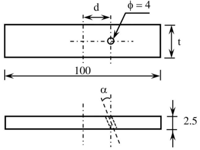
Figure 1 shows the geometry of the CFRP specimens used in the flexural and impact tests. These specimens were obtained from the thin plates and the dimensions are, respectively, 100×20×2.5 mm3 and 100×100×2.5 mm3. Angles of 0º, 10º and 20º, with the vertical axis, and diameter of 4 mm were obtained with a special drill for this effect. After drilled, the specimens were evaluated again by C-Scan to verify if any defect was introduced.
Three-point bending tests were performed with a span of 50 mm and at a displacement rate of 3 mm/min. All tests were carried out at room temperature and five specimens were tested for each condition according with the ASTM D7264/D7264M–15 standards. Low-velocity impact tests were performed using a drop weight-testing machine, IMATEK-IM10. An impactor with a diameter of 10 mm and mass of 2.827 kg was used. The tests were performed on square section samples of 75x75 mm and the impactor stroke at the centre of the samples obtained by centrally supporting the 100x100 mm specimens. The impact energy used in the tests was 3 J.
Figure 1. Geometry of the CFRP samples, dimensions in mm (t = 20 mm for flexural tests, t = 100 mm for impact tests; d = 10 mm; = 0º, 10º and 20º).
RESULTS
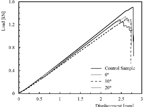
Figure 2 shows representative curves of the bending load versus flexural displacement for the angles studied. A nearly brittle behaviour can be observed for all angles, with a linear region up
2.5 100 t d
values and the bands represent, respectively, the maximum and minimum values obtained from the five tests. For laminates without holes (control samples) an average maximum load of 1535 N was found, and this value tends to decrease with the angle of the hole. For example, when the angle is 0º the average maximum load decreases around 12.1%, comparatively to the control samples, but, when the angle is 20º this value is about 15.6% lower.
Figure 2. Load-displacement curves for different angles.
Given that for the angles studied the difference of the average maximum load between the 0º and 10º angle was around 0.6%, the last one was removed from the study of the impact strength. Figure 4. shows the force-time and energy-time curves, which represent the typical behaviour occurred for all laminates and agree with the bibliography. These curves contain oscillations that are consequence of the vibrations promoted by the samples.
Figure 4. Load-time and energy-time curves for control samples and samples with holes with angles of 20º.
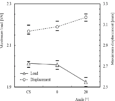
Figure 5. Maximum load and maximum displacement versus angle of the hole with the vertical axis for the impact tests.
Figure 5 shows the results in terms of maximum load and maximum displacement. For the CS an average maximum load of 2014 N was obtained. This value was 2.3% lower for the hole with a 0º angle and 7% lower for the 20º hole. The decrease of the load with an increasing of the angle can be explained by the damage mechanisms presented in Figure 6.
The impact bending stiffness has been known as an important property in assessing the damage resistance of a composite. Using the load-displacement curves for the first impact, the slope of the linear regression of the ascending section of the load–displacement curve, up to the maximum load and displacement, is the bending stiffness.
Similarly, the energy-time curve can be used to obtain the elastic recuperation (Er) (or elastic energy), which is the amount of energy that is converted from the kinetic energy of the drop weight by the plate to return to its initial shape and make the weight rebound. The elastic recuperation can be obtained by taking the maximum energy of the curve (Emax), and the average baseline energy, which is the energy of the more or less constant portion of the energy curve (Eab).
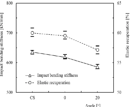
Figure 7 presents the impact bending stiffness (IBS) and the elastic recuperation. As shown, both variables decrease with an increase of the hole angle. For control samples, the average IBS is 635 kN/mm and this value is 2.6% and 7.9% lower for 0º and 20º, respectively. On the other hand, the elastic recuperation for the control samples is about 60%, and a decrease of 0.8% for 0º holes and 4.7% for 20º holes was noted. This decrease in elastic recuperation is necessarily accompanied by an increase in absorbed energy, which agrees with the previous results. Therefore, it is evident the effects of the angle on the impact strength.
Figure 6. C-scan pictures of the samples: (a) Control Sample; (b) Holes of 0º; (c) Holes of 20º hole.
Figure 7. IBS and elastic recuperation versus angle of the hole.
CONCLUSION
This work studied the effect of non-perpendicular holes on the impact strength of carbon fibre/epoxy composite laminates. It was possible to conclude that higher angles promote a decrease of the bending loads as well as the impact strength. Higher angles promote a decrease of the maximum impact load, impact bending stiffness and elastic recuperation in terms of impact strength. An opposite tendency occurs in terms of maximum displacement.
REFERENCES
[1] Roy T, Chakraborty D. Delamination in FRP laminates with holes under transverse impact. Mater Des 2008; 29: 124–32.
[2] Amaro A.M., Reis P.N.B., de Moura M.F.S.F. and Santos J.B. Damage Detection on Laminated Composite Materials Using Several NDT Techniques. Insight 2012; 54: 14-20. [3] Amaro AM, de Moura MFSF, Reis PNB. Residual strength after low velocity impact in
carbon–epoxy laminates. Mater Sci Forum 2006; 514–516: 624-8.
[4] Reis PNB, Ferreira JAM, Antunes FV, Richardson MOW. Effect of interlayer delamination on mechanical behavior of carbon/epoxy laminates. J Compos Mater 2009; 43: 2609-21. [5] Green ER, Morrison CJ, Luo RK. Simulation and experimental investigation of impact
damage in composite plates with holes. J Compos Mater 2000; 34: 502-21.
[6] Luo RK. The evaluation of impact damage in a composite plate with a hole. Compos Sci Technol 2000; 60: 49-58.
[7] Amaro AM., Reis PNB, de Moura MFSF; Neto MA. Influence of open holes on composites delamination induced by low velocity impact loads. Compos Struct 2013; 97: 239-44.