José Miguel Ferreira Preto Marques Luzio
Mestre em Engenharia Electrotécnica e de ComputadoresHigh Efficiency Transmission Techniques for
Broadband Wireless Systems
Dissertação para obtenção do Grau de
Doutor em Engenharia Electrotécnica e de Computadores
Orientador:
Rui Miguel Henriques Dias Morgado Dinis,
Prof. Auxiliar com Agregação,
Universidade Nova de Lisboa
Co-orientador:
Paulo Miguel de Araújo Borges Montezuma de Carvalho,
Prof. Auxiliar, Universidade Nova de Lisboa
Júri:
Presidente: Doutor Luips M. Camarinha Matos Vogais: Doutor Adão Paulo Soares da Silva
Doutor Marco Alexandre Cravo Gomes Doutor Luis Filipe Lourenço Bernardo Doutor João Carlos Marques Silva
High Efficiency Transmission Techniques for Broadband Wireless Systems
Copyright cJosé Miguel Ferreira Preto Marques Luzio, Faculdade de Ciências e Tecnolo-gia, Universidade Nova de Lisboa
Para mim.
A
CKNOWLEDGEMENTS
I would like to thank professor Rui Dinis and Paulo Montezuma the opportunity to make this PhD, all the support of UNINOVA and IT, as well as FCT for the four year PhD grant. The time spent throughout this PhD gave me the opportunity to grow as a scientific researcher and as a human being.
I would like tho thank my family for the unconditional support. For being the anchor that was always there to support me when life requested it.
Finally, a great many thanks to my personal friends, for being most present in this period of my life.
A
BSTRACT
Future broadband wireless systems are expected to cope with severely time dispersive channels, due to multi-path signal propagation between the transmitter and the receiver while having high power and spectral efficiency. Thus, advanced Frequency Domain Equalization techniques are required. The implementation complexity in mobile terminals should be as low as possible to achieve highest possible efficiency. Therefore, most of the signal processing requirements will be shifted to the base station and we will employ signals compatible with an efficient, grossly nonlinear power amplification. For this reason, we will consider offset modulation signals with quasi-constant envelope and develop receivers that will obtain good BER performance. However, these signals require a bandwidth significantly above the Nyquist rate, which can be reduced by an overlap of different frequency channels.
R
ESUMO
Os futuros sistemas de banda larga sem fios devem suportar canais com distorção temporal severa, devido aos múltiplos caminhos de propagação do sinal entre o transmissor e o receptor enquanto apresentam alta eficiência espectral e de potência. Portanto, são necessárias técnicas avançadas de igualização no domínio da frequência. Uma vez que a complexidade de implementação dos terminais móveis deve ser tão baixa quanto possível, vamos transferir a maioria das exigências de processamento de sinal para a estação base e vamos usar sinais compatíveis com uma amplificação não linear eficiente. Por este motivo, vamos considerar modulações com desfasamento temportal que tenham uma envolvente constante ou praticamente constante e desenvolver receptores que consigam obter bons desempenhos. No entanto, estes sinais requerem uma largura de banda significativamente superior à de Nyquist, pelo que vamos também considerar a sobreposição de canais no domínio da frequência para reduzir a largura de banda necessária.
C
ONTENTS
Contents xiii
List of Figures xvii
List of Tables xxi
1 Introduction 1
1.1 Research Question, Hypothesis and Approach . . . 2
1.2 Outline . . . 2
1.3 Major Contributions . . . 3
2 Literature Review 5 2.1 Introduction . . . 5
2.2 Interference Types. . . 5
2.3 Bit Modulation . . . 8
2.3.1 Binary Phase Shift Keying . . . 8
2.3.2 Quaternary Phase Shift Keying . . . 9
2.3.3 Offset Quaternary Phase Shift Keying . . . 9
2.3.4 M-ary Phase Shift Keying . . . 10
2.3.5 Multi-level Constellations . . . 11
2.3.6 Hierarchic Constellations . . . 11
2.3.7 Decomposition of M-ary Offset Quadrature Amplitude Modula-tion (M2-OQAM) into several Offset Quaternary Phase Shift Key-ing (OQPSK) components . . . 12
2.4 Support Pulses. . . 13
2.4.1 Raised Cosine Pulses . . . 14
2.4.2 Minimum Shift Keying Pulses (half sinusoid) . . . 14
2.5 Envelope Fluctuations and Dynamic Range . . . 16
2.6 Block Transmission Techniques . . . 17
2.6.1 Single Carrier with Frequency Domain Equalization. . . 19
2.7 Equalization Methods . . . 20
2.7.1 Linear Frequency Domain Equalization . . . 22
CONTENTS
2.7.3 Iterative Block Decision Feedback Equalizer . . . 24
2.7.4 Comparison between methods . . . 25
2.8 The Iterative Block Decision Feedback Equalizer . . . 25
2.8.1 Definition . . . 25
2.8.2 Computation of the Receiver Parameters for Iterative Block Decision Feedback Equalizer (IB-DFE) . . . 26
2.8.3 IB-DFE with soft decisions . . . 29
3 FDE Receiver designs for offset modulations 31 3.1 Introduction . . . 31
3.2 Linear and Iterative Frequency Domain Equalization (FDE) Designs with Oversampling . . . 33
3.2.1 FDE for Quaternary Phase Shift Keying (QPSK) Schemes . . . 33
3.2.2 Multiplicity in OQPSK Signals . . . 36
3.3 Linear FDE without In-phase Quadrature Interference (IQI) . . . 37
3.3.1 Method I . . . 38
3.3.2 Method II . . . 39
3.3.3 Method III . . . 41
3.3.4 Performance Results . . . 43
3.4 Linear FDE with Reduced Overall Residual Interference . . . 44
3.5 Iterative FDE with IQI Cancellation . . . 46
3.6 Performance Results with Multiple Unbalanced Nonlinear Amplifiers . . 49
3.6.1 Unbalanced system description . . . 51
3.6.2 Performance Results . . . 53
3.7 Computational Complexity . . . 53
3.7.1 Linear method . . . 53
3.7.2 Iterative method . . . 54
3.8 Conclusions and Final Remarks . . . 54
4 Pragmatic Receiver Designs for Offset Modulations 57 4.1 Introduction . . . 57
4.2 Offset QAM Signals . . . 58
4.2.1 Non-offset Modulations . . . 60
4.2.2 Offset Modulations . . . 61
4.3 Linear FDE Design for OQAM . . . 62
4.3.1 Conventional FDE . . . 63
4.3.2 Interference minimization FDE . . . 64
4.3.3 Minimum-band FDE . . . 65
4.3.4 Full-band FDE . . . 66
4.4 Performance Results for Linear Equalization . . . 68
4.5 Iterative FDE design . . . 69
CONTENTS
4.5.1 Iterative FDE with IQI cancellation . . . 69
4.5.2 Proposed Iterative Receiver . . . 71
4.5.3 Feedback Data Symbols . . . 72
4.6 Performance Results for Iterative Equalization . . . 73
4.7 Computational Complexity . . . 75
4.8 Conclusions . . . 76
5 Multiple User Receiver Designs For Offset Modulations 77 5.1 Introduction . . . 77
5.2 Receiver design for strong ACI levels . . . 78
5.2.1 System Description . . . 78
5.2.2 Parallel FDE Design with ACI and IQI Cancellation . . . 81
5.2.3 Computation of Receiver Parameters . . . 83
5.2.4 Performance Results . . . 86
5.2.5 Conclusions . . . 88
5.3 Receiver design for strong CCI levels . . . 88
5.3.1 System Description . . . 89
5.3.2 Low Complexity Parallel FDE Design . . . 92
5.3.3 Feedback Data Symbols . . . 94
5.3.4 Computation of Receiver Parameters . . . 95
5.3.5 Performance Results . . . 96
5.3.6 Conclusions . . . 97
6 Conclusions 99 6.1 Synthesis and Final Remarks . . . 99
6.2 Future Work . . . 99
L
IST OF
F
IGURES
2.1 InterSymbol Interference. . . 6
2.2 In-phase Quadrature Interference. . . 7
2.3 Adjacent-Channel Interference. . . 7
2.4 Co-Channel Interference. . . 8
2.5 Binary Phase Shift Keying (BPSK) waveform. . . 9
2.6 QPSK signal constellation (left) and OQPSK signal constellation (right). . . . 10
2.7 M-ary PSK signal constellation. . . 10
2.8 Quadrature Amplitude Modulation (QAM) and Offset Quadrature Amplitude Modulation (OQAM) signal constellations. . . 12
2.9 Decomposition of M2-OQAM for highly nonlinear amplification. . . 13
2.10 Raised cosine with different roll-off factors. Frequency spectrum (left) and time domain pulse (right). . . 15
2.11 Half sinusoid support pulse. Frequency spectrum (left) and time domain pulse (right). . . 15
2.12 IQ Diagrams for QPSK and OQPSK signals with raised cosine support pulses with different roll off factors. . . 16
2.13 IQ Diagrams for 16-QAM and 16-OQAM signals with raised cosine support pulses with different roll off factors. . . 17
2.14 Single Carrier with Frequency Domain Equalization (SC-FDE) and Orthogonal Frequency Division Multiplexing (OFDM) interoperability [Fal+02]. . . 18
2.15 Cyclic Prefix. . . 20
2.16 SC-FDE Transmitter (Tx block is detailed in Figure 2.17). . . 21
2.17 Tx Block. . . 21
2.18 SC-FDE Receiver with linear equalization (Rx block is detailed in Figure 2.19). 22 2.19 Rx Block. . . 22
2.20 Hybrid time-frequency Decision feedback equalization (DFE). . . 24
2.21 IB-DFE receiver . . . 25
3.1 Frequency-domain multiplicity in QPSK (up) and OQPSK (down) signals. . . 34
3.2 Symmetry groups for method I. . . 38
3.3 Symmetry and multiplicity groups for method II. . . 40
LIST OFFIGURES
3.5 BER for linear FDE. . . 44
3.6 SIRISI, SIRIQI and total Signal to Interference Ratio (SIR) versusλclip. . . . . . 46
3.7 λclip impact on the Bit Error Rate (BER) performance of a linear FDE. . . 47
3.8 BER performance of OQPSK with different linear FDE receivers. . . 48
3.9 BER performance of 16-OQAM with different linear FDE receivers. . . 49
3.10 Proposed Iterative Receiver Structure. . . 50
3.11 BER performance of OQPSK with iterative FDE receivers.. . . 51
3.12 BER performance of 16-OQAM with iterative FDE receivers. . . 52
3.13 BER performance versus∆θfor the four iteration with anEb/N0of 14 and 18dB. 54 3.14 BER performance versus∆G2for the four iteration with anEb/N0of 14 and 18dB. . . 55
3.15 BER performance versusEb/N0for∆θ =0, 0.1 and 0.2 rad. . . 56
3.16 BER performance versusEb/N0for∆G2=1, 1.1 and 1.2. . . 56
4.1 Data symbols’ oversampling (regular data symbols in the left, oversampled data symbols in the right). . . 60
4.2 Frequency data symbols block oversampling (regular data symbols in the left, oversampled data symbols in the right). . . 61
4.3 Overall channel impulse response (H(kJ)), channel impulse response ( ˘Hk(J)) and adopted pulse shape (R(kJ)) for N=64 andJ =8. . . 63
4.4 BER performance for QPSK and OQPSK with conventional FDE. . . 64
4.5 Linear frequency domain equalization.. . . 65
4.6 Frequency spectrum of raised cosine support pulse (left) and BER performance vs.Eb/N0for conventional FDE using raised cosine support pulses (right), for differentβ(roll-off) factors. . . 66
4.7 Frequency spectrum of Hk(J), H(kMB)(J) (up) and R(kJ), R(kMB)(J) (down) for an MSK support pulse.. . . 67
4.8 BER performance versusEb/N0for a 16-OQAM constellation. . . 69
4.9 BER performance versusEb/N0for a 64-OQAM constellation. . . 70
4.10 Regular Iterative Receiver Structure. . . 71
4.11 Proposed Iterative Receiver Structure. . . 72
4.12 BER performance versusEb/N0for 16-OQAM constellation for 4 iterations. . 74
4.13 BER performance versusEb/N0for 64-OQAM constellation for 4 iterations. . 75
4.14 BER performance versus Eb/N0 for Non-uniform 64-OQAM constellation (4;1;1/4) for linear and iterative (4 iterations) equalization. . . 76
5.1 System with strong Adjacent-Channel Interference (ACI) levels . . . 79
5.2 BER performance for QPSK and OQPSK with raised cosine (β = 1) support pulse and conventional FDE. . . 80
5.3 Proposed receiver structure. . . 81
LIST OFFIGURES
5.4 Frequency spectrum of Fk(,iu)and Hk,u.Ak,u forU = 3, a noise-free flat-fading
channel and a raised cosine support pulse with roll-off = 1. . . 83
5.5 Frequency spectrum of raised cosine (dashed blue line) and Minimum Shift Keying (MSK) with Gaussian filtering (red line) support pulses. . . 87
5.6 Frequency overlap of three different users: raised cosine (up) and MSK with Gaussian filtering (down). . . 88
5.7 Frequency spectrum of Fk(,iu) forU = 3,B = 2/Ts and a frequency selective fading channel. . . 89
5.8 BER performance RC1 . . . 90
5.9 BER performance XT . . . 91
5.10 Frequency data symbols block with offset and oversampling.. . . 91
5.11 Regular data symbols (right) and oversampled offset data symbols’ (right). . 92
5.12 Proposed receiver structure. . . 93
5.13 Power spectral density of a data blocks from each user and of MSK support pulses. . . 97
L
IST OF
T
ABLES
L
IST OF
A
CRONYMS
3GPP-LTE Third Generation Partnership Project - Long Term Evolution
ACI Adjacent-Channel Interference
BER Bit Error Rate
BiHDFE Bidirectional Hybrid Decision Feedback Equalizer
BPSK Binary Phase Shift Keying
BS Base Station
CCI Co-Channel Interference
CDMA Code Division Multiple Access
CI Conducted Interference
CP Cyclic Prefix
CPM Continuous Phase Modulation
DFE Decision feedback equalization
DFT Discrete Fourier Transform
ELHDFE ExtensionLess Hybrid Decision Feedback Equalizer
EMI Electromagnetic Interference
FDE Frequency Domain Equalization
FDMA Frequency Division Multiple Access
FFT Fast Fourier Transform
FSK Frequency Shift Keying
FT Fourier Transform
GMSK Gaussian Minimum Shift Keying
LIST OF ACRONYMS
HDFE Hybrid Decision Feedback Equalizer
HDFE-NP Hybrid Decision Feedback Equalizer with Noise Predictor
HPB High Protected Bit
I In-phase
IB-DFE Iterative Block Decision Feedback Equalizer
IB-DFE Iterative Block Decision Feedback Equalizer
IBI Inter Block Interference
IDFT Inverse Discrete Fourier Transform
ICI Inter-Carrier Interference
IFFT Inverse Fast Fourier Transform
IQI In-phase Quadrature Interference
ISI InterSymbol Interference
LPB Low Protected Bits
MFB Matched Filter Bound
MMSE Minimum Mean Square Error
MPB Medium Protected Bit
MSK Minimum Shift Keying
MT Mobile Terminal
MF-TDMA Multi-Frequency-Time Division Multiple Access
M-PSK M-ary Phase Shift Keying
M2-OQAM M-ary Offset Quadrature Amplitude Modulation
M2-QAM M-ary Quadrature Amplitude Modulation
OFDM Orthogonal Frequency Division Multiplexing
OQAM Offset Quadrature Amplitude Modulation
OQPSK Offset Quaternary Phase Shift Keying
PAM Pulse Amplitude Modulation
PAPR Peak-to-Average Power Ratio
PIC Parallel Interference Cancellation
PMEPR Peak-to-Mean Envelope Power Ratio
PN Pseudo Noise
PSK Phase Shift Keying
Q Quadrature
QAM Quadrature Amplitude Modulation
QPSK Quaternary Phase Shift Keying
SC Single Carrier
SCM Single Carrier Modulation
SC-FDE Single Carrier with Frequency Domain Equalization
SC-FDMA Single Carrier with Frequency Division Multiple Access
SIC Serial Iterative Cancellation
SIR Signal to Interference Ratio
SISO Soft Input Soft Output
SNIR Signal to Noise plus Interference Ratio
SNR Signal to Noise Ratio
TDDFE Time Domain Decision Feedback Equalizer
TCM Trellis Coded Modulation
UWB Ultra Wideband
WINNER Wireless INitiative NEw Radio
L
IST OF
S
YMBOLS
General Symbols
an nthtime-domain data symbol aI
n real part ofan(“in-phase bit”)
aQn imaginary part ofan(“quadrature bit”) a(J)n oversampled version ofan
aI(J)n real part ofa(J)n (oversampled “in-phase bit”)
aQ(J)n imaginary part ofa(J)n (oversampled “quadrature bit”)
e
an estimate ofanat the equalizer output
ea(i)n theith iteration ofean
eaI
n real part ofean
eaQn imaginary part ofean
ea(J)n oversampled version ofean
e
aI(J)n real part ofea(J)n
e
aQ(J)n imaginary part ofea(J)n
b
an hard decision ofean
ba(i)n theith iteration ofban
baI
n real part ofban
baQn imaginary part ofban
ba(J)n oversampled version ofban
b
aI(J)n real part ofba(J)n
b
aQ(J)n imaginary part ofba(J)n an soft decision ofean
a(i)n theith iteration ofan aI(i)n real part ofa(i)n aQ(i)n imaginary part ofa(i)n anI real part ofan
aQn imaginary part ofan a(J)n oversampled version ofan
LIST OF SYMBOLS
an,u nth time-domain data symbol of theuth user aI
n,u real part ofan,u(“in-phase bit”)
aQn,u imaginary part ofan,u(“quadrature bit”) a(J)n,u oversampled version ofan,u
anI(J),u real part ofa(J)n,u aQ(J)n,u imaginary part ofanQ,u
ean,u estimate ofan,uat the equalizer output
e
a(i)n,u theithiteration ofean,u
ban,u hard decision ofean,u
b
a(i)n,u theithiteration ofban,u
b
aIn,u real part ofean,u
b
aQn,u imaginary part ofean,u an,u soft decision ofean,u
a(i)n,u theithiteration ofan,u anI(i),u real part ofa(i)n,u aQ(i)n,u imaginary part ofa(i)n,u aIn,ureal part ofan,u
aQn,uimaginary part ofan,u
Ak kthdata symbol in the frequency domain AIk real part ofAk
AQk imaginary part ofAk A(J)k oversampled version ofAk
AkI(J) real part of A(J)k AQ(J)k imaginary part ofA(J)k
e
Ak estimate ofAkat the equalizer output
e
A(i)k theithiteration ofAe k
e
AIk real part ofAek
e
AQk imaginary part ofAek
e
A(J)k oversampled version ofAek
e
AkI(J) real part of Ae(J)k
e
AQ(J)k imaginary part ofAe(J)k
b
Ak hard decision ofAek
b
A(i)k theithiteration ofAek
b
AIk real part ofAbk
b
AQk imaginary part ofAbk
b
A(J)k oversampled version ofAbk
b
AkI(J) real part of Ab(J)k
b
AQ(J)k imaginary part ofAb(J)k Ak soft decision ofAek
A(i)k theithiteration ofAk
AkI real part ofAk AQk real part ofAk
A(J)k oversampled version ofAk AI(J)k real part ofA
(J) k AQ(J)k imaginary part ofA
(J) k
Ak,u kthfrequency-domain data symbol of theuthuser A(i)k,u theith iteration ofAk,u
AkI,u real part ofAk,u(“in-phase bit”)
AQk,u imaginary part ofAk,u(“quadrature bit”) A(J)k,u oversampled version ofAk,u
AI(J)k,u real part ofA(J)k,u AQ(J)k,u imaginary part ofA(J)k,u
e
Ak,u estimate ofAk,uat the equalizer output
e
A(i)k,u theith iteration ofAek,u
b
Ak,u hard decision of Aek,u
b
A(i)k,u theith iteration ofAbk,u Ak,u soft decision of Aek,u
A(i)k,u theith iteration ofAk,u AI(i)k,u real part ofA
(i) k,u AQ(i)k,u imaginary part ofA(i)k,u AkI,u real part ofAk,u
AQk,u imaginary part ofAk,u
A(J)k,u oversampled verseion ofAk,u Ac carrier wave amplitude
b(m)n mth bit of thenthdata symbol
bnI(m) mthin-phase bit of thenth data symbol bQ(m)n mthquadrature bit of thenth data symbol b(m)n soft decision of themthbit of thenthdata symbol
bnI(m) soft decision of themthin-phase bit of thenthdata symbol bQ(m)n soft decision of themthquadrature bit of thenthdata symbol
bb(m)
n hard decision of themthbit of thenth data symbol B bandwidth
Bk feedback equalizer coefficient for thekthfrequency-domain symbol B(i)k theith iteration ofBk
B(J)k oversampled version ofBk
Bk,u feedback equalizer coefficient for thekthfrequency anduthuser B(i)k,u theith iteration ofB
k,u
Bk,u,p feedback equalizer coefficient for thekthfrequency anduthuser relative
LIST OF SYMBOLS
Bk(i),u,p theithiteration ofBk,u,p Bk(J),u,p oversampled version ofBk,u,p Eb average bit energy
E(J)k sub-part of feedforward equalization
Fk feedforward equalizer coefficient for thekth frequency Fk(i) theithiteration ofFk
Fk(J) oversampled version ofFk
Fk,u feedforward equalizer coefficient for thekth frequency anduth user Fk(i),u theithiteration ofF
k,u
Fk(J),u the oversampled version ofFk,u f frequency
f(t) feedforward equalizer
fc sub-carrier frequency
fu sub-carrier frequency for theuthuser
G value regarding constellation size:G=log2(M) h(t) time domain overall channel response
Hk overall channel frequency response for thekthfrequency Hk(J) oversampled version ofHk
Hk(MB)(J) minimum band of the channel impulse response with the highest
power of the transmitter ˘
Hk(J) channel impulse response for thekthfrequency
Hk,u channel frequency response for thekth frequency anduth user Hk(J),u oversampled version ofHk,u
˘
Hk(J),u channel impulse response for thekthfrequency anduthuser
i iteration number
I in-phase
Ik frequency domain residual ISI for thekthfrequency J oversampling factor
k frequency index
L Lagrangian function
M value regarding constellation size (ex. M2-QAM) n discrete time index
N number of samples/subcarriers
N0 noise power espectral density Ncp number of cyclic prefix samples NFF number of feedforward taps NFB number of feedback taps NI number of iterations
Nk channel frequency noise for thekth frequency Nk(J) oversampled version ofNk
p(t) impulsive response after the reconstruction filter
p(J)n nthoversampled impulse response after the reconstruction filter P (I)FFT size
P(f) frequency domain impulse response after the reconstruction filter
Pk kthfrequency response after the reconstruction filter Pk(J) oversampled version ofPk
Pkeq equivalent equalized channel for a signal withNsamples
PkQ,eq quadrature version ofPkeq PkQ,eveneven part ofPkQ,eq PkQ,oddodd part ofPkQ,eq q oversampling index
Q quadrature
r(t) shaping pulse
r(J)n oversampled shaping pulse for the transmitted signal R(f) Fourier transform ofr(t)
R(J)k oversampled version ofRk
R(MB)(J)k minimum band of the shaping pulse with the highest power
Rs symbol rate s(t) transmitted signal
su(t) transmitted signal for theuthuser t time variable
Ts symbol duration To quadrature time offset u user index
U number of users
x(t) time-domain signal’s complex envelope
xg(t) gth OQPSK component obtained from the decomposition of M2-QAM
constellation
xu(t) time-domain signal’s complex envelope for theuthuser X(f) Fourier transform ofx(t)
Xk discrete Fourier transform ofxn X(J)k oversampled version ofXk yn nthreceived sample
y(t) received signal
Yk received sample for thekthfrequency Yk(J) oversampled version ofYk
LIST OF SYMBOLS
YQ(J)k overall received oversampled frequency values for quadrature signal component
Greek Letters Symbols
∆θ phase deviation
∆G gain deviation
∆(i)k error term for thekth frequency
∆k,u error term for thekth frequency anduth user
∆(i)
k,u theithiteration of∆k,u
Θk result fromTo time shift in thekth frequency
α inverse of the signal-to-noise ratio
β raised cosine roll-off factor
∆f sub-carrier separation
δeq(i)n error term for thenthdata estimate of the IB-DFE equalizer
at theithiteration
γ(i) average channel frequency response at theith iteration γu average channel frequency response for theuthuser
γ(i)u theithiteration ofγu
εeq(i)k overall error for thekthfrequency-domain symbol
κ normalization factor
κ(i) theithiteration ofκ
κu normalization factor for theuthuser κ(i)u theithiteration ofκu
λ(i) Lagrangian multiplier at theithiteration λu Lagrangian multiplier for theuthuser
λ(i)u theithiteration ofλu
λk Lagrangian multiplier for thekth frequency I-Q interference cancellation λclip limiting factor ofλk
λclipk limited version ofλk
Λ(m)n log-likelihood ratio for themthbit of thenthsymbol
ΛnI(m)real part ofΛ(m)n
ΛQ(m)n imaginary part ofΛ(m)n ΛI
n in-phase log-likelihood ratio for thenthsymbol ΛnI(i) theithiteration ofΛI
n
ΛQn quadrature log-likelihood ratio for thenthsymbol
ΛQ(i)n theithiteration ofΛQ n ΛI
n,u in-phase log-likelihood ratio for thenthsymbol for theuthuser
ΛnI(i),u theith iteration ofΛI n,u
ΛQn,u quadrature log-likelihood ratio for thenthsymbol for theuthuser
ΛnQ(i),u theith iteration ofΛQ n,u
ϕ(g) resolution of thegthbit for hierarchic constellations φ quadrature phase deviation ratio
φn phase deviation for thenthsymbol
Φ interval ofNsamples with the highest power at the transmitter
Φ(m)
1/−1constellations’ subset associated with the symbols’mthbit at 1 or -1
Ψ(a)k set of the(a)frequencies group for OQAM and OQPSK equalization
ρ correlation coefficient regarding block wise reliability
ρ(i) theith iteration ofρ
ρ(m)n correlation coefficient of themth bit of thenthsymbol ρnI(m) correlation coefficient regarding the real part ofρ(m)n ρQ(m)n correlation coefficient regarding the imaginary part ofρ(m)n
ρu correlation coefficient of theuth user ρ(i)u theith iteration ofρu
σN2 channel noise variance
σ2
S symbol variance
σS2,u symbol variance of theuthuser
σN2,u noise variance of theuthuser
σN(i),u2 theith iteration ofσN2,u
Matrix Symbols
e
an estimation matrix regarding the sent data symbols
b
an hard decision matrix ofean an hard decision matrix ofean
Ak kthdata symbol vector in the frequency domain
A(J)
k oversampled version ofAk
e
Ak estimate ofAkat the equalizer output
e A(i)
k theith iteration ofAek
e
AI(i)k real part ofAe(i)k e
AQ(i)
k imaginary part ofAe (i) k
e A(J)
k oversampled version ofAek
b
Ak soft decisions ofAek b
A(i)k theith iteration ofAbk b
AI(i)
LIST OF SYMBOLS
b AQ(i)
k imaginary part ofAb (i) k
b
A(J)k oversampled version ofAbk Ak soft decisions ofAek
A(i)
k theithiteration ofAk
AI(i)
k real part of A (i) k
AQ(i)
k imaginary part ofA (i) k
A(J)
k oversampled version ofAk
B
k feedback equalizer coefficient matrix for thekthuser
B(J)
k oversampled version ofBk
B(i)
k theithiteration ofBk
Bk,u feedback equalizer coefficient matrix for theuthuser
B(i)
k,u theithiteration ofBk,u
e error matrix associated with the data symbols’ estimation for every user
F
k feedforward equalizer coefficient matrix for thekthfrequency
F(J)
k oversampled version ofFk
F(i)
k theithiteration ofFk
Fk,u feedforward equalizer coefficient matrix for theuthuser
F(i)
k,u theithiteration ofFk,u
K normalization factor matrix
K(i) theithiteration ofK
K
u normalization factor matrix for theuthuser
K(i)u theithiteration ofK
u
Hk channel frequency response matrix
H(J)
k oversampled version ofHk
˘ H(J)
k channel impulse response matrix for thekth frequency
Hk,u channel frequency response matrix for theuthuser
˘ H(J)
k,u channel impulse response matrix for thekth frequency anduth user
Ix identityxbyxmatrix
Nk channel frequency noise vector
RN expected value of the correlation between the noise symbols
RS expected value of the correlation between the data symbols
R∆ expected value of the correlation between the data symbols’ estimation
R(i)
∆ theithiteration ofR∆ Yk received samples vector
YI(i)
k soft decision ofYkI at theith iteration
YQ(i)
k soft decision ofY Q
k at theith iteration
α matrix with the inverse of the signal to noise ratio
∆k error terms matrix
∆(i)
k theith iteration of∆k
Γ average channel frequency response matrix
Γ(i) theith iteration ofΓ
Γu average channel frequency response vector for theuthuser
Γ(i)u theith iteration ofΓu
λ(i) Lagrangian coefficients matrix at theith iteration
λ(i)u Lagrangian coefficients vector for theuthuser at theithiteration
Θk result fromTQtime shift in thekthfrequency matrix
Ω(i) correlation coefficient matrix at theithiteration
Ωu correlation coefficient matrix for theuth user
ρ correlation coefficient matrix for block wise reliability
ρ(i) theith iteration ofρ
Common Operators
xmody reminder of the division ofxbyy
Re{x} real part ofx
Im{x} imaginary part ofx x∗ conjucate ofx
∂x/∂y partial derivative ofxregardingy E[x] expected value ofx
O(x) complexity order regardingxcomplex multiplications
∇ nabla operator
AT transpose of matrix A
A∗ conjugate of matrix A
AH hermitian of matrix A
FT{x} Fourier transform ofx
DFT{x} Discrete Fourier transform ofx
IDFT{x} Inverse discrete Fourier transform ofx
FFT{x} Fast Fourier transform ofx
IFFT{x} Inverse fast Fourier transform ofx
rect(x) rect funcion of x
sinc(x) sinc funcion ofx
C
H
A
P
T
E
R
1
I
NTRODUCTION
Broadband wireless systems are expected to have high power and spectral efficiency and can be subjected to severely time-dispersive channels, due to multi-path signal propagation between the transmitter and the receiver. Future systems must be able to surpass these challenges using advanced equalization techniques to compensate the high level of signal distortion and obtain high bit rates.DFEis a good alternative to linear equalization, with better performance and slight increased complexity due to high channel impulse response lengths that make time-domain equalization inadequate, since their complexity grow linearly with the length of the channel impulse response [Ben+10]. This justifies the use of block transmission techniques withFDE[Fal+02;Ga+00] where the complexity per data symbol is lower and somewhat independent from the length of the channel impulse response.
Single Carrier (SC) transmission schemes employingFDEandOFDM[Cim85;Sar+94a] have become popular and are advisable to be used in future wireless communication systems to deal with severely time-dispersive channels, since their complexity grows only logarithmically with the block length.
CHAPTER 1. INTRODUCTION
envelop and will need to be dealt with accordingly .
By usingSC-FDEschemes, it is possible to achieve a complexity transfer from theMTto theBSin terms of signal processing, reducing the transmitter block complexity. Therefore, it is advisable to use this scheme in the uplink of theMTto preserve battery power as well as to keep the hardware’s complexity low. Combined with efficient nonlinear equalization techniques: a linear filter to remove part of the intersymbol interference followed by a feedback interference cancellation using previously detected data, these techniques provide similar capacity thanOFDMin highly time-dispersive channels. [BT02b]
1.1
Research Question, Hypothesis and Approach
The objective of this thesis is to design transmission schemes that have very lowBERand good spectral efficiency, using signals compatible with an efficient and low-cost power amplification subjected to severely time dispersive channels. Therefore, the research question of this thesis is: "Is it possible to have low complexity transmission schemes with high power and spectral efficiency?".
The main concerns of this thesis are the maximization of power and spectral efficiency. The first problem, power efficiency, will be tackled by combining the design of pulse shape andOQPSK-type signals with different number of constellation points, decomposing them into subOQPSKconstellations with constant envelope able to sustain nonlinear amplifi-cation and designing receivers employing iterative equalization based on Iterative Block Decision Feedback Equalizers (IB-DFEs) integrated with Soft Input Soft Output (SISO) decoders, to achieve very lowBER. The former, spectral efficiency, will be approached by combining those special pulse shape designs, capable of going through a low cost nonlinear amplifier without suffering major bandwidth regrowth, with the overlap of frequency channels to overcome the fact that quasi-constant envelop modulations re-quire bandwidths higher than the Nyquist rate. The design of this receiver should allow an efficient equalization, capable of overcoming highly distorted channels, overlapped channel spectrum and offset modulations. Therefore, the hypothesis of this thesis is: "By combining offset schemes with frequency domain processing and overlapping several frequency channel users, it is possible to improve spectral efficiency while preserving transmission performance.".
1.2
Outline
The thesis is organized as follows: after this brief introduction, chapter 2 presents the state of the art, some transmission techniques principles and interference types. Chapter 3 deals with the frequency domain equalization ofOQPSKsignals and presents several methods to reduce and eliminate interference between the in-phase and quadrature signals. In chapter 4, pragmatic receivers are designed to achieve good performances for higher orderOQAMconstellations and in chapter 5, equalization techniques from the previous
1.3. MAJOR CONTRIBUTIONS
chapters will be extended to cope with frequency division multiple access subjected to both strongACIand Co-Channel Interference (CCI). Final conclusions and remarks are made in chapter 6, as well as some outlines about future work.
1.3
Major Contributions
The major contributions from this work are the creation of a seamless receiver capable of successfully equalizingSC-FDEsignals using offset modulations for any givenM2-OQAM constellation and several linear and nonlinear equalization methods were developed for OQPSK,OQAMandM2-OQAM, with very goodBERresults, even for very high-order constellations. Furthermore, the pursuit of increased spectral efficiency lead to systems with severeACIandCCI. Our receivers are also capable of mitigating the interference produced by these interfering channels. Part of the work presented in this thesis was published in two journal publications:
1. Luzio, M. ; Dinis, R. ; Montezuma, P. Pragmatic Frequency Domain Equalization for Single Carrier with Offset Modulations, IEEE Transactions on Wireless Communications, Volume: 12, Issue: 9 , 2013;
2. Luzio, M. ; Dinis, R. ; Montezuma, P.SC-FDE for Offset Modulations: An Efficient Transmission Technique for Broadband Wireless Systems, IEEE Transactions on Commu-nications, Volume: 60, Issue: 7 , 2012;
and in ten conferences:
1. Luzio, M. ; Dinis, R. ; Montezuma, P. Low Complexity Multiple User Detection for SC-FDE with OQPSK Signals, IEEE International Conference on Telecommunications & Multimedia, 2014.
2. Luzio, M. ; Dinis, R. ; Montezuma, P.A Pragmatic Design of Frequency-Domain Equaliz-ers for Offset Modulations, IEEE Vehicular Technology Conference (VTC Fall), 2012;
3. Luzio, M. ; Dinis, R. ; Montezuma, P. ; Astucia, V. ; Beko, M.Efficient receivers for SC-FDE with offset modulations, Military Communications Conference, 2012;
4. Luzio, M. ; Dinis, R. ; Montezuma, P.On the Use of Multiple Grossly Nonlinear Amplifiers for an Efficient Amplification of OQAM Signals with FDE Receivers, IEEE Vehicular Technology Conference (VTC Fall), 2011;
5. Montezuma, P. ; Dinis, R. ; Luzio, M.Power efficient coded 16-OQAM schemes over nonlinear transmitters, IEEE Sarnoff Symposium, 2011;
CHAPTER 1. INTRODUCTION
7. Luzio, M. ; Dinis, R. ; Montezuma, P.On the Design of Linear Receivers for SC-FDE Schemes Employing OQPSK Modulation, IEEE Vehicular Technology Conference Fall (VTC 2010-Fall), 2010;
8. Luzio, M. ; Dinis, R. ; Montezuma, P.On the design of iterative FDE receivers for OQAM modulations, IEEE GLOBECOM Workshops (GC Wkshps), 2010;
9. Montezuma, P. ; Dinis, R. ; Luzio, M.Analytical characterization of nonlinearly dis-torted TC-OQAM signals, 3rd International Conference on Signal Processing and Communication Systems, 2009;
10. Luzio, M. ; Dinis, R. ; Montezuma, P.Frequency-domain parallel multiuser detection for quasi-constant envelope OQPSK schemes with high spectral efficiency, 3rd International Conference on Signal Processing and Communication Systems, 2009.
C
H
A
P
T
E
R
2
L
ITERATURE
R
EVIEW
2.1
Introduction
The most important aspects for Broadband wireless systems are high power and spectral efficiency. Nevertheless, the high transmission rates associated to these systems cause multi-path propagation and often lead to severe time-dispersion effects. One consequence of channel effects can be the introduction of interference. To cope with interference two solutions are possible: to increase the transmitted power or to maximize the power and spectral efficiency of the system. From [IEE09], the first solution falls short, since the transmitted power is already constricted to prohibitive levels. Moreover, increasing the transmitted power only solve external interference (from other systems), all the internal interference (generated within our system) due to other signal components will remain unaffected. In the second one, internal and external interference can be reduced without in-crements on the transmitted power, but will require very efficient transmission techniques [Kim+03]: Not only conventional spatial diversity techniques [Din+04;FG98;RC98], but also unconventional multiple access schemes [Din+05;Luz+09], effective equalization methods [Sar+94b;WE71], novel modulations [Mon+09], error correction models [CF07] and even distributed antenna techniques [Ada+09].
2.2
Interference Types
CHAPTER 2. LITERATURE REVIEW
way, or compensated using efficient equalization. The compensation ofISI,IQI,ACI, and CCIwill be one of the main focus of this work.
2.2.0.1 InterSymbol Interference
As the name implies,ISIrefers to the interference that each symbol causes on the subse-quent ones. This effect occurs when multi-path propagation is present, where symbols will arrive at different times and with amplitude and phase variations due to reflection and refraction. Another common cause ofISIare band limited channels, channels that have a cut-off frequency. This is easily understood since any signal that has a limited frequency spectrum will be infinite in time [Tra+07]. Equalization is the best technique to compensate ISIeffects, since increasing the transmitted power will also increases the power level of the interfering symbols.
Received signal Transmitted signal
t
Detection instant
Ts
Figure 2.1: InterSymbol Interference.
2.2.0.2 In-phase Quadrature Interference
This effect appears mostly when the In-phase (I) and Quadrature (Q) components of a signal are not aligned in time, for example, in an offset modulation. If the Iand Q components have an inherent time delay, they will be sampled at different instants at the receiver. As a consequence of multi-path propagation, the support pulse at the equalizer’s output can become complex and theIcomponent will interfere with theQcomponent. Therefore, this kind of interference,IQI, will appear, lowering the overall performance of the system [Luz+10b].
2.2.0.3 Adjacent-Channel Interference
Adjacent-Channel Interference can be caused either by an external signal that still has transmitting power on an adjacent channel or due the interference from adjacent channels in a multi-carrier signal (such as the Multi-Frequency-Time Division Multiple Access (MF-TDMA) scheme). There are several reasons that drive this type of interference. The most common ones are nonlinear distortion introduced by a high power amplifier, poor filtering and poor frequency planning [Tra+07]. The last one can be avoided through proper frequency planning (this is the case of Global System for Mobile Communications (GSM)
2.2. INTERFERENCE TYPES
Received signal after the detection filter Received signal after the matched filter Transmitted signal
t
t In-phase
Quadrature 0
0
Quadrature detection
In-phase detection
Ts
Ts/2
Figure 2.2: In-phase Quadrature Interference.
where the frequency planning is done to avoid ACI1). For the other causes, when a system suffersACI it is possible to mitigate its effect by using equalization techniques if the receiver has some knowledge about the interfering signals [Din+05;Luz+09].
f f2
f1 f3
Channel 1 Channel 2 Channel 3
Figure 2.3: Adjacent-Channel Interference.
2.2.0.4 Co-Channel Interference
Co-Channel Interference, also known by crosstalk, is the interference produced by two different signals that coexist in the same frequency channel. This kind of interference can materialize with poor frequency planning and in an over crowded open spectrum, also known as unlicensed radio frequency spectrum. Technologies that use Ultra Wide-band (UWB) or spread spectrum techniques often suffer from this interference. In spread
1Frequency planing imposes restrictions to carrier allocation in each serving area. This compromises the
CHAPTER 2. LITERATURE REVIEW
spectrum systems asUWBand Code Division Multiple Access (CDMA) this kind of in-terference can be avoided through the right selection of the spreading codes used by the different users. Even so, due to impairments on the codes, there is always some residual interference that limits the maximum number of users allowed in a specific region.
f Channel 1 Channel 2
f1
Figure 2.4: Co-Channel Interference.
2.2.0.5 Inter-Carrier Interference
This type of interference is inherent toOFDMsystems and is cause by the existence of frequency offset caused by the Doppler shift [Mol11]. Several techniques exist that can effectively mitigate theICI[LH09;Nik+09].
2.2.0.6 Other types of interference
Other types of interference are theCIandEMI. The Conducted Interference is an undesired voltage or current generated within, or conducted into, a receiver, transmitter, or associated equipment, and appearing at the antenna terminals. The Electromagnetic Interference is a disturbance that affects an electrical circuit due to either electromagnetic induction or electromagnetic radiation emitted from an external source [PS02]. The source of this interference can be any object that carries rapid changes of electric current. This type of interference is often used to produce radio jamming.
2.3
Bit Modulation
A sinusoidal wave can be modulated by a digital signal on its amplitude, frequency or phase. In this section some phase and amplitude modulation are considered, more specifically Phase Shift Keying (PSK) andQAM, due to their lower envelope fluctuations and the absence of spectral lines inherent to Frequency Shift Keying (FSK), which allows these schemes to have better power efficiency.
2.3.1 Binary Phase Shift Keying
The Binary Phase Shift Keying (BPSK) contains phase shifts of±πradians. The waveform of aBPSKsignal is shown inFigure 2.5. This modulation can be expressed as
s(t) = x(t)cos(2πfct), (2.1)
2.3. BIT MODULATION
wherex(t)is the baseband component described by
x(t) =
∑
nanr(t−nTs), (2.2)
andr(t)denotes the transmitted pulse shape1andan=±1 as the phase shifting factor2. Tsdenotes the symbol duration and fcthe carrier frequency.
1 1 0 1
t
T
s
Figure 2.5:BPSKwaveform.
2.3.2 Quaternary Phase Shift Keying
A Quaternary Phase Shift Keying (QPSK) can be regarded as the sum of twoBPSKsignals in quadrature. This modulation, shown in the left side ofFigure 2.6, can be described as
s(t) =Rex(t)e2πfct (2.3) x(t) =∑naI
nr(t−nTs) +j∑naQn r(t−nTs), (2.4)
withaIn=±1 as the in-phase bit andaQn =±1 as the quadrature bit.
2.3.3 Offset Quaternary Phase Shift Keying
Staggered or Offset Quaternary Phase Shift Keying (OQPSK) were defined to reduce envelope variations [GM76]. A typical nonlinear amplifier will flatten out these envelope fluctuations, and will increase the bandwidth due to spectral regrowth [CC09]. TheOQPSK signal can be characterized in the same way as (2.3), where
x(t) =
∑
nanI r(t−nTs) +j
∑
naQn r(t−nTs−To), (2.5)
whereTois the time offset between components and is usuallyTs/2 seconds,aIn=±1 and aQn =±1.
With the time delay between components, the phase of theOQPSKcan never shift more than±π/2 radians. This means that the zero-crossing existent in the envelope of aQPSK signal will never happens in anOQPSKsignal, resulting in smaller envelope fluctuation
CHAPTER 2. LITERATURE REVIEW
Quadrature
In-phase
Quadrature
In-phase
Possible Transitions
QPSK OQPSK
Figure 2.6:QPSKsignal constellation (left) andOQPSKsignal constellation (right).
(Figure 2.6). These signals are able to go through a grossly nonlinear amplification without suffering neither strong nonlinear distortion nor spectral regrowth, and therefore, are a good choice when power-efficient and low cost amplification is intended [GM76].
2.3.4 M-ary Phase Shift Keying
In an M-ary Phase Shift Keying (M-PSK) the phase of the signal can have M different values. In this modulation, the different symbols are equispaced by 2π/Mradians, as illustrated in its I-Q diagram (Figure 2.7). This system can be characterized in the following
Quadrature
In-phase Ac
2π/M
Figure 2.7: M-ary PSK signal constellation.
2.3. BIT MODULATION
way
s(t) = Ac
∑
ncos(2πfct +φn)r(t−nTs), (2.6)
whereAcis the amplitude of the carrier wave and the phase deviationφnrelates to the
sent bitanas
φn = 2πan
M ,an=0, 1, . . . ,M−1. (2.7)
2.3.5 Multi-level Constellations
A different approach can be made to phase modulations. Since the in-phase and quadrature signals are orthogonal, it is possible to use amplitude modulation together with phase modulations, to obtain higher order constellations. One example is theQAMandOQAM that is formally equivalent toQPSKandOQPSK. Nevertheless, these modulations can increase the number of points in the amplitude, becoming M-ary Quadrature Amplitude Modulation (M2-QAM) orM2-OQAMfor any given number of M (Figure 2.8).
The data bits of either anM2-QAMor anM2-OQAMconstellation with a general grey mapping can be described as
anI = G
∑
g=12G−g
g
∏
m=1bnI(m), (2.8)
for the in-phase component and
aQn = G
∑
g=12G−g
g
∏
m=1bnQ(m), (2.9)
for the quadrature component, wherebnI(m) = ±1 andbQ(m)n = ±1 are them’s in-phase
and quadrature sent data bits [Din+10a],
G=log2(M), (2.10)
with g = 1, ...,G. This implies that the values associated toaI
nand aQn for an 4-OQAM
constellation are±1, for 16-OQAM±1 and±3, for 64-OQAM±1,±3,±5, and±7 and so forth. Therefore, s(t) is sill the same as in (2.3), and the complex envelope of the transmitted signal is
x(t) = N−1
∑
n=−NcpaInr(t−nTs) + janQr(t−nTs−To), (2.11)
withTo =0 for the non-offset modulation and usuallyTo =Ts/2 for the offset modulation.
2.3.6 Hierarchic Constellations
CHAPTER 2. LITERATURE REVIEW
Quadrature
In-phase
Quadrature
In-phase
4QAM
16QAM
Quadrature
In-phase
Quadrature
In-phase
4OQAM
16OQAM
Figure 2.8:QAMandOQAMsignal constellations.
modulation changing only the data bits from (2.8) and (2.9) to
aIn= G
∑
g=1ϕ(g) g
∏
m=1bI(m)n , (2.12)
and
aQn = G
∑
g=1ϕ(g) g
∏
m=1bQ(m)n . (2.13)
This will ensure that the resolution block{ϕ(g);g=1, ...,G}, withϕ(1)as the highest order resolution bit andϕ(G)the lowest, will grant higher or lower bit protection, depending on theϕ(g)value.
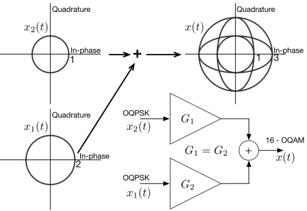
2.3.7 Decomposition ofM2-OQAMinto severalOQPSKcomponents
To apply highly nonlinear power amplification directly to these schemes, it is necessary to ensure that the complex envelope,x(t), has the minimum amount of envelope fluctuations possible. Clearly, all multi-level constellations fromsubsection 2.3.5and2.9have high
2.4. SUPPORT PULSES
envelope fluctuations due to the different values ofaInandaQn. Nevertheless, it is possible to
decomposex(t)intoG=log2(M)different components with constant or quasi-constant
envelope, depending on the adopted pulse shape.
To decomposex(t), lets consider the constellation symbols for hierarchic constellations, since they include all the previous modulations explained. Merging (2.11), (2.12) and (2.13) it is possible to re-writex(t)as
x(t) = G
∑
g=1xg(t), (2.14)
where
xg(t) = ϕ(g) N−1
∑
n=−Ncpg
∏
m=1bnI(m)r(t−nTs) + g
∏
m=1bQ(m)n r(t−nTs−To)
!
. (2.15)
Now, every xg(t)component can be regarded as an OQPSK signal, which in fact has
constant or quasi-constant envelope, allowing highly nonlinear amplification.
The main problem with this scheme is thatGbalanced power amplifiers are needed (Fig.2.9) to produce the initially desired modulation.
+
Quadrature
In-phase
1
3
Quadrature
In-phase
1
Quadrature
In-phase
2
+
16 - OQAM
OQPSK OQPSK
x
1(t)
x
2(t)
x(t)
G
1G
2x
1(t)
x
2(t)
x(t)
G
1=
G
2Figure 2.9: Decomposition ofM2-OQAMfor highly nonlinear amplification.
2.4
Support Pulses
CHAPTER 2. LITERATURE REVIEW
ISIthat results from the communication channel, while simultaneously optimizing the spectrum of the transmitted signal.
Nyquist defined a strategy to limit the spectrum of a signal avoiding at the same time ISI [CC09]. Let us consider
y(t) =
∑
nanp(t−nTs) (2.16)
as the received waveform. To guarantee zero ISI,p(t)needs to have the following property
p(t) =
(
1 t=0 0 t=±nTs
, n6=0. (2.17)
Under this condition, the only symbol different than zero at the decision timet=nTs, will
bean, which means null inter symbol interference.
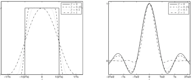
2.4.1 Raised Cosine Pulses
One common pulse shape in digital modulation is the raised cosine pulse. This class of pulse shapes is characterized by a roll-off factor, usually denoted byβ. In the frequency domain its mathematical description is
P(f) =
Ts , f ≤ 12−Tβs
Ts 2
n
1+coshπTs
β
|f| −12−Tβs io , 12−Tsβ ≤ f ≤ 12+Tβ
s
0 , f ≥ 12+Tβ
s
. (2.18)
In time domain we may write
p(t) =sinc
t Ts
cosπβt Ts
1−4βT22t2 s
. (2.19)
Figure 2.10illustrates these kind of pulses, for different roll-of factors. When a raised cosine pulse withβ=1 is applied, it is possible to reach a quasi-constant envelope fluctuation [GM76]. However, even in this case, there are still slight envelope fluctuations.
2.4.2 Minimum Shift Keying Pulses (half sinusoid)
The minimum shift keying modulation is a continuous phase modulation that can be regarded as a subtype ofOQPSKmodulation. InMSKsignals, the adopted pulse shape is a half sinusoid, resulting in a constant envelope signal. This support pulse1is defined as
r(t) =cos
πt
2Ts
rect
t
2Ts
, (2.20)
and has the following frequency spectrum
R(f) =Tssinc
2Ts
f − 1
4Ts
+Tssinc
2Ts
f+ 1
4Ts
. (2.21)
1r(t)is the pulse shape before the matched filter andp(t)is the pulse shape after the matched filter.
2.4. SUPPORT PULSES
−1/(2Ts) 0 1/(2Ts) 1/Ts
−1/Ts 0 Ts
f −
Ts/2
−Ts 0 Ts/2 Ts 3Ts/2
−3Ts/2 0 1
t
β= 0
β= 0.25
β= 0.5
β= 1
β= 0
β= 0.25
β= 0.5
β= 1
Figure 2.10: Raised cosine with different roll-off factors. Frequency spectrum (left) and time domain pulse (right).
As mentioned before, a constant envelope signal has great robustness to nonlinear amplifi-cation distortion. In fact, it can be shown that bandpass memoryless nonlinear devices do not distort constant envelope signals [GM76]. InFigure 2.11it is possible to see the time and frequency behavior of this modulation. Compared to raised cosines pulses, this modulation has much higher bandwidth occupation, but its envelope is constant.
−6/Ts −4/Ts −2/Ts 0 2/Ts 4/Ts 6/Ts 0
f
−Ts −Ts/2 0 Ts/2 Ts
0 1
t
CHAPTER 2. LITERATURE REVIEW
2.5
Envelope Fluctuations and Dynamic Range
For very-low-costMTit is desirable to have grossly nonlinear power amplifiers, which are simpler to implement, have higher amplification efficiency and output power. However, these amplifiers are only recommendable if the signal at its input has an almost constant envelope, otherwise it will distort the transmitted signal.
CPMschemes [Aul+81] are constant-envelope modulations that includeMSKand GMSK, among others. These modulations can be denoted asOQPSK-type modulations since they can be decomposed as the sum ofOQPSKcomponents [Ga+97;Lau86].OQPSK -type modulations also include other "non-CPM" schemes with constant or almost constant envelope and good trade-offs between spectral and power efficiencies [Mon06]. The OQPSKformat can even be employed to define Trellis Coded Modulation (TCM) schemes with good code gains [MG99].OQPSK-type schemes are particularly important in the context of a nonlinear amplification since anOQPSK-type signal retains itsOQPSK-type structure when submitted to bandpass memoryless nonlinear devices (that agree with the usual model for power amplifiers [Sal81]) which simplifies the performance evaluation and receiver design [DGa95]. The major problem with OQPSK signals with very low envelope fluctuations is that their bandwidth is much higher than the symbol rate.
−1 1
−1 1
QPSK
I
Q
−1 1
−1 1
OQPSK
I
Q
−1 1
−1 1
I
Q
−1 1
−1 1
I
Q
` = 0
` = 1
Figure 2.12: IQ Diagrams for QPSK and OQPSK signals with raised cosine support pulses with different roll off factors.
2.6. BLOCK TRANSMISSION TECHNIQUES
−3 −1 1 3
−3
−1 1 3
16−QAM
I
Q
−3 −1 1 3
−3
−1 1 3
16−OQAM
I
Q
−3 −1 1 3
−3
−1 1 3
I
Q
−3 −1 1 3
−3
−1 1 3
I
Q
` = 1
` = 0
Figure 2.13: IQ Diagrams for 16-QAM and 16-OQAM signals with raised cosine support pulses with different roll off factors.
On the other hand, to avoid ACI, a high separation between frequency channels is required, which reduces the overall spectral efficiency. A promising technique was proposed in [Din+05] forQPSKsignals where the separation between frequency channels is equal to the symbol rate, regardless of the transmission bandwidth associated to each channel. To cope with the high interference levels associated to the overlap between adjacent channels, an iterative frequency-domain receiver with joint equalization and ACIsuppression was proposed in [Din+05]. That receiver can be regarded as a frequency-domain iterative equalizer [BT02a;Ga+07] that takes advantage of spectral correlations for the separation of cyclostationary signals in overlapping bands. Unfortunately, the receiver of [Din+05] has poor performance forOQPSKschemes due to the inherentIQIof offset modulations [Luz+09]. Moreover, conventional synchronization and channel estimation techniques [Din+08;SS00] are not appropriate in scenarios with strongACI.
2.6
Block Transmission Techniques
CHAPTER 2. LITERATURE REVIEW
performance and complexity ofSCMcombined withFDEis similar toOFDM. However, since the Peak-to-Average Power Ratio (PAPR) is much lower than that of theOFDM schemes, it allows less peak power backoff on power amplification and is less susceptible to frequency offsets [Fal+02]. Therefore,SC-FDEschemes are particularly interesting for the uplink transmission (from the MT to theBS). Moreover, to reduce costs, increase coverage and autonomy, theMTshould only have moderate complexity, achieve efficient low-cost power amplification and all the complex signal processing operations should be kept at theBS.
The transmitter and receiver structures in both approaches are very similar. The main difference is that the Inverse Fast Fourier Transform (IFFT) block onOFDMis present on the transmitter, whether inSC-FDE, it appears on the receiver (Figure 2.14). This makes a crucial difference between both methods: inOFDMthere are several narrow subcarriers in parallel, with each one of them carrying one data stream. In SCMdata streams are carried over one single carrier, in a serial fashion. Therefore the equalization and channel estimation techniques inOFDMare less complex, since the channel response over each single subcarrier is assumed to be flat, making possible to equalize every subcarrier by a simple gain and phase factor. Nevertheless, the robustness to radio frequency hardware impairments, specially for low cost and power consumption wirelessMTturnsSC-FDE an attractive alternative toOFDM[Ben+10].
Figure 2.14:SC-FDEandOFDMinteroperability [Fal+02].
Nowadays,SC-FDEis not trying to replaceOFDM, but rather complement it. In fact, SC-FDEcan morph to a special form of multicarrier transmission that can be called Discrete Fourier Transform (DFT)-precoded OFDM. In the European 6th framework program, the Wireless INitiative NEw Radio (WINNER) project proposedDFT-precodedOFDM for its uplink transmission andOFDMfor the downlink [IST06]. The Third Generation Partnership Project - Long Term Evolution (3GPP-LTE) and now LTE-Advanced standards group also propose Single Carrier with Frequency Division Multiple Access (SC-FDMA) for the uplink of next-generation wide area cellular broadband wireless systems, which
2.6. BLOCK TRANSMISSION TECHNIQUES
is formally equivalent toDFT-precodedOFDM, withOFDMfor the downlink channel [Myu+06]. Furthermore, the WiMAX metropolitan area concept, that followed the early 802.16a standard has two transmission modes based onOFDMand one based onSCM. In fact, when coded and iterative or turbo equalization is employed, the performance of SCMimproves even further, exceeding that ofOFDMfor both ideal channel knowledge and for iterative channel estimation [Lam+07]. Nevertheless, the differences are not large and always depend on the employed system’s equalization, coding, multiuser detection, channel estimation and coding techniques [Ben+10].
This thesis will focus on uplink transmission and, therefore, its main focus will be on SC-FDEschemes. Nevertheless the work in this thesis is easily extended toDFT-precoded OFDMorSC-FDMAsystems.
2.6.1 Single Carrier with Frequency Domain Equalization
A linear single carrier modulation is a modulation where the energy associated to each symbol spreads along the total transmission band. The complex envelope of aNsymbol burst can be described as
x(t) = N−1
∑
n=0anr(t−nTs), (2.22)
wherer(t)represents the transmitted pulse,Tsis the symbol duration andanis a complex
coefficient representing thenth data symbol mapped in the selected signal constellation (e.g., PSKorQAMconstellation). Applying theDFTto (2.22) we obtain the frequency domain description of the complex envelope given by
X(f) =DFTnx(t)o= N−1
∑
k=0AkR(f)e−j2πf kTs, (2.23)
whereR(f)represents the Fourier Transform (FT) ofr(t)and AktheFTofan. Therefore,
the transmission band, associated with each data symbol, is the same as the band occupied byR(f).
ForISI-free transmission at the receiver’s matched filter bound, the pulse r(t)shall verify the orthogonality condition
Z ∞
−∞r(t−nTs)r
∗ t−n′T
sdt=0,n6=n′. (2.24)
In conventional SC modulations, offering bit rates of Mbits/s over severely time-dispersive channels is hard to achieve, since the transmission bandwidth becomes much greater than the transmission channel’s coherence bandwidth. This leads to high distortion levels which require complex receiver equalization.
CHAPTER 2. LITERATURE REVIEW
to modulations with low envelope fluctuations, which relaxes power amplification re-quirements. This kind of block-wise transmission has been called single carrier frequency domain equalization.
SC-FDE schemes require a Cyclic Prefix (CP) before every transmitted block. This prefix, shown inFigure 2.15, is a repetition of the lastNcpdata symbols in a block and is
needed to prevent block contamination byISIfrom the previous block. Another purpose is to make the received block appear to be cyclic with a period ofNTs.
CP
Cyclic
Prefix N data symbols block
Figure 2.15: Cyclic Prefix.
To ensure that the Inter Block Interference (IBI), from the previous block, is non-existent, the length of theCPshall be greater than the channel impulse response. This means that the first data symbol only hasISIfrom theCPsymbols, and since these can be estimated, it is possible to remove its interference from the following symbols. The complex envelope of aNsymbol burst, including theCP, is similar to one of a normalSC(2.22),
x(t) = N−1
∑
n=−Ncpanr(t−nTs), (2.25)
but hasNcpmore symbols to remove theIBI. The negatively indexedanvalues are given
bya−n =aN−n. Therefore, at the transmitter node (Figure 2.16and2.17) will be necessary
to do the following simple procedures:
• add theCP,
• modulate the data symbols in the desired modulation,
• and multiply the remaining block with the transmitted impulser(t).
On the other hand, the signal processing at the receiver, forcesSC-FDEto have the same order of complexity of anOFDMscheme, and its set of actions depends on the type of equalization employed [Cim85].
2.7
Equalization Methods
Equalization techniques try to minimize the channel effects inflicted on the transmitted signal. This process depends on the modulation used in the transmission technique. Therefore, only the relevant modulation scenarios will be discussed.