Bruno Miguel Domingues da Cunha
Licenciado em Ciˆencias da Engenharia Electrot´ecnica e de Computadores
High Performance Faster-than-Nyquist
Signaling
Disserta¸c˜ao apresentada para obten¸c˜ao do Grau de Mestre em Engenharia Electrot´ecnica e de Computadores, pela Universidade Nova de Lisboa,
Faculdade de Ciˆencias e Tecnologia.
Orientadores: Rui Dinis, Professor Associado com Agrega¸c˜ao, FCT-UNL Lu´ıs Bernardo, Professor Auxiliar com Agrega¸c˜ao, FCT-UNL
J´uri:
Presidente: Prof. Doutor Paulo Montezuma Arguente: Prof. Doutor Francisco Cercas
Vogal: Prof. Doutor Rui Dinis
High Performance Faster-than-Nyquist Signaling
Copyright © Bruno Miguel Domingues da Cunha, Faculdade de Ciˆencias e Tecnologia, Universidade Nova de Lisboa
Acknowledgments
I owe my deepest thanks and acknowledgements to so many people that, in different ways, helped me over the course of writing my dissertation, motivated and guided me into the right path or just made me look the right way with perseverance and a smile on my face. For all of you that made this possible my most sincere and heartfelt thank you.
First and foremost I offer my sincerest gratitude to both my advisors, Prof. Dr. Rui Dinis and Prof. Dr. Luis Bernardo, for welcoming me so warmly as their student. Thank you for all the help in the development and the writing of this thesis. Their constant and unconditional guidance, patience and knowledge are some of the most valuable assets that I will carry with me for the future.
I would like to acknowledge Prof. Rui Dinis for introducing me to the exciting world of wireless communication. It is an honor to have met such a brilliant and yet so approachable and down to earth person. I will always recall him every time I hear the word ”teacher”.
I will always remember the precious help and all the support given by Prof. Luis Bernardo who, in the most difficult moments, has motivated and guided me on this academic journey. His expertise in communication networks, combined with a selfless attitude, made him such a valuable asset on this work. His genuine support will be always valued.
To someone who is more than a colleague and whose availability was crucial
ii
throughout this dissertation, Francisco Ganh˜ao, who is one of the most helpful and supportive people I have come across in my life. A rare and kind human being that will always have my sincere gratitude and friendship. A special word to Ros´ario Caldeira, whose unconditional help enriched even more this document.
It is said that college times are the best years of our lives and I totally agree. To all of those who made my university experience unique and striking, who helped me in difficult times and shared the good ones a big thank you. To everyone in the Electrical Engineering Department’s Telecommunications office for their help in the most stressful moments. A special word for the whole AEFCT football team, for all the happy moments shared. You are like family to me!
To all my loyal and most dear friends who helped all the way through college, their support and advice since the very first moments have made all the difference. The way that all of them touched my life is so unique and diverse that I could not have done without any of them. Their support since the beginning of my thesis was my most powerful weapon. Thank you Andr´e Ricardo, Lu´ıs Ramos, Fl´avio Silva, Jo˜ao Marques, Andr´e Ramos, Tom´as Henriques, Bernardo Fontes, Ant´onio Magalh˜aes, Fernando Franco, Pedro Moiteiro, Diogo Freire, Tiago Estˆev˜ao, Pedro Granada, Jo˜ao Santos, Carolina Damas and more recently Guilherme Rosa, Jos´e Coelho, Pedro Brites, Jos´e Soares, Nuno Barreira and Andr´e Arrimar.
Last, but definitely not least, a big and special thank you to the most important part of my life: my family. I am deeply indebted to my parents, Francisco and Irene, for their never-ending support and believing in me. Thank you also to my sister Ana for everything she has taught me over the years. To my beloved grandparents Rosa and Ad˜ao, the strongest couple alive, and Cˆandida and Manuel, two truly inspiring people. Finally, to my beloved Margarida, for being always present and for blindly believing in my capacity even when I doubted myself.
Resumo
Num sistema de telecomunica¸c˜oes m´oveis, os canais de propaga¸c˜ao multi-percurso dispersivos no tempo afectam consideravelmente a liga¸c˜ao ascendente da comunica¸c˜ao de dados do terminal m´ovel (MT). ´E normalmente proposta a t´ecnica SC-FDE (Single Carrier with Frequency Domain Equalization) para lidar com canais altamente dispersivos no tempo para este tipo de comunica¸c˜ao. No entanto, os sistemas actuais baseiam-se no teorema de Nyquist e assumem que um sistema de comunica¸c˜oes m´oveis necessita de uma banda de frequˆencias no m´ınimo de 2W por MT. Por outro lado, a t´ecnica Faster-than-Nyquist (FTN) assume que ´e poss´ıvel utilizar uma banda de at´e 0.802 da banda de Nyquist original com perdas m´ınimas - apesar disto, a literatura corrente apenas conseguiu propor receptores demasiado complexos para uma caracteriza¸c˜ao simples do canal de comunica¸c˜ao sem fios. Al´em disso, a liga¸c˜ao ascendente entre o MT e a BS do SC-FDE pode ser afectada de forma intensa devido a desvanecimentos profundos ou pobres condi¸c˜oes de canal; para lidar com este problema, utiliza-se a t´ecnica Diversity Combining (DC) Hybrid ARQ (H-ARQ) que combina m´ultiplas c´opias do pacote enviado pelo MT a fim de criar um pacote confi´avel no receptor.
Nesta disserta¸c˜ao consideramos o uso de sinaliza¸c˜ao FTN para a liga¸c˜ao ascendente num sistema de comunica¸c˜oes m´oveis com igualiza¸c˜ao SC-FDE e um receptor baseado em IB-DFE (Iterative Block with Decision Feedback Equalization), aliado a um esquema de acesso ao meio agendado com H-ARQ (Hybrid Automatic Repeat reQuest), especialmente desenvolvido tendo em conta as caracter´ısticas do sinal
iv
FTN. Esta abordagem alcan¸ca melhores resultados que a sinaliza¸c˜ao de Nyquist ao aproveitar a largura de banda adicional oferecida pelo pulso root-raised cosine pulse para diversidade.
Juntamente com um modelo anal´ıtico do PER (Packet Error Rate), os resultados das simula¸c˜oes efectuadas demonstram que o receptor apresenta um melhor desempenho quando comparado com um sistema normal, com melhorias ao n´ıvel do d´ebito do sistema e energia gasta por pacote (EPUP).
Abstract
In a wireless broadband context, multi-path dispersive channels can severely affect data communication of Mobile Terminals (MTs) uplink. Single Carrier with Frequency-Domain Equalization (SC-FDE) has been proposed to deal with highly dispersive channels for the uplink of broadband wireless systems. However, current systems rely on older assumptions of the Nyquist theorem and assume that a system needs a minimum bandwidth 2W per MT. Faster-Than-Nyquist (FTN) assumes that it is possible to employ a bandwidth as low as 0.802 of the original Nyquist bandwidth with minimum loss - despite this, the current literature has only proposed complex receivers for a simple characterization of the wireless channel. Furthermore, the uplink of SC-FDE can be severely affected by a deep-fade and or poor channel conditions; to cope with such difficulties Diversity Combining (DC) Hybrid ARQ (H-ARQ) is a viable technique, since it combines the several packet copies sent by a MT to create reliable packet symbols at the receiver.
In this thesis we consider the use of FTN signaling for the uplink of broadband wireless systems employing SC-FDE based on the Iterative Block with Decision Feedback Equalization (IB-DFE) receiver with a simple scheduled access Hybrid Automatic Repeat reQuest (H-ARQ) specially designed taking into account the characteristics of FTN signals. This approach achieves a better performance than Nyquist signaling by taking advantage of the additional bandwidth employed of a root-raised cosine pulse for additional diversity.
Alongside a Packet Error Rate (PER) analytical model, simulation results show that
vi
this receiver presents a better performance when compared with a regular system, with higher system throughputs and a lower Energy per Useful Packet (EPUP).
Acronyms
3GPP 3rd Generation Partnership Project
ARQ Automatic Repeat reQuest AWGN Additive White Gaussian Noise BER Bit Error Rate
BPSK Binary Phase Shift Keying BS Base Station
CC Code Combining
CDMA Code Division Multiple Access CIR Channel Impulsive Response CP Cyclic Prefix
DAMA Demand Assigned Multiple Access DC Diversity Combining
DFE Decision Feedback Equalization DFT Discrete Fourier Transform DS-CDMA Direct-Sequence CDMA EPUP Energy Per Useful Packet FDE Frequency Domain Equalization FDMA Frequency Division Multiple Access FEC Forward Error Correction
FFT Fast Fourier Transform
FTN-SA Faster-Than-Nyquist Scheduled Access FTN Faster-Than-Nyquist
viii
H-ARQ Hybrid Automatic Repeat reQuest HSDPA High-Speed Downlink Packet Access HSUPA High-Speed Uplink Packet Access
IB-DFE Iterative Block Decision Feedback Equalization IDFT Inverse Discrete Fourier Transform
IEEE Institute of Electrical and Electronics Engineering IFFT Inverse Fast Fourier Transform
ISI InterSymbol Interference LTE Long Term Evolution
M-QAM Multi-level Quadrature Amplitude Modulation MAC Medium Access Control
MFB Matched Filter Bound
MMSE Minimum Mean Square Error MSE Minimum Square Error MT Mobile Terminal
OFDM Orthogonal Frequency Division Multiplexing PAPR Peak-to-Average Power Ratio
PER Packet Error Rate
PMEPR Peak-to-Mean Envelope Power Ratio PSD Power Spectral Density
PSK Phase Shift Keying
QAM Quadrature Amplitude Modulation QoS Quality of Service
QPSK Quadrature Phase Shift Keying SA Scheduled Access
SC-FDE Single Carrier with Frequency Domain Equalization SC Single Carrier
ix
SNR Signal-to-Noise Ratio
TDMA Time Division Multiple Access
Contents
Acknowledgments i
Resumo iii
Abstract v
Acronyms vii
1 Introduction 1
1.1 Motivation . . . 1
1.2 Outline . . . 3
1.3 Major Contributions . . . 5
2 Transmission Techniques 7 2.1 Phase Modulation Methods . . . 8
2.1.1 Generality . . . 8
2.1.2 Binary Phase Shift Keying . . . 9
2.1.3 Quaternary Phase Shift Keying . . . 10
2.2 Support Pulses . . . 12
2.2.1 Ideal Nyquist Channel . . . 13
2.2.2 Raised Cosine Pulses . . . 14
2.2.3 Root-Raised Cosine Pulses . . . 15
2.3 Faster-than-Nyquist Signaling . . . 17
2.4 Single Carrier with Frequency Domain Equalization . . . 18
2.4.1 Linear Frequency Equalization . . . 21
2.5 Iterative Block with Decision Feedback Equalization . . . 23
2.5.1 Definition . . . 25
2.5.2 Receiver Parameters . . . 25
2.5.3 IB-DFE with Soft Decisions . . . 27
2.5.4 Conclusions . . . 28
xii CONTENTS
2.6 Medium Access Control . . . 29
2.6.1 Time Division Multiple Access . . . 30
2.6.2 Frequency Division Multiple Access . . . 31
2.6.3 Demand Assigned Multiple Access . . . 32
2.7 Error Correction Schemes . . . 32
2.7.1 Forward Error Correction . . . 33
2.7.2 Automatic Repeat Request . . . 34
2.7.3 Diversity Techniques . . . 34
2.7.4 Hybrid-ARQ schemes . . . 35
2.8 Chapter Overview . . . 38
3 Iterative FDE for Faster-than-Nyquist Signaling 41 3.1 Motivation . . . 42
3.2 System Characterization . . . 44
3.2.1 Bandwidth Diversity . . . 46
3.3 IB-DFE Receiver Analysis . . . 47
3.4 Performance Results . . . 51
3.5 Conclusions . . . 56
4 H-ARQ Time Division Multiple Access Model 57 4.1 System Characterization . . . 58
4.2 Analytical Model . . . 58
4.2.1 Reception Probabilities . . . 59
4.2.2 Throughput . . . 60
4.2.3 Energy Comsumption . . . 60
4.2.4 Throughput Gain . . . 61
4.3 Model Performance . . . 62
4.4 Conclusions . . . 67
5 Scheduled Access H-ARQ for Faster-than-Nyquist Signaling 69 5.1 System Description . . . 70
5.1.1 Bandwidth Diversity . . . 73
5.2 Analytical Performance Model . . . 74
5.2.1 MAC Reception Probabilities . . . 75
5.2.2 Packet’s Mean Service Time . . . 76
5.2.3 Throughput . . . 76
5.2.4 Energy Comsumption . . . 77
CONTENTS xiii
5.3 Performance Results . . . 80 5.4 Conclusions . . . 84
6 Conclusions 87
6.1 Final Considerations . . . 87 6.2 Future Work . . . 89
Appendix 91
List of Figures
2.1 BPSK signal constellation. . . 10 2.2 BPSK signal binary message (a) and transmitted waveform (b). . . . 10 2.3 QPSK signal constellation. . . 11 2.4 Ideal Nyquist waveforms. Frequency spectrum (a) and time domain
pulse (b). . . 14 2.5 Raised Cosine pulses in frequency domain (a) and time domain (b). . 15 2.6 Root-Raised Cosine pulses in the frequency domain (a) and time
domain (b). . . 16 2.7 Root-raised cosine in the frequency domain for a roll-off α = 0.5 for
Nyquist and FTN signaling. . . 18 2.8 Data burst with Cyclic Prefix. . . 20 2.9 Basic SC-FDE transmitter. . . 20 2.10 Tx block in a SC-FDE transmitter. . . 21 2.11 Basic SC-FDE receiver. . . 21 2.12 Rx block in a SC-FDE receiver. . . 22 2.13 SC-FDE equalization structure. . . 22 2.14 IB-DFE receiver block diagram without (a) and with an L-branch
space diversity (b). . . 24 2.15 BER in a AWGN channel assuming different iterations of the IB-DFE
receiver. . . 29 2.16 TDMA . . . 31 2.17 FDMA . . . 31
3.1 Raised cosine pulse in the frequency domain for different roll-off values. 43 3.2 BER of Ideal Nyquist signaling (α = 0), square-root raised-cosine
pulse (α = 0.5) and FTN signaling (β = 0.802) in a AWGN channel assuming linear equalization. . . 44 3.3 Root-raised cosine, P†(f), in the frequency domain for a roll-offα =
0.5 for Nyquist and FTN signaling. . . 45
xvi LIST OF FIGURES
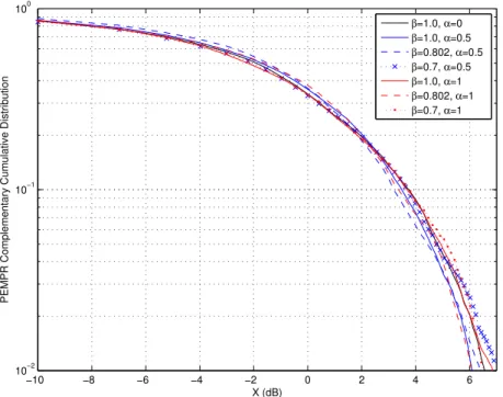
3.4 Complementary comulative distribution of the PMEPR for FTN (β =
{0.7; 0.802}) and Nyquist signaling(β = 1) for α={0; 0.5; 1}. . . 53 3.5 BER of FTN (β = {0.7; 0.802}) and Nyquist signaling (β = 1) for
α={0; 0.2; 0.5; 1} in a AWGN channel assuming linear equalization. . 53 3.6 BER of FTN (β = {0.7; 0.802}) and Nyquist signaling (β = 1) for
α= 0.5 in a multi-path dispersive channel for up toNiter = 4 iterations. 54
3.7 BER of FTN (β ={0.7; 0.802}) and Nyquist signaling (β = 1) forα = 0.5 in a multi-path dispersive channel with and without bandwidth diversity for Niter = 4 iterations. . . 55
3.8 BER of FTN (β = {0.7; 0.802}) and Nyquist signaling (β = 1) for α = {0; 0.2; 0.5; 1} in a multi-path dispersive channel with diversity for Niter= 4 iterations. . . 56
4.1 Bandwidth efficiency for FTN signaling in a TDMA system. . . 59 4.2 PER for β = 1 with α = 0.5 and L = {1; 2; 4} up to Niter = 4
iterations without bandwidth diversity (K = 1). . . 63 4.3 PER for β = {0.7; 0.802; 1} with α = 0.5 and L = {1; 4} up to 4
iterations without bandwidth diversity (K = 1). . . 64 4.4 PER for β = 1 with α = 0.5 and L = {1; 2; 4} up to 4 iterations
with(out) bandwidth diversity (K ={1; 2}). . . 65 4.5 PER for β = {0.7; 0.802; 1} with α = 0.5 and L = {1; 4} and 4
iterations with(out) bandwidth diversity (K ={1; 2}). . . 66 4.6 Saturated throughput for β = {0.7; 0.802; 1} with α = 0.5 and L =
{1; 2; 4} and 4 iterations with(out) bandwidth diversity (K ={1; 2}). 66 4.7 EPUP for FTN (β = {0.7; 0.802}) and Nyquist signaling (β = 1),
both with with α = 0.5 and L = {1; 2; 4} for 4 iterations with(out) bandwidth diversity (K ={1; 2}). . . 67
5.1 Slot duration for long and short blocks, in comparison with TDMA. . 71 5.2 Data block and respective side replicas, for a roll-off of α = 0.5 for
Nyquist and FTN signaling. . . 72 5.3 Packet Error Rate (PER) of H-ARQ FTN (β = 0.802) and Nyquist
signaling (β = 1) for α= 0.5 and Niter = 4 iterations. . . 81
5.4 Packet Error Rate (PER) of H-ARQ FTN (β = 0.7) and Nyquist signaling (β = 1) for α= 0.5 and Niter = 4 iterations. . . 82
LIST OF FIGURES xvii
5.6 Saturated system throughput forβ ={0.7; 0.802; 1}withα= 0.5 and L={1; 2; 4}for Niter = 4 iterations. . . 83
List of Tables
2.1 Phase values for different symbols in QPSK. . . 11
4.1 Simulation parameters. . . 62
5.1 Simulation parameters. . . 81
List of Symbols
Ac Carrier Amplitude
an nth symbol in a burst
Be Number of bits per symbol
B(ki) Feedback coefficients of the IB-DFE
E[N] (β) Expected service time for a TDMA with FTN factorβ
EN(1)
Service time of the long FTN block
EN(2)
Service time of the short FTN block
E[τ] Mean service time for SA-FTN
d Distance in meters
Eb Average bit energy
Ep Packet transmission energy
fc Carrier frequency
Fk Feed-forward component in a linear receiver
Fk(l,i) Feed-forward coefficients of the IB-DFE
GF T N Throughput gain of FTN signaling
xxii LIST OF SYMBOLS
G1 Gain factor at a distance of d= 1 m
Hk Channel frequency response
i ith iteration of the receiver
j Slot time of the FTN block
J Number of members in a group of MTs
l l-th packet transmission
L Maximum number of transmissions
K Redundancy used for bandwidth diversity
M Number of bits in a data packet
Ml Link margin gain
N Number of symbols in a data block
N0 Power spectral density of the noise
Ncp Cyclic prefix length
Niter Number of iterations of the IB-DFE
Nk Channel noise for the k-th frequency
P(f) Signal frequency response
P†(f) Signal replicas of a data block
p(t) Signal time response
LIST OF SYMBOLS xxiii
Rs Signal bit rate
Ssat(β) Saturated throughput for a FTN factorβ
T1 Large slot time for SA-FTN with H-ARQ
T2 Short slot time for SA-FTN with H-ARQ
Ts Signal period
W Signal Bandwidth
xI(t) In-phase signal component
xQ(t) Quadrature signal component
Yk Frequency domain data samples
α Raised cosine pulse roll-off factor
β Faster-than-Nyquist reduction factor
βT Ratio of the transmission power over the amplifier’s power
γ(i) Residual ISI component
ǫ(pl) Packet error rate for a l-th transmission
κ Characteristic power-path loss
ξ Inverted SNR
ρ(i) Correlation coefficient
σ2
N Total variance of the channel noise
xxiv LIST OF SYMBOLS
Φ(x) Gaussian error function
φc Carrier phase
Chapter 1
Introduction
1.1
Motivation
The design of future broadband wireless systems presents considerable challenges since those systems are expected to have high power and spectral efficiencies over communication channels that, due to multipath signal propagation between the transmitter and the receiver, are subjected to strong time-dispersive effects [1], [2]. However, it is known that high power and spectral efficiencies are confliting goals since the increase in one is achieved at the decrease of the other.
It is well known that the minimum bandwidth for a bandlimited transmission without Inter-Symbol Interference (ISI), also known as Nyquist bandwidth, is half the symbol rate. This is possible to achieve by employing sinc pulses that satisfy the Nyquist criterion. Since symbol-spaced pulses are orthogonal, a relatively simple receiver based on a matched filter can present optimum performance, identical to the one achieved when an isolated pulse is transmitted. To overcome the implementation difficulties inherent to the use of a sinc pulse (i.e. filter with ideal rectangular shape), most communication systems employ the so-called raised-cosine pulses (actually square-root raised-cosine pulses are employed in this dissertation; after a matched filter raised-cosine pulses are obtained), wich are simple to implement, although
2 CHAPTER 1. INTRODUCTION
occupy a slightly higher bandwidth (tipically with a roll-off factor above 0.25) wich reduces the system’s spectral efficiency. This extra bandwidth is generally regarded as an unavoidable price to pay when designing communication systems in general and wireless communication systems in particular, wich are known to have significant power and bandwidth constraints.
A much less known fact is that it is possible to achieve optimum asymptotic performance with a bandwidth below the minimum Nyquist band. In fact, by employing the so-called Faster-than-Nyquist (FTN) signaling the transmission band can be reduced to around 80% without compromising the minimum Euclidean distance between differente binary sequences, in spite of the inherent ISI levels [3]. This remarkable result was almost completely ignored for over 30 years mainly because the optimum receiver with FTN signaling was too complex. However, due to spectrum scarcity and advances in signal processing there is a renewed interest in FTN (see [4] and references within). Faster-than-Nyquist signaling is particularly interesting for broadband wireless systems. However, the scenario is even more complex if we consider that the ISI inherent to FTN signaling is combined with the ISI associated to multipath time-dispersive effects, which leads to much higher ISI levels that cannot be handled by conventional FTN receivers (even the simplified receivers from [5], [6] are too complex). Block transmission techniques combined with Frequency-Domain Equalization (FDE) such as Orthogonal Frequency Division Multiplexing (OFDM) [2] and Single-Carrier with FDE (SC-FDE) [7] are widely recognized as the best candidates for the downlink and uplink, respectively [8], [9]. Although a linear FDE is suitable for OFDM, it is far from optimum for SC-FDE. In that case, the most promising FDE is the so-called nonlinear IB-DFE (Iterative Block Decision-Feedback Equalizer) [10].
1.2. OUTLINE 3
those copies might present errors as well, since channel conditions might not vary for subsequent retransmissions leading to a throughput degradation. Fortunately, the use of Hybrid Automatic Repeat reQuest (H-ARQ) [11] can be useful in such conditions, specially when employing Diversity Combining (DC) H-ARQ [1], since it uses the individual copies from each symbol, received at the BS, to create a packet with better reliability with appropriate equalization techniques.
To take the full advantages of FTN signaling, a scheduled access H-ARQ architecture can be considered with two different data block sizes. After a failed transmission of a FTN slot with β size, the remaining symbol replicas can be retransmitted in a slot with size 1−β, allowing the receiver to combine them and achieve a Nyquist signaling equivalent performance. Such approach can achieve a bandwidth efficiency gain of up to 1/β.
It is important to note that the models developed in this thesis are general in terms of the technology in use, since one of the main objectives of this thesis is to achieve energy and bandwidth efficiency for wireless communications in general.
1.2
Outline
This document is structured in a total of six chapters as enumerated in the paragraphs below.
4 CHAPTER 1. INTRODUCTION
In chapter 3 it is considered the use of Faster-than-Nyquist (FTN) signaling for the uplink of wireless broadband systems employing SC-FDE schemes. An IB-DFE receiver is presented, specially designed to cope with the overall ISI inherent to both FTN signaling and multi-path time dispersive channels. Results on the Bit Error Rate (BER) are discussed for different values of the FTN factor β, as well as for increasing iterations and bandwidth diversity methods.
Chapter 4 presents an efficient H-ARQ technique using TDMA that takes into account the characteristics of the FTN with SC-FDE scheme and the IB-DFE receiver considered in chapter 3. The employment of Diversity Combining (DC) is considered, since it uses the individual copies from each symbol received to create a packet with better reliability. Also, given the shorter bandwidth of the FTN pulse, the bandwidth efficiency of the system is depicted through an analytical model for the PER and MAC performance.
In chapter 5 a different MAC approach is proposed, considering a scheduled access FTN with H-ARQ architecture which uses two different data block sizes depending on the FTN factor β. This allows, given a high success rate of the initial FTN transmission achieved by the IB-DFE receiver, a bandwidth efficiency and throughput gains of up to 1/β. An analytical model for the throughput and energy per useful packet (EPUP), as well as a simulation script are presented in order to validate the obtained results.
1.3. MAJOR CONTRIBUTIONS 5
1.3
Major Contributions
In result of the work developed in this thesis, the major contributions are enumerated below.1
A FTN signaling model for a SC-FDE context at the uplink, where the BS takes advantage of the full diversity from the root-raised cosine pulse using the IB-DFE technique for equalization is proposed in chapter 3. It presents similar results to an orthogonal pulse for a higher roll-off and a smaller bandwidth. The model and its results were submitted for the 2014 IEEE 80th Vehicular Technology Conference
(VTC2014-Fall).
A FTN PER model using the receiver proposed in chapter 3 and a DC H-ARQ architecture to enhance packet reception are presented. Analytical model and simulation results, depicted in chapter 4, were published in [12].
A Hybrid ARQ scheme combined with IB-DFE detection, both specially designed for FTN signaling, is proposed in chapter 5. A simple analytical model for this technique and its respective simulation results were submitted for the 2015 IEEE 81st Vehicular Technology Conference (VTC2015-Spring).
Chapter 2
Transmission Techniques
The main purpose of nowadays communication systems, in particular wireless systems, is to achieve low cost mobile terminals, hand to hand with higher data rates and high power and spectral efficiencies. To obtain it, non-linear power amplifiers are often used. In order to design constant envelope signals, able to cope with the high non-linear distortion of this type of amplification, we need to employ modulation schemes where information is transmitted in the signal phase, such as Phase Shift Keying (PSK). Therefore, this chapter will discuss PSK techniques, such as Binary-PSK (BBinary-PSK) and Quaternary-Binary-PSK (QBinary-PSK). To diminish the complexity of mobile terminals, the transmitter has to be as simple as possible, transferring all possible processes to the base station. This leads to the use of Single-Carrier (SC-FDE) schemes in the uplink, due to their efficiency against fading and ISI channels as well as implementation simplicity. In an higher level, the most efficient method of Medium Access and Error Control will be discussed, in order to organize admittance to the base station, as well as to detect and correct possible errors in transmitted data. Therefore, MAC techniques and error control schemes will be characterized, such as Hybrid-ARQ and diversity techniques, which plays an important role in the development of this dissertation.
The chapter is organized as follows: section 2.1 explains the basic principles behind
8 CHAPTER 2. TRANSMISSION TECHNIQUES
phase modulation methods, such as BPSK and QPSK schemes; section 2.2 shows a brief characterization of the support pulses used through this thesis; section 2.3 pays special attention to Faster-than-Nyquist signaling; section 2.4 gives an overall description of Single Carrier with Frequency Domain Equalization (SC-FDE); section 2.5 describes a non-linear frequency equalization method called Iterative Block Decision Feedback Equalization (IB-FDE), a deeply important tool regarding this dissertation; section 2.6 presents a brief description of medium access control schemes and, finally, section 2.7 focus on error correction schemes, specially the Hybrid-ARQ technique.
2.1
Phase Modulation Methods
In baseband data transmission, the entire sequence of input data is represented as a discrete wave modulated by pulse amplitude (PAM) that can be transmitted in a low pass channel. However, in wireless communications, due to constraints of the physical channel in use, the data stream is modulated onto a carrier, typically sinusoidal, limited in frequency by a predetermined band-pass channel as a micro-wave channel, a radio channel or a satellite channel. In any case, the modulation process involves switching (keying) the amplitude, frequency or phase of a sinusoidal carrier in accordance with the incoming data. In this section it is considered only phase modulation, more specifically Phase Shift Keying (PSK), a technique commonly used in most mobile communication applications.
2.1.1
Generality
2.1. PHASE MODULATION METHODS 9
frequency of this signal constant, while switching the phase according to the original data stream.
Consider the sinusoidal carrier
x(t) =Accos(2πfct+φc) (2.1)
where Ac is the carrier amplitude, fc the frequency and φc the carrier phase.
We may describe it in terms of its in-phase and quadrature component as
x(t) =Accos(φc)cos(2πfct)−Acsen(φc)sen(2πfct)
=Re
Ac ejφc(t)ej2πfct
=xI(t)cos(2πfct)−xQ(t)sen(2πfct). (2.2)
The components xI(t) andxQ(t) are low-pass signals. They are uniquely defined in
terms of the band-pass signal x(t) and the carrier frequency fc, provided that the
half-bandwidth of x(t) is less than the carrier frequency fc.
2.1.2
Binary Phase Shift Keying
The binary PSK contains phase shifts of ±π radians. This signal can be expressed as
x(t) =Accos(2πfct+φc) (2.3)
where the phase component φc assumes the values
φc(t) =
0 , for symbol 1
π , for symbol 0
10 CHAPTER 2. TRANSMISSION TECHNIQUES
The in-phase and quadrature component of this signal are
xI(t) =±Ac and xQ(t) = 0 (2.5)
and a BPSK signal constellation is shown in Fig. 2.1.
1 0
! !"
#
Figure 2.1: BPSK signal constellation.
The waveform of a BPSK signal is shown in Fig. 2.2.
!"
a)
b)
#
Figure 2.2: BPSK signal binary message (a) and transmitted waveform (b).
2.1.3
Quaternary Phase Shift Keying
The quaternary PSK can be expressed as a combination of two BPSK signals in quadrature. The carrier signal x(t) used,
x(t) =Accos(2πfct+φc) (2.6)
2.1. PHASE MODULATION METHODS 11
represent
φc(t) =
π
4 , for symbol 11 3π
4 , for symbol 01
−3π
4 , for symbol 00
−π
4 , for symbol 10
(2.7)
Therefore, the in-phase and quadrature component of this signal are
input dibit φc xI(t) xQ(t)
00 −3π
4 −A
√
2 2 −A
√
2 2
01 3π
4 −A
√ 2 2 A √ 2 2
10 −π
4 A
√
2
2 −A
√ 2 2 11 π 4 A √ 2 2 A √ 2 2
Table 2.1: Phase values for different symbols in QPSK.
A QPSK signal constellation is shown in Figure 2.3.
11 10 01 00 ! !" #
12 CHAPTER 2. TRANSMISSION TECHNIQUES
2.2
Support Pulses
One of the biggest challenges in wireless communication lies in controlling the inter symbol interference (ISI) resulting from a dispersive communication channel. The choice of a proper pulse shape that not only eliminates this aspect but also optimizes the spectrum of the transmitted signal is, therefore, crucial. Let us consider
s(t) =X
k
akr(t−kTs) (2.8)
where r(t) is the support pulse, as the modulated signal to transmit, and Ts is the
signal period. This signal is modified as a result of transmission (a convolution operation) through the channel of impulse response h(t)
x(t) = s(t) ⋆ h(t) = Z +∞
−∞
s(τ) h(t−τ) dτ (2.9)
and then passed through a receive filter, resulting on y(t) in the form of a modified PAM signal
y(t) =X
n
akp(t−kTs) (2.10)
being p(t) the received pulse1 to be defined, result of the convolution
p(t) = r(t) ⋆ h(t) (2.11)
To guarantee zero ISI, the following conditions should be respected, known as the
2.2. SUPPORT PULSES 13
”Nyquist criterion for distortionless baseband transmission”. [13]
p(t) = p(kTs) =
p(0) , k = 0
0 , k 6= 0
X
n
P(f− n Ts
) =Cte (2.12)
Under this property, the only symbol different from zero at the decision timet =kTs
will be ak, therefore eliminating the inter symbol interference.
2.2.1
Ideal Nyquist Channel
The simplest form of satisfying (2.12) is to shape the frequency function P(f) in form of a rectangular pulse, rect(f), characterized by
P(f) =
1
2W , −W < f < W
0 , |f|> W
(2.13)
with the overall bandwidth W defined by
W = Rs
2 =
1 2Ts
(2.14)
where W defines the bandwidth andRs the bit rate of the pulse. From the
Fourier-Transform, it is finally found that a signal waveform that respects the Nyquist criterion for zero ISI is defined by
p(t) = sen(2πW t) 2πW t
14 CHAPTER 2. TRANSMISSION TECHNIQUES
known as the sinc function. The bit rate value Rb = 2W is called the ”Nyquist
rate”and the bandwidth W the ”Nyquist bandwidth”. According to this, the signal produced by (2.13) in frequency domain and (2.15) in time domain, and illustrated in figure 2.4 is known as the ”ideal Nyquist pulse”.
−1/Ts −1/(2Ts) 0 1/(2Ts) 1/Ts
0 Ts
f
(a)
Ts −Ts/2 0 Ts/2 Ts
0 1
t
(b)
Figure 2.4: Ideal Nyquist waveforms. Frequency spectrum (a) and time domain pulse (b).
2.2.2
Raised Cosine Pulses
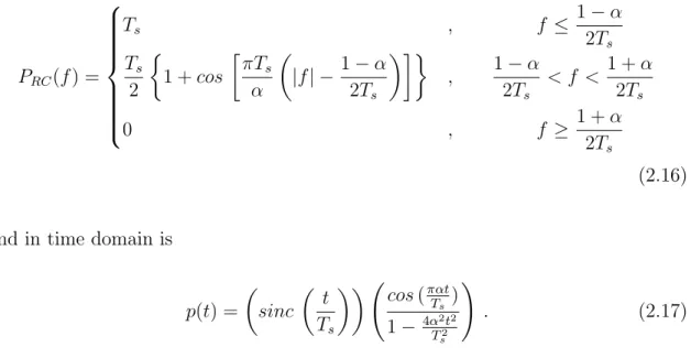
2.2. SUPPORT PULSES 15
mathematical equation in the frequency domain is
PRC(f) =
Ts , f ≤
1−α 2Ts
Ts
2
1 +cos
πTs
α
|f| −1−α 2Ts
, 1−α
2Ts
< f < 1 +α 2Ts
0 , f ≥ 1 +α
2Ts
(2.16)
and in time domain is
p(t) = sinc t Ts
cos(παt
Ts )
1− 4αT22t2
s
!
. (2.17)
Figure 2.5 illustrates these pulses, according to different roll-off factors.
0 1/(2Ts) 1/Ts
0 Ts
f
α = 0 α = 0.25 α = 0.5 α = 0.75 α = 1
(a)
Ts −Ts/2 0 Ts/2 Ts
0 1
t
α = 0 α = 0.25 α = 0.5 α = 0.75 α = 1
(b)
Figure 2.5: Raised Cosine pulses in frequency domain (a) and time domain (b).
2.2.3
Root-Raised Cosine Pulses
16 CHAPTER 2. TRANSMISSION TECHNIQUES
section 2.2.2. Its mathematical expression could be written as
PRRC(f) =
p
|PRC(f)| (2.18)
Therefore, the Raised Cosine pulse shape can be expressed as the multiplication of two Root-Raised Cosine pulses:
PRC(f) = PRRC(f)·PRRC(f) (2.19)
As it is possible to observe in Figure 2.6, which illustrates these pulses according to differentroll-off factors, and unlike the Raised Cosine filter, the Root-Raised Cosine impulse response is not zero at the intervals of ±Ts. Only in the case of α = 0 the
Root-Raised Cosine has zeros at ±Ts.
0 1/(2Ts) 1/Ts
0 Ts
f
α = 0 α = 0.25 α = 0.5 α = 0.75 α = 1
(a)
Ts −Ts/2 0 Ts/2 Ts
0 1
t
α = 0 α = 0.25 α = 0.5 α = 0.75 α = 1
(b)
2.3. FASTER-THAN-NYQUIST SIGNALING 17
2.3
Faster-than-Nyquist Signaling
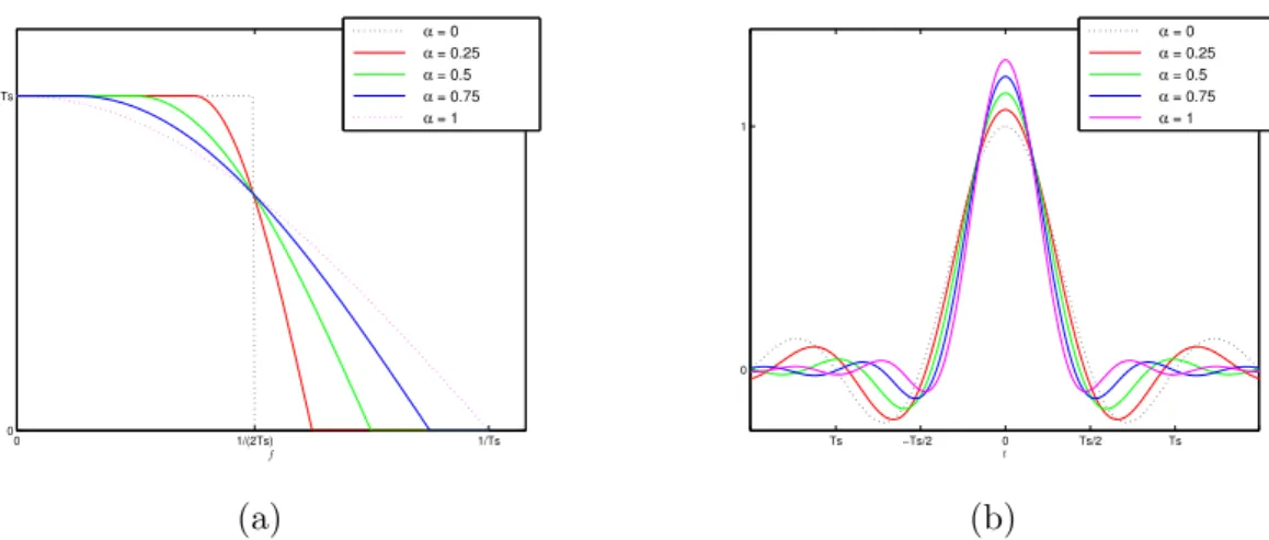
As seen before, a band-limited transmission without inter symbol interference (ISI) is possible to achieve by employing pulses that satisfy the Nyquist criterion, with the most popular being the so-called Raised Cosine pulses (and Root-Raised Cosine pulses as well), with a minimum bandwidth of half the symbol rate, also known as Nyquist bandwidth. The maximum spectral efficiency is associated to the minimum bandwidth, that increases with the roll-off factor α, usually required to be above 0.25, due to implementation difficulties. This extra bandwidth is generally regarded as unavoidable when designing wireless communication systems, however, it is still possible to achieve optimum asymptotic performance with a bandwidth below the minimum Nyquist bandwidth, through applying Faster-than-Nyquist signaling. In fact, for binary signaling we can reduce the symbol separation by a factor β up to 0.802 without asymptotic performance degradation, which is usually known as ”Mazo’s limit”[3]. This FTN factor, where β ≤ 1, corresponds to the Nyquist bandwidth occupation W of the Faster-than-Nyquist pulse
βW = (1−∆f)W . (2.20)
18 CHAPTER 2. TRANSMISSION TECHNIQUES
Fc−W0 Fc−W/2 Fc Fc+W/2 Fc+W
1
f
Nyquist pulse, α = 0.5 FTN pulse, α = 0.5, β = 0.802 FTN pulse, α = 0.5, β = 0.7 Square pulse
Figure 2.7: Root-raised cosine in the frequency domain for a roll-off α = 0.5 for Nyquist and FTN signaling.
2.4
Single
Carrier
with
Frequency
Domain
Equalization
2.4. SINGLE CARRIER WITH FREQUENCY DOMAIN EQUALIZATION 19
from a direct mapping of the original data into a selected signal constellation. For a linear modulation, the complex envelope of an N-symbol burst can be written as
s(t) =
N−1
X
n=0
anr(t−nTs) (2.21)
wherean is a complex coefficient that corresponds to thenth symbol, mapped in the
selected signal constellation (e.g., PSK (Phase Shift Keying) or QAM (Quadrature Amplitude Modulation) constellation), r(t) represents the support pulse and Ts
refers to the symbol duration. By applying the Fourier Transform (FT) to (2.21) we obtain
S(f) =F{s(t)}=
N−1
X
k=0
AkR(f)e−j2πf kTs (2.22)
where R(f) denotes the FT of the support pulse r(t) and Ak the Discrete Fourier
Transform (DFT) of an. Therefore, the transmission bandwidth associated with
each data symbol is equal to the band occupied byR(f). For a transmission without ISI at the receiver’s matched filter bound, the r(t) pulse must verify the following orthogonality condition
Z +∞
−∞
r(t−nTs) r∗(t−n′Ts) dt= 0, n6=n′. (2.23)
If conventional SC modulations are employed requiring data transmission rates of Mbits/s over severely time-dispersive channels high signal distortion levels can arise, which will increase the complexity of the receiver equalization required to overcome this problem, as the transmission bandwidth becomes much greater than the channel’s coherence bandwidth.
20 CHAPTER 2. TRANSMISSION TECHNIQUES
block and it is also useful to make the received block appear to be cyclic with period N Ts. To ensure that the inter-block interference (IBI), from the previous block, is
absent, the length of the CP should be longer than the channel impulse response.
CP
!"#$%&'(#"&(')* +$)(,)"
-./0,1
Figure 2.8: Data burst with Cyclic Prefix.
The complex envelope of the transmitted signal, a N symbols burst with a CP appended, is now
s(t) =
N−1
X
n=−Ncp
anr(t−nTs) , (2.24)
where r(t) is the support pulse and Ts represents the symbol period. The
transmission structure of a SC-FDE scheme is described in Figure 2.9, where a cyclic prefix is attached to the N symbols burst
S/P converter
P/S converter
Add CP Tx
Data
N N+Ncp
Figure 2.9: Basic SC-FDE transmitter.
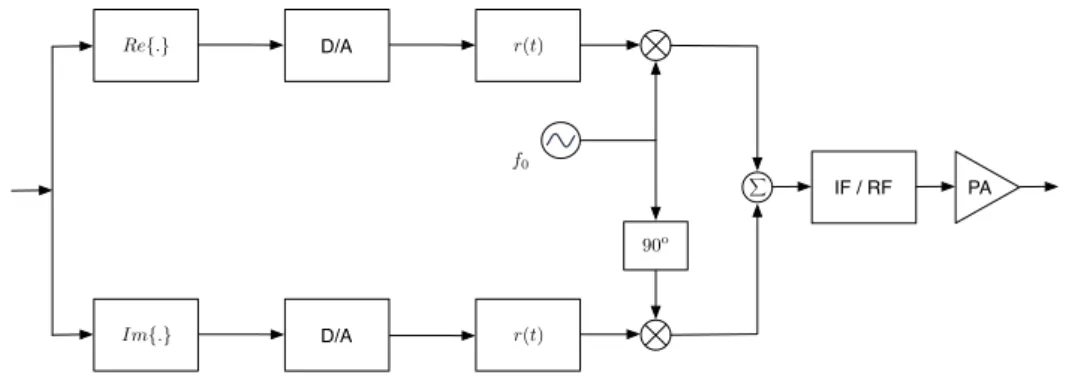
2.4. SINGLE CARRIER WITH FREQUENCY DOMAIN EQUALIZATION 21
Re{.} D/A
D/A
IF / RF PA
Im{.}
r(t)
r(t)
90o f0
X
Figure 2.10: Tx block in a SC-FDE transmitter.
2.4.1
Linear Frequency Equalization
The use of block-wise transmission using FDE at the receiver’s side is based on the DFT [8] [9], which can be efficiently implemented through the Fast Fourier Transform (FFT) algorithm. This approach reduces significantly the receiver’s complexity and, when combined with modulations with low envelope fluctuations, can achieve reduced Peak-to-Mean Envelope Power Ratio (PMEPR) leading to low power amplification requirements.
S/H A/D S/P
Rx
Remove-CP
N+Ncp N
{yn}
y(t)
Figure 2.11: Basic SC-FDE receiver.
At the reception structure, represented in the diagram of Fig. 2.11 and 2.12, the received signal is demodulated, being down-converted and filtered, sampled and A/D converted The resulting signal is then converted to parallel and the CP samples are removed resulting on the N initial data symbols, leading in the time-domain the samples {yn;n= 0, ..., N −1}.
frequency-22 CHAPTER 2. TRANSMISSION TECHNIQUES
Figure 2.12: Rx block in a SC-FDE receiver.
domain samples {Yk;k = 0, ..., N −1}, with Yk given by
Yk =HkAk+Nk (2.25)
where Hk and Nk represents the channel frequency response and noise term in
frequency-domain for the kth frequency, respectively.
IFFT
Decision+Device
FFT
{yn} {Yk}
{Fk}
{A˜k} {˜an} {ˆan}
Figure 2.13: SC-FDE equalization structure.
After equalization and for a linear FDE, the estimated frequency-domain samples ˜
Ak are given by
˜
Ak=FkYk (2.26)
where {Fk;k = 0, ..., N − 1} represents a different coefficient value to each kth
2.5. ITERATIVE BLOCK WITH DECISION FEEDBACK EQUALIZATION 23
denoted by
Fk=
1 Hk
= Hk∗
|Hk|2
, (2.27)
or by employing a Minimum Mean Square Error (MMSE) criterion, avoiding the previous stated problem and minimizing the combined effect of ISI and channel noise, which leads to the set of optimized coefficients
Fk=
H∗ k
ξ+|Hk|2
(2.28)
with ξ as the inverted signal-to-noise ratio (SNR). The equalized samples {A˜k;k =
0, ..., N −1} are then converted back to the time-domain by a IFFT block leading to the time-domain equalized samples {˜an;n= 0, ..., N −1}, which will be used to
make decisions on the transmitted symbols.
2.5
Iterative
Block
with
Decision
Feedback
Equalization
24 CHAPTER 2. TRANSMISSION TECHNIQUES
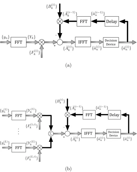
in [17] and extended to diversity scenarios in [16]. These schemes implement both feedforward and feedback equalization in the frequency domain in an iterative way.
IFFT Decision+Device
FFT
FFT Delay
+ _ {yn}
{Bk(i)}
{Fk(i)} {
˜
A(ki)} {˜a(i)
n } {ˆa(ni)}
{aˆ(i−1)
n }
{Aˆ(ki−1)}
{Yk}
(a)
IFFT Decision+Device
FFT
FFT Delay
+ _ {Bk(i)}
{A˜(ki)} {˜a(i)
n} {ˆa(ni)} {ˆa(i−1)
n } {Aˆ(ki−1)}
FFT {y(1)
n } {Y
(1) k }
{Fk(1,i)}
{Fk(L,i)} {y(L)
n } {Y
(L) k }
X
(b)
Figure 2.14: IB-DFE receiver block diagram without (a) and with anL-branch space diversity (b).
From Figure 2.14, it can be seen that for the first iteration, as there is no information regarding an, the IB-DFE reduces to a linear FDE. For the next iterations, the
2.5. ITERATIVE BLOCK WITH DECISION FEEDBACK EQUALIZATION 25
feedforward coefficients perform an approximate matched filtering. Thus, it becomes clear that IB-DFE techniques offer a much better performance than non-iterative methods.
2.5.1
Definition
Let us consider anL-order space diversity IB-DFE for SC-FDE scheme. For a given ith iteration, the ˜A(i)
k frequency output samples are defined as
˜ A(ki)=
L
X
l=1
Fk(l,i)Y l k −B
(i)
k Aˆ
(i−1)
k , (2.29)
where {Fk(l,i) ; k = 0,1, ..., N −1; l = 1, ..., L} and {Bk(i) ; k = 0,1, ..., N −1} represents the feedforward and feedback equalizer coefficients, respectively,{Yl
k ; k=
0,1, ..., N − 1} is the DFT of the time-domain received block and {Aˆ(ki) ; k =
0,1, ..., N − 1} is the DFT of the hard-decision block of the (i − 1)th iteration
associated to the transmitted data block.
2.5.2
Receiver Parameters
The feedforward and feedback IB-DFE coefficients Fk(i) and Bk(i), respectively, are chosen in order to maximize the ”Signal-to-Interference plus Noise Ratio”(SINR). Considering an IB-DFE with ”hard-decisions”, the optimum feedforward coefficients are given by
Fk(l,i) = κ
(i)H(l)∗ k
ξ+h1−(ρ(i−1))2iPL
l′=1|H
(l′) k |2
26 CHAPTER 2. TRANSMISSION TECHNIQUES
and the feedback coefficients are
Bk(i) =ρ(i−1)
L
X
l′=1
Fk(l′,i)Hk(l′)−1 !
(2.31)
where κ(i) is selected to ensure that γ(i) = 1, ξ as the inverted signal-to-noise ratio
(SNR) and the correlation coefficientρ(i), a measure of the reliability of the decisions
used in the feedback loop, is defined as
ρ(i) =
Ehˆa(ni)a∗n
i
Eh|an|2
i =
EhAˆ(ki)A∗ k
i
Eh|Ak|2
i . (2.32)
The residual ISI component, γ(i), in the frequency domain, associated to the
difference between the average channel frequency response after the feedforward filter, is defined as
γ(i) = 1
N
N−1
X
k=0
L
X
l′=1
Fk(l′,i)Hk(l′) , (2.33)
which would have a constant value for null ISI. Clearly, γ(i) can be regarded as the
average overall channel frequency response at the ith iteration, after combining the
outputs of the L output filters.
It is important to remark that, for the first iteration (i = 0), the information about an is unavailable, which means that ρ = 0 and Bk(0) = 0. Under these conditions,
the values of Fk(0) are easily obtained by
Fk(l,0) = κ
(0)H(l)∗
k
ξ+PL
l′=1|H
(l′) k |2
, l = 1,2, ..., L (2.34)
2.5. ITERATIVE BLOCK WITH DECISION FEEDBACK EQUALIZATION 27
are derived from the equations above assuming L = 1.
2.5.3
IB-DFE with Soft Decisions
To improve the IB-DFE performance, increasing immunity against error propagation, it is possible to use ”soft-decisions” by replacing the ”blockwise averages” by ”symbol averages”, which can be done in the following way.
For a normalized QPSK constellation under a Gray mapping rule , i.e. aI
n =
Re{an}=±1 and anQ =Im{an}=±1, following [17] and [18] we may write
¯ aI(i)
n =tanh
LIn(i)
2 !
(2.35)
and
¯ aQ(i)
n =tanh
LQn(i)
2 !
, (2.36)
where LI
n and LQn are the LLRs (Log Likelihood Ratios) of aIn and aQn, the in-phase
and quadrature bit estimation, respectively, given by
LIn=
2Re{˜a(ni)}
σ2
N
(2.37)
and
LQn =
2Im{˜a(ni)}
σ2
N
, (2.38)
with the total variance of the channel and interference noise, σ2
N, given by
σ2N = 1
2E[|an−a˜
(i)
n |
2
] ≈ 1
2N
N−1
X
n=0
|ˆa(i)
n −a˜
(i)
n |
2
28 CHAPTER 2. TRANSMISSION TECHNIQUES
In this case, the feedforward coefficients, Fk(i), are given by (2.30) and, since ¯A(ki) is equivalent to ρ(i)Aˆ(i)
k , the feedforward coefficients, B
(i)
k , are given by
Bk(i) =Fk(i)Hk−1. (2.40)
Finally, the estimated data symbols are obtained by
˜ A(ki) =
L
X
l=1
Fk(l,i)Yl k−B
(i)
k A¯
(i−1)
k . (2.41)
2.5.4
Conclusions
Clearly, the IB-DFE techniques offer much better performances than non-iterative methods [19]. With a conventional IB-DFE receiver the log-likehood values are computed on a symbol-by-symbol basis (i.e. it is not necessary to perform the channel decoding in the feedback loop). Consequently, conventional IB-DFE schemes can be considered as low complexity turbo equalizers [20] [21] since the feedback loop employs the equalizer outputs rather than the channel decoder outputs.
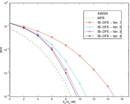
In Figure 2.15 it is shown the average BER performance for a fading channel. It is considered a SC modulation with a QPSK constellation, that uses a IB-DFE receiver with 1, 2, 3 and 4 iterations, as well as, for sake of comparison, the corresponding performances of the MFB and AWGN channel.
As it can be observed from the results, the Eb/N0 required for BER = 10−4, in
2.6. MEDIUM ACCESS CONTROL 29
0 2 4 6 8 10 12 14 16
10−4 10−3 10−2 10−1 100
Eb/N0 (dB)
BER
AWGN MFB
IB−DFE − Iter. 1 IB−DFE − Iter. 2 IB−DFE − Iter. 3 IB−DFE − Iter. 4
Figure 2.15: BER in a AWGN channel assuming different iterations of the IB-DFE receiver.
2.6
Medium Access Control
In telecommunications, Medium Access Control (MAC) schemes are important in a wireless environment to coordinate Mobile Terminals (MTs) eligible for packet transmission. This means that MAC protocols have the purpose to control the access of communicating stations to the wireless medium, sharing the network bandwidth [22]. Meanwhile, multiple MTs might contend the wireless channel and interfere with each other [23]. Therefore, the design of the access scheme is of extreme importance, since it should enhance the throughput of the system and diminish the interference between the different MTs. An analogy to this problem can be a room filled with people, all of them trying to talk with each other. If all of them talk at the same time, the message would not arrive correctly at the receptor due to the high level of noise.
30 CHAPTER 2. TRANSMISSION TECHNIQUES
medium are presented. The first one to be presented is the Time Division Multiple Access (TDMA) that allocates to each user a pre-defined time slot. Then, the Frequency Division Multiple Access (FDMA) which determines a different bandwidth to each MT and, at last, the Demand Assigned Multiple Access (DAMA) method is presented, as a way of increasing efficiency through an advanced capacity of slot reservation.
More recently, in order to support higher data rates and to be able to cope with severe multi-path propagation, two additional solutions were adopted in the WiMax/3GPP-LTE systems: Orthogonal Frequency Division Multiplexing (OFDM) and Single-Carrier Frequency Domain Equalization (SC-FDE), being the last one of the basis to this dissertation, as already mentioned before.
2.6.1
Time Division Multiple Access
TDMA consists in the pre-allocation of a different time-slot for each user terminal. The communication of MTs is made in carriers with the same frequency and bandwidth, with the limitation of only being possible to one device at the same time. For this to be feasible, it is mandatory the previous scheduling of MTs in time-slots, so that the terminal can exactly know the time interval when it is allowed to communicate. A prefix is introduced to each burst in order to synchronize the time-slots and correspondent messages. This information is extremely relevant because of the problem of the terminal spacial mobility and subsequent ”Round-Trip Time”variation.
2.6. MEDIUM ACCESS CONTROL 31
F
re
q
u
e
n
cy
Time
1 2 3 4 5
Figure 2.16: TDMA
2.6.2
Frequency Division Multiple Access
The FDMA channel access method is based on the Frequency Division Multiplexing (FDM) scheme, which associates different frequency bandwidth to each MT, that own full exclusivity of that band for its data stream. [22]
This technique was used in several communication systems before but, due to its limitations for a large bandwidth in ISI channels and receiver complexity, FDMA was improved by two additional approaches - OFDM and SC-FDE - used in Long Term Evolution (LTE) systems. An illustration of a FDMA scheme is shown in Fig. 2.17, where the assignment of individual frequencies for different users with no time restrictions can be observed.
F
re
q
u
e
n
cy
Time 1 2 3 4 5
32 CHAPTER 2. TRANSMISSION TECHNIQUES
2.6.3
Demand Assigned Multiple Access
DAMA is a class of multiple-access methods, intended to increase efficiency even more by an advance capacity reservation procedure. DAMA protocols allocate bandwidth to MTs according to their QoS constraints [24], based in FDMA or TDMA architectures, being suitable to situations where the traffic pattern is random and with large variations. Because of its ability to allocate capacity on demand, this protocol avoids an inefficient use of transponder capacity. MAC protocols that apply DAMA can use bandwidth efficiently and increase the throughput, due to the ability to allocate capacity on demand, following the station capacity requests. This reservation on demand can be explicit or implicit [25]. Regarding implicit reservation, stations compete for reservation slots by using Slotted Aloha. Slotted Aloha is a way to allocate users, by taking into account consensus among users on slot boundaries definition. By using slotted-Aloha protocol, the channel is slotted into segments with a duration exactly equal to single packet transmission time. Slotted-Aloha eliminates the partial overlapping, because terminals are synchronized to start the transmission of packets at the beginning of a slot. In Explicit Reservation, all frames have a control subframe with a sequence of bits, which serve to announce or reserve upcoming transmissions. This type of reservation scheme reserves future channel time, in order to send messages to a specific station.
2.7
Error Correction Schemes
2.7. ERROR CORRECTION SCHEMES 33
be employed. In this section, Forward Error Correction (FEC), Automatic Repeat Request (ARQ) and Diversity Techniques are discussed. As an important part of this dissertation, Hybrid-ARQ will be then discussed in detail.
2.7.1
Forward Error Correction
FEC schemes, also referred as error-correction codes, is a detection technique and posterior correction of ocasional errors in a data packet. The strategy used in FEC consists in the inclusion of additional redundant information in the data blocks to transmit, allowing the receiver to analyze and detect possible errors in order to confirm the correct reception of the package, or, if not, to correct the deficient data.
The FEC concept arrived during the 1940s, through the studies of R. W. Hamming, which proposed the famous Hamming codes at Bell laboratories, in order to prevent read errors in punch cards for rely-based electro-mechanical computers. In the following decades, new codes were born and, consequently, algorithms were created to handle these codes. During the evolution of FEC codes three generations can be identified. The first generation of FEC codes used linear block codes - it is based on hard decision coding, which consists in a single quantization level in a bit sampling. The second generation of FEC are concatenated codes which are, as the name suggests, a junction of more than one type of coding. At last, a special form of concatenated codes are Turbo Codes and Low Density Parity Check (LDPC), based on soft decisions and iterative decoding. [27]
34 CHAPTER 2. TRANSMISSION TECHNIQUES
2.7.2
Automatic Repeat Request
In an Automatic Repeat Request (ARQ) system the receiver, through an error-detecting code with a certain retransmission protocol, discards an erroneously received data packet if an error is detected and requests to the transmitter, using control messages, a retransmission of the data. This process is repeated as many times as necessary until the data packet is successfully received.
The error detection is possible due to the introduction of redundant bits in the data burst (like the FEC method mentioned before), which will be tested by the receiver. In case of correspondence with the expected data, the receiver informs the transmitter side of the success in the operation. Otherwise, an error is detected and the data is discarded, being requested the correspondent retransmission to the sender.
The main advantages of ARQ schemes lie in the low complexity and high reliability offered. Nevertheless, as data error rates increases, the system throughput substantially reduces due to the need of more redundant bits in the data packet as well as the number of retransmission requests increases.
2.7.3
Diversity Techniques
2.7. ERROR CORRECTION SCHEMES 35
Time diversity consists on the transmission of multiple versions of the same signal at different time instants [29]. Usually, it works by the BS demanding data retransmissions from a MT when the message is received with data errors. Automatic Repeat Request (ARQ) and Hybrid-ARQ schemes can be considered as a subset of the time diversity class, which will be explored in the following section. In frequency diversity the signal is transmitted using multiple frequency channels or spread over a defined bandwidth. This method, widely used in nowadays wireless communication systems as SC equalization (section 2.4), spread spectrum methods (CDMA) or Multi-Carrier systems like OFDM, presents the problem of non-linear frequency response, essentially due to the occurrence of fading and ISI in the communication channel. The methods presented before exploit and minimize these limitations through an efficient equalization with good results, being chosen for the LTE/WiMax 3GPP standards.
Finally, in spatial diversity the signal is transmitted through different propagation paths. This means, particularly in wireless communication, that the transmitter or the receiver terminals (in some cases both of them) use multiple antennas dealing with the signal. A well known example of spatial diversity is the Multiple Input Multiple Output (MIMO) scheme, a standard for LTE and 3GPP WiMax, where both the transmitter and the receiver use multiple antennas to improve communication performance. The different copies of the message are then combined in order to improve communication performance. [30]
2.7.4
Hybrid-ARQ schemes
36 CHAPTER 2. TRANSMISSION TECHNIQUES
the system throughput may be increased as these errors are corrected and, with this combination done in a proper way, the disadvantages of both techniques can be overcome [31]. This approach opens the door to a more reliable system than a FEC only and also a higher throughput system than ARQ only.
The H-ARQ schemes can be divided into two categories: Type-I Hybrid ARQ and Type-II Hybrid ARQ [31]. Hybrid ARQ techniques are currently used in 3GPPs High-Speed Downlink Packet Access (HSDPA), High-Speed Uplink Packet Access (HSUPA) and LTE. Furthermore, since the work done in this thesis relies on Hybrid-ARQ architectures, an overview will be given about this topic.
Type-I Hybrid-ARQ schemes
The Type-I Hybrid ARQ protocol is the simplest of hybrid protocols. In this technique, each data packet is encoded for error correction and error detection, suitable for both FEC and ARQ schemes. The message estimation and the error detection parity bits are output to an FEC decoder, which tests it for error detection to determine if the message should be accepted or rejected due to errors. It is possible to achieve better performance with this protocol when the message is long and/or the signal strength is low.
The crossover point in terms of performance between ARQ protocols and Type I H-ARQ protocols happens in cases where signal strength is high. In these cases, this hybrid protocol type does not improve the efficiency, because a strong signal allows the delivery of free error messages.
Type-II Hybrid-ARQ schemes
2.7. ERROR CORRECTION SCHEMES 37
extra parity-check bits are added to the codeword.
In this protocol, a message in its first transmission is coded with parity-check bits for error detection only, as in a pure ARQ scheme, forming a codeword. If the receiver detects an error in the respective codeword, it saves the erroneous word and requests a retransmission. Now, the retransmission is not necessarily the original codeword, as is in type-I scheme, but can be a block of parity-check bits formed based on the original codewords and an error-correcting code. After this block of parity-check bits has been received, it is used to correct the errors presented in the previous stored codeword. If it does not succeed, a second retransmission is requested. The second retransmission may be either a repetition of the first and original codeword or another block of parity-check bits, depending on the retransmission strategy and the type of error-correcting code to be used.
The main goal of Type-II H-ARQ protocols is to work with the efficiency given by plain ARQ protocols in strong signals and to obtain the improvement of type I H-ARQ when the quality of the signal is lower.
Code Combining and Diversity Combining
38 CHAPTER 2. TRANSMISSION TECHNIQUES
dissertation [32].
2.8
Chapter Overview
2.8. CHAPTER OVERVIEW 39
Chapter 3
Iterative FDE for
Faster-than-Nyquist Signaling
In the previous chapter was shown that block transmission techniques employing FDE equalization are suitable in a wireless broadband context, in order to handle multi-path dispersive channels. Typically, the receiver for SC-FDE schemes is a linear FDE. Being recognized that non-linear equalizers outperform linear equalizers [19], in this chapter it is presented an IB-DFE receiver specially designed to cope with the overall ISI inherent to both FTN signaling and severely time-dispersive multi-path channels. Bandwidth efficiency is here obtained by the use of FTN signaling for the uplink of broadband wireless systems, employing SC-FDE schemes and taking advantage of the additional bandwidth employed by the root-raised cosine pulse for additional diversity.
The work presented in this chapter was proposed for publication in the 2014 IEEE 80th Vehicular Technology Conference (VTC2014-Fall).
The chapter is organized as follows: Section 3.1 introduces the ISI problem when implementing FTN signaling with a root-raised cosine pulse shape; section 3.2 describes the pulse shape and the bandwidth diversity technique in use; in section 3.3 a detailed analysis on the IB-DFE receiver is presented; and in section 3.4
42 CHAPTER 3. IB-DFE FOR FASTER-THAN-NYQUIST SIGNALING
performance results on the BER are discussed.
3.1
Motivation
The minimum bandwidth for a ISI-free transmission, according to the assumption of the Nyquist theorem, is half the symbol rate: [13]
W = Rs
2 =
1 2Ts
. (3.1)
As discussed in section 2.2 raised cosine pulses (and root-raised cosine pulses) satisfy Nyquist’s criterion. A raised cosine pulse can be mathematically described as (subsection 2.2.3)
p(t) =
sinc
t Ts
cos(παt
Ts )
1−4αT22t2
s
!
(3.2)
in the time domain, and represented by (2.16) in the frequency domain. This solution is usually adopted in nowadays wireless communication systems as presents a much simpler practical implementation than the Nyquist’s ideal sinc pulse, that would require a filter with ideal rectangular shape. The inconvenience on this solution is that, although are simpler to implement, these pulses have a slightly higher bandwidth (typically with roll-off between 0.25 and 0.5). This bandwidth increase is regarded as an unavoidable price when designing wireless systems, known to have significant power and bandwidth constraints.
3.1. MOTIVATION 43
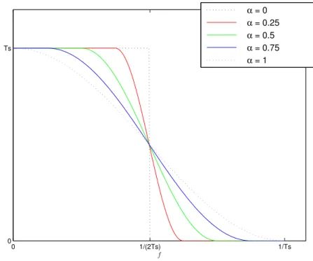
0 1/(2Ts) 1/Ts
0 Ts
f
α = 0
α = 0.25
α = 0.5
α = 0.75
α = 1
Figure 3.1: Raised cosine pulse in the frequency domain for different roll-off values.
the pulse for FTN occupies only
βW = (1−∆f)W (3.3)
44 CHAPTER 3. IB-DFE FOR FASTER-THAN-NYQUIST SIGNALING
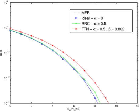
0 2 4 6 8 10 12
10−4 10−3 10−2 10−1 100
Eb/N0(dB)
BER
MFB
Ideal − α = 0
RRC − α = 0.5
FTN − α = 0.5 , β = 0.802
Figure 3.2: BER of Ideal Nyquist signaling (α= 0), square-root raised-cosine pulse (α = 0.5) and FTN signaling (β = 0.802) in a AWGN channel assuming linear equalization.
3.2
System Characterization
Let us assume a SC-FDE scheme with a IB-DFE receiver, using FTN signaling. A raised cosine pulse, for a roll-off factor α, symbol transmission time Ts (with
bandwidth W = 1/Ts) and a FTN factor β = (1− ∆f), where β ≤ 1, is often
characterized in the frequency domain as
R(f, β, α, Ts) =
Ts , 0≤ |f| ≤β12−Tsα
Ts
2
1 +cos
πTs
α
|f| −1−α 2Ts
, β1−α
2Ts ≤ |f| ≤β
1+α
2Ts
0 , |f|> β1+α
2Ts
3.2. SYSTEM CHARACTERIZATION 45
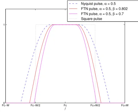
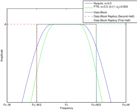
So, assuming a normalized root-raised cosine pulse for a carrier frequencyFc results
P†(f, Fc, β, α, Ts) =
s A2
Ts|
R(f−Fc, β, α, Ts)|. (3.5)
Figure 3.3 displays (3.5) with a roll-off α = 0.5 for a bandwidth W = 1/Ts, in the
frequency domain, for Nyquist and FTN signaling, where the pulse for FTN occupies only βW = (1−∆f)W = 0.802W of the Nyquist bandwidth. As observed in this
Fc−W Fc−W/2 Fc Fc+W/2 Fc+W
A
Frequency
Amplitude
Nyquist, α=0.5 FTN, α=0.5, β=(1−∆
f)=0.802
Data Block
Data Block Replica (Second Half) Data Block Replica (First Half)
Figure 3.3: Root-raised cosine, P†(f), in the frequency domain for a roll-offα= 0.5
for Nyquist and FTN signaling.