João Carlos Santágueda dos Santos Claro
Licenciado em Engenharia InformáticaTool for Spatial and Dynamic Representation
of Artistic Performances
Dissertação para obtenção do Grau de Mestre em Engenharia Informática
Orientadores :
Fernando Pedro Reino da Silva Birra,
Prof. Auxiliar, Universidade Nova de Lisboa
Nuno Manuel Robalo Correia,
Prof. Catedrático, Universidade Nova de Lisboa
Júri:
Presidente: Prof. Dra. Ana Maria Dinis Moreira
Arguente: Prof. Dr. João António Madeiras Pereira
iii
Tool for Spatial and Dynamic Representation of Artistic Performances
Copyright cJoão Carlos Santágueda dos Santos Claro, Faculdade de Ciências e Tecnolo-gia, Universidade Nova de Lisboa
Acknowledgements
As this document represents entering a new stage of my life, I would like to give out a few words of acknowledgment to show my gratitude.
First and foremost, I would like to thank my advisers, Fernando Birra and Nuno Cor-reia, for their trust in me and their support throughout this dissertation’s development.
Then, I would like to thank the Faculdade de Ciências e Tecnologia da Universidade Nova de Lisboa (FCT/UNL), for housing me for six years. I met great people here and had so many good times I will never forget, which helped me create much of the person I am today. I also have to thank the IT Department (DI) for providing me the much needed tools needed to develop this project.
I would also like to thank my colleagues for letting me experiment most of my work with them, helping me and laughing with me along the way.
I am forever grateful to my close friends, with whom many nights were spent after work, allowing me to relieve most of this stress inducing process called academic life. Thank you for sharing my life with you.
The most important thanks goes to my family, especially to my parents and brother. It is because of them I was able to get as far as I am today. I know many sacrifices were made, many hard times we went through together, but we proved we can do anything if we believe and never give up.
Abstract
This proposal aims to explore the use of available technologies for video representa-tion of sets and performers in order to serve as support for composirepresenta-tion processes and artistic performer rehearsals, while focusing in representing the performer’s body and its movements, and its relation with objects belonging to the three-dimensional space of their performances.
This project’s main goal is to design and develop a system that can spatially repre-sent the performer and its movements, by means of capturing processes and reconstruc-tion using a camera device, as well as enhance the three-dimensional space where the performance occurs by allowing interaction with virtual objects and by adding a video component, either for documentary purposes, or for live performances effects (for ex-ample, using video mapping video techniques in captured video or projection during a performance).
Resumo
Esta proposta visa explorar a utilização de tecnologias disponíveis para a represen-tação digital de cenários e autores das artes performativas de modo a servirem de apoio a processos de composição e ensaios, focando em especial na representação do corpo dos artistas e seus movimentos e na sua relação com objetos pertencentes ao espaço tri-dimensional das atuações.
A proposta visa o desenvolvimento dum sistema que permita representar espacial-mente o artista e os seus movimentos, por processos de captura e reconstrução, assim como aumentar o espaço tridimensional onde o artista atua permitindo-o interagir com objetos virtuais e adicionando uma componente vídeo, quer para efeitos documentais, quer para efeitos de atuações ao vivo (por exemplo, através da utilização de técnicas de
video mappingno vídeo capturado ou projeção durante uma atuação).
Contents
1 Introduction 1
1.1 Motivation . . . 1
1.2 Context . . . 2
1.3 Presented Solution . . . 2
1.4 Document Structure . . . 3
2 Related Work 5 2.1 Digital Tools for Artistic Performance Representation . . . 5
2.1.1 Virtual Reality Theatrical Performing . . . 5
2.1.2 Virtual Reality Dance Performing . . . 7
2.1.3 Virtual Avatar Automatic Rigging . . . 9
2.2 Motion Capture Cameras . . . 10
2.2.1 Microsoft Kinect . . . 10
2.2.2 Microsoft Kinect Version 2.0 . . . 13
2.3 Motion Capture and 3D Representation Assisting Tools . . . 14
2.3.1 Kinect Fusion . . . 14
2.3.2 Skanect . . . 17
2.3.3 Brekel Kinect . . . 17
2.3.4 NI Mate . . . 18
2.4 3D Simulation Engines . . . 19
2.4.1 Blender . . . 19
2.4.2 Unity . . . 21
2.5 Discussion . . . 22
3 System Model and Features 25 3.1 Data Acquisition and Representation . . . 25
3.1.1 Data Acquisition . . . 25
3.1.2 Data Representation . . . 28
xiv CONTENTS
3.2 Simulation Environment . . . 37
3.3 Discussion . . . 39
4 System Development 41 4.1 Architecture . . . 41
4.2 Data Input System . . . 42
4.3 Final Data Simulation . . . 44
4.4 Discussion . . . 48
5 Conclusions and Future Work 49 5.1 Evaluation . . . 49
5.2 Conclusion . . . 50
List of Figures
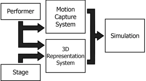
1.1 Diagram of the project’s initial architecture. . . 3
2.1 More elements are added to the virtual stage as a triggered response to the performer’s actions [4]. . . 6 2.2 A performer using a full body suit for capturing dance movements for the
virtual avatar to perform [8]. . . 8 2.3 Project RAM’s different visual effects created from the previous
move-ments done by the performer [10]. . . 8 2.4 Using a static character mesh and skeleton as input, a moving animation
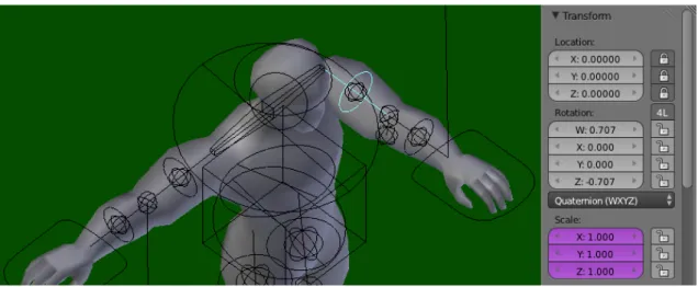
is automatically created [11]. . . 9 2.5 A rotation value was inserted in the selected node, rotating the model’s
arm. The node’s position (Location), however, is locked and cannot be modified. . . 10 2.6 An example of the Kinect basics: color stream data (a), depth stream data
(b), infrared stream data (c) and the corresponding skeleton tracking (d). . 12 2.7 Comparison between the images provided by the depth sensors of the
Kinect v1 (left) and the Kinect v2 (right) [24]. . . 14 2.8 An example of bilateral filtering application: a picture with no filtering (a)
and with bilateral filtering (b), smoothing the differences between pixels [18]. . . 16 2.9 The model starts being unrefined, but after continuous updates a state of
good definition is achieved [29]. . . 17 2.10 A reconstructed 3D mesh of a room using Skanect [33]. . . 18 2.11 Brekel’s main menu. We can observe the computed point cloud originated
from the depth and color images captured [38]. . . 19 2.12 One of the developers at Delicode using NI Mate to animate an existing rig
xvi LIST OF FIGURES
3.1 Kinect Common Bridge’s Skeleton example graphical display. . . 26
3.2 Kinect skeleton node positions and orientations [56]. . . 27
3.3 A tree representation of the Kinect v1.8 joints’ hierarchy. . . 28
3.4 Results of inanimate object reconstruction: the floor is captured along with chair (a), a small metal bar linking the handle and the main chair pillar is missing (b) and a final successful chair reconstruction (c). . . 29
3.5 Results of human body reconstruction: full scale body reconstruction in a casual pose (a) and T-pose attempt ends in a partial reconstruction of the arms due to the camera distance to the target (b). . . 30
3.6 Gimbal Lock example, two axes are pointing in exactly the same direction [57]. . . 31
3.7 MoCapPlay’s graphical environment. . . 33
3.8 Displaying a skeleton’s rest pose and its first frame of animation, taken from thejumpkick.bvhfile, in MoCapPlay. . . 33
3.9 Still frame shots of thejumpkick.bvhanimation file. . . 34
3.10 A tree representation of the Rigify created rig joints’ hierarchy. . . 35
3.11 The 3D model skeleton does not match the BVH skeleton because of the faulty chest node values. . . 35
3.12 Representation of armature bones with different orientations. . . 36
3.13 Prototype of the virtual performing stage created in Blender. . . 37
3.14 Using MoCapPlay to animate the 3D model to knock down the red box. . 38
3.15 Video being displayed on the wall in the back of the stage while the per-former dances. . . 39
4.1 Diagram of the project’s final prototype architecture. . . 42
4.2 Final armatures used for creating a rig with Rigify. . . 43
4.3 Final rigs created with their respective models and armatures. . . 43
4.4 Kinect Studio’s window display, after loading a file containing Kinect stream data. . . 47
List of Tables
3.1 Alignment quaternions used forjumpkick.bvhfile. All joint names are the Kinect’s equivalent joints, already referenced in figure 3.2(a). . . 37
Listings
3.1 Kinect SDK v1.8NUI_SKELETON_BONE_ORIENTATIONstructure . . . . 27 3.2 Kinect SDK v2JointOrientationstructure . . . 28 4.1 Code excerpt of the<nodes>group in the Kinect XML configuration file. . 46 4.2 Code excerpt of the<alignments>group in the Kinect XML configuration
1
Introduction
This dissertation addresses virtual representation of body movements and the surround-ing space in a performance over time in the context of ussurround-ing software for artistic re-hearsals purposes. This is a fairly recent concept, due to the rise of low cost motion capture cameras, and although there are already some experiments in this field it is cur-rently under-explored.
In this chapter, we further detail the main motivations and context surrounding this dissertation, pointing out the different options and limitations in this field, and present the overall layout of this document.
1.1
Motivation
The field of artistic performances has been evolving over time, incorporating digital sys-tems, making way for several applications to be created, either just to give a way for performers to study a routine or to give the viewers a richer experience with what is currently happening on stage.
1. INTRODUCTION 1.2. Context
1.2
Context
Moore’s Law1 states that in the course of time the number of transistors on integrated circuits doubles approximately every 18 months, meaning that powerful electronic de-vices will become smaller in size over time. This rapid increase in technology allows for the creation of several capture methods where, as an example, performers can attach various small motion capture devices to their limbs, capturing their performance with good precision, while still making the performer feel comfortable. As an alternative, by using motion sensor cameras it is also possible to capture these movements in a non in-trusive way, without the need to attach any peripherals to the performer, although the movements captured will probably be less accurate. The ability to record and analyze body movements can be very useful in several fields, such as artistic or theatrical perfor-mances, but can also be useful in other fields that require body movement analysis, such as sports.
By using 3D reconstruction methods, it is possible to recreate a stage where the per-formance can occur in virtual form. However, this process is not straightforward and requires complex algorithms and the use of very specific input devices, such as the Mi-crosoft Kinect, a low budget motion sensor camera [1].
Motion sensor devices can also be used for gesture recognition. This means that by performing specific gestures, performers can trigger certain events on a virtual stage, such as materialize objects, stretch them, make them appear or disappear, and several other visual effects. This allows for a different play on traditional performances, mixing both real world and virtual world by enabling real world human movements to influence what happens on a virtual stage.
By blending these concepts we can accurately capture the performers’ movements, the stage where they are performing and define their interactions with the stage elements.
1.3
Presented Solution
As mentioned before, there exists an inherent challenge in both capturing and depicting the routine movements in an accurate and precise way. Therefore, this project’s goal is to create a software tool that allows users to interact with a virtual stage using only a 3D virtual model, making use of a specific input device, such as the Microsoft Kinect, for motion sensor purposes. This software will serve as a support for composition processes or rehearsals, where the user can focus on specific body movements done by either a real or a virtual performer.
The tool is developed in C++ using the openFrameworks platform [2], a library ded-icated to creative graphical programming, specifically using the Kinect Common Bridge [3] add-on, which is a wrapper for the official Kinect Libraries. In order to accomplish the 3D graphical simulation our tool will communicate with Blender (section 2.4.1), a 3D
1http://www.mooreslaw.org/
1. INTRODUCTION 1.4. Document Structure
modeling software with an internal game engine, through add-ons developed in Python language.
Our initial system design is divided into two main systems, the motion capture sys-tem and the 3D representation syssys-tem, as represented in figure 1.1. The motion capture system focuses on capturing and interpreting the performer’s movements, being capable of detecting performers in front of a camera and represent their performance in some data format in real time. It also allows for playing recorded animation files instead, that follow the same movement data format. The 3D reconstructing system focuses on rep-resenting the performer’s body and the stage where the performance occurs in a virtual environment. The emulated 3D model is able to interact with any virtual objects in the virtual stage it is represented in. Video input is also used as part of the 3D represen-tation system. When combining the two systems, a simulation can happen, in which a previously created 3D model mimics the performer’s body movements, either detected through skeleton tracking in real time, or through animation files instead.
Figure 1.1: Diagram of the project’s initial architecture.
1.4
Document Structure
This document is divided into five main chapters - introduction, related work, concept and initial prototype, final prototype and conclusions and future work.
The first chapter,Introduction, presents an overview of the dissertation, addressing several issues such as the main motivation and context for this dissertation, and our presented solution.
The second chapter, Related Work, focuses on systems and tools similar to the pro-posed solution, where some of their features or techniques are relevant to the solution.
1. INTRODUCTION 1.4. Document Structure
each of the features is implemented. The initial steps of the development cycle are also defined in this chapter.
Then, in theSystem Developmentchapter, a final prototype is presented. All of the final intricacies regarding the development cycle are explained here.
Finally, theConclusions and Future Workchapter presents the overall conclusions regarding this project, combined with evaluation aspects, followed by the future work possibilities regarding our work.
2
Related Work
This chapter presents concepts and techniques used in the development of the proposed solution. In the following sections, several tools, techniques and systems relevant to the solution will be presented in detail. This chapter is composed of three sections. The first section addresses digital tools used for representing artistic performances. The sec-ond section is dedicated to tools used for motion capture and finally the third section discusses the several options available in 3D simulation software.
2.1
Digital Tools for Artistic Performance Representation
This section covers already existent digital tools with a similar context to our presented approach that are considered relevant to the solution.
2.1.1 Virtual Reality Theatrical Performing
Artists in the world of traditional theatrical performing have always been looking for new ways to entertain the viewers. One way to give viewers a new and refreshed experience is through virtual reality, and some of the ideas explored so far include creating a fully virtual performer avatar who acts by recognizing a performer’s actions, as seen in figure 2.1 [4], and even project holographic 3D stages [5], giving users a complete virtual theater experience.
2. RELATEDWORK 2.1. Digital Tools for Artistic Performance Representation
or even simulating things that would be too dangerous to do on a real stage like py-rotechnics.
However, this transition from the real world to a virtual one is not seamless, mostly because of its need for pre-programmed actions. If these actions are to be captured by non intrusive motion cameras, such as the Kinect, they depend on the environmental condi-tions where the accondi-tions are captured, taking the risk of the system not working properly. Virtual performers or avatars also usually follow a script, acting based on pre-recorded actions, not allowing them to be spontaneous and capable of any form of improvisation.
Using gesture recognition, it is possible to simulate improvisation, making a virtual avatar act based on what actions are performed by a real world performer, giving the illu-sion of responsiveness [4]. In order to make the human-avatar interaction seem as spon-taneous and human-like as possible, a large database of gestures and actions is needed. This requires an extensive list of avatar actions that need to be previously captured or pre-programmed, also requiring the performer to know every single gesture that makes the virtual avatar react, just to give the illusion that the avatar is acting on its own free will.
These approaches could also be combined into a mix between scripted sequences and inferred sequence. These last ones could be defined through machine learning by, for example, understanding the last movements executed by the performer and recognizing the sequence as a trigger for executing another action in stage. With this, any performer could define a sequence trigger, “teaching” it to the artificial intelligence system.
Figure 2.1: More elements are added to the virtual stage as a triggered response to the performer’s actions [4].
2. RELATEDWORK 2.1. Digital Tools for Artistic Performance Representation
2.1.2 Virtual Reality Dance Performing
As mentioned before in Chapter 1, some dances are based on routines, which define the performer’s procedural body movements over a period of time. Along with the introduc-tion of mointroduc-tion capture methods, new ways to perfect these routines started to appear. It became possible to record performances and perform a quick analysis of what move-ments were made, detecting and correcting all non intended movemove-ments.
This technique has previously been used to record dance routines for both solo prac-tice or group pracprac-tice. Bairdet al. presents an example of how routines can be recorded and reproduced in digital form [6]. They designed a tool that uses a library of small move-ments that follow Laban dance notation, where users select which movemove-ments from the library to perform and capture them wearing a motion capture suit [7]. The tool takes the recorded movements and places them in a 3D virtual environment, where the user is free to rearrange the order of the recorded movements to its liking, while getting feedback through a virtual avatar performing the sequence of movements selected.
Chanet al. created a system for performers to improve movements in an interactive way, consisting on using a virtual avatar that can teach and perform dance routines, mak-ing users match their movements [8]. These dance routines must be previously captured, and are performed by a professional dancer wearing a full body motion capture suit, as seen in figure 2.2. When using the system, users must also wear a full body motion capture suit and just follow the instructions given by the virtual teacher. The user’s per-formance is then compared to the teacher’s and a score is given. This score is computed based on the euclidean distance of each of the joint positions, comparing the template posture and the student’s posture, averaged throughout all of the frames. However, dif-ferent body types will produce difdif-ferent results, for example, a person that is both short and large in stature will struggle enacting a position done by a tall skinny person. Be-cause the score is based on an euclidean distance function, this difference in body types will not be that impacting, but enough to make a difference, not being equal to all body types. In the end, the point system is an interesting way of acknowledging how good the movements are performed, and by doing so, it encourages performers to improve.
There are also systems like ChoreoGraphics by Schulz et al., that focus on solo and group performances. Wearing a motion capture suit, dancers can perform their actions guided by a musical track [9]. After recording, these performances can be divided into small steps, allowing the rearrangement of the same steps in whatever sequence. In ad-dition, by combining several performances, it is possible to represent each one of them in a specific position on a 3D virtual stage, while performing their recorded sequences in synchronization, due to the same musical track tempo. By doing this, it is possible to analyze group performances as a whole, while still focusing on details of each individual performance.
2. RELATEDWORK 2.1. Digital Tools for Artistic Performance Representation
Figure 2.2: A performer using a full body suit for capturing dance movements for the virtual avatar to perform [8].
the stage is, and on their flow of movement. A tool was developed as a support for dance creativity, where visual effects are dependent on the skeletal tracking input [10].
Using the provided toolkit, the visual effects can be modeled and simulated on a virtual stage, based on a previously captured virtual performance, as demonstrated in figure 2.3. These virtual effects can then later be seen on the physical stage, when the dancers perform the rehearsed movements that trigger the modeled visual effects. This can be achieved using a standard optical motion capture system, a Microsoft Kinect, or Motioner, an open source system developed specifically for project RAM, consisting of 18 lightweight sensors attached to the dancer’s body.
This system promotes creating and using different types of dance movements, where the viewers follow not only the dancer’s movements, the visual effects that appear, but also how the effects interact around the dancer.
Figure 2.3: Project RAM’s different visual effects created from the previous movements done by the performer [10].
2. RELATEDWORK 2.1. Digital Tools for Artistic Performance Representation
2.1.3 Virtual Avatar Automatic Rigging
Virtual Avatars are composed of two separate structures, an external surface representa-tion, also called skin or mesh, and the internal hierarchical set of interconnected bones, called skeleton or rig. Because the bone connections form a hierarchy, all transformations that occur on a parent bone node will propagate to all child bone nodes. For example, when animating a humanoid skeleton, if a thigh bone rotates then the lower leg and all of its children bones will also rotate.
A conventional rigging process requires manual input to make sure the body mesh follows the skeleton movements. This requires placing the skeleton joints inside the char-acter mesh, while specifying which parts of the surface are attached to which bone. Be-cause this process is time consuming and tedious, some automatic tools have already been created.
Ilya Baran et al. created a tool entitled Pinocchio that takes a character mesh, the corresponding skeleton and a motion of that skeleton as input, obtaining the character performing the given motion as the output, as seen in figure 2.4 [11]. The algorithm used consists of two phases: skeleton embedding and skin attachment. In the first phase, the skeleton’s joint positions are calculated and placed inside the character. In the second phase bone weights are computed based on the proximity of the embedded bones, so that the algorithm knows how to apply deformations of the skeleton to the character mesh. To simplify the process, it is assumed that both the character and skeleton have approximately the same orientation, pose and proportions.
Figure 2.4: Using a static character mesh and skeleton as input, a moving animation is automatically created [11].
2. RELATEDWORK 2.2. Motion Capture Cameras
rotational values, having a rotation node for each armature bone. When finally attached to a mesh, the effects of the rotation can be seen, as demonstrated by figure 2.5.
Figure 2.5: A rotation value was inserted in the selected node, rotating the model’s arm. The node’s position (Location), however, is locked and cannot be modified.
2.2
Motion Capture Cameras
As mentioned before, the main motion capture device used for this project is the Mi-crosoft Kinect, so the main focus of this section is on the device’s capabilities.
2.2.1 Microsoft Kinect
The Kinect camera was developed by Microsoft in cooperation with PrimeSense, being introduced to the public in June 2009 during the Electronic Entertainment Expo (also known as E3) and released in November 2010 [13]. Kinect consists of three different components working together:
• A standard color sensor, to retrieve RGB images;
• A depth sensor, comprising an infrared (IR) laser projector which shoots IR rays through the captured scene and a sensor that records them. The distance to the camera is then measured by the size and the position of the recorded IR dots;
• It also includes a built-in multi-array microphone to get audio information.
2.2.1.1 Color Stream Data
The Kinect camera has a default resolution of 640x480 at 30 frames-per-second, which can be increased, at the cost of a lower frame-per-second rate. This means that for high-resolution images more data per frame is sent, which makes it update less frequently,
2. RELATEDWORK 2.2. Motion Capture Cameras
while lower-resolution images update more frequently, but with some loss of image qual-ity. These limitations are all hardware defined, because the of the infrared sensor’s char-acteristics. The infrared image stream is a particular configuration of the color image stream as well, meaning that both these streams are supposed to function with the same resolution and rate. An example of the color stream data can be observed in figure 2.6(a). The camera’s color data is also available in different formats, able to be coded as RGB, YUV or Bayer formats, but only one resolution and format can be chosen at a time [14].
2.2.1.2 Infrared Stream Data
Infrared light is the electromagnetic radiation with lower frequencies than those of visible light. As a result, infrared light is used in industrial, scientific, and medical applications to illuminate and track objects without visible light.
The Kinect makes work of this feature, having a depth sensor which generates invis-ible infrared light to determine an object’s distance (in millimeters) from the sensor [15]. An example of the depth and infrared stream data can be seen in figure 2.6(b) and 2.6(c). In order to be able to infer depth from a scene, the infrared light is projected in a non uniform manner. Knowing this, the camera can match the patterns of dots to hard-coded images it has of the projected pattern. This technique is also called Structured light, and in Kinect’s case, it is also combined with two other computer vision techniques [16].
The first technique is Depth From Focus, which is based on the principle that what is farther away will become more blurry. The second one is called Depth From Stereo, and it uses the parallax concept. The Kinect camera lens is astigmatic, having a different focal length in x- and y- directions. By projecting from one position and observing it from another, it is possible to detect the shift of the speckled pattern [17].
The Kinect’s internal processor is then able to use this information to triangulate the three-dimensional position of the recorded points. Using this, it is possible to use depth data to track a person’s motion or identify background objects [18].
Because the infrared image stream is a particular configuration of the color image stream, it is not possible to have a color image stream and an infrared image stream working at the same time on the same sensor [19].
2.2.1.3 Skeleton Tracking
Skeletal Tracking is a feature that allows Kinect to recognize people and follow their actions. Using the infrared camera, it can recognize up to six users in the sensor’s field of view, while up to two users at a time can be tracked in detail [20]. An internal application can locate the joints of the tracked users in space and track their movements over time, as demonstrated in figure 2.6(d).
2. RELATEDWORK 2.2. Motion Capture Cameras
the sensor can see their head and upper body. No specific pose or calibration action needs to be taken for a user to be tracked.
Because the human body is capable of performing an enormous range of poses which are difficult to simulate, the best way to recognize a human body’s position is to have a large database of previously captured human actions [21]. Body parts are then inferred using a randomized decision forest, with over 500,000 examples of specific positions like driving, dancing, running or navigating menus.
(a) Color Stream (b) Depth Stream
(c) Infrared Stream (Enhanced) (d) Skeleton Tracking
Figure 2.6: An example of the Kinect basics: color stream data (a), depth stream data (b), infrared stream data (c) and the corresponding skeleton tracking (d).
2.2.1.4 Official Kinect SDK
In order to make use of the Kinect’s features, Microsoft freely distributes the Kinect for Windows Software Development Kit (SDK) and Kinect Developer Toolkit (KDT), for any-one to use [1]. These kits contain drivers, tools, APIs1, device interfaces, and code sam-ples in programming languages such as C++, C# and Visual Basic, necessary for building
1Application Programming Interface
2. RELATEDWORK 2.2. Motion Capture Cameras
applications. This SDK is exclusive to Windows operating systems, but there are open source adaptations of the Kinect SDK libraries for other systems, such as OpenNI [22] and OpenKinect [23], for both Linux and Mac operating systems.
The first version of the Kinect SDK for non-commercial use was released in June 2011, already including functionalities such as retrieval of color and depth sensor data, skele-tal tracking and audio processing capabilities. Along with version 1.5, which came out February 2012, support for new functionalities were added such as a seated skeleton tracking mode, more speech recognition languages and the Kinect Studio application, which allows users to record, playback and debug clips while interacting with appli-cations which use Kinect input data. This application is particularly useful for offline testing, since a single Kinect Studio file includes all the available data streams, including depth and skeleton tracking data. In version 1.7 of the SDK, Kinect Fusion (mentioned in Section 2.3.1) was released, and since then, only one more version (1.8) was released for this device. A whole new device was released along with the 2.0 version, to go along with Microsoft’s new home console Xbox One. The new Kinect features are specified in section 2.2.2.
Many of the code samples provided were experimented on, focusing on obtaining color, infrared and depth images, skeleton and face tracking and how the Kinect fusion actually works. The color, depth and infrared streams, skeleton and face tracking code samples are very straight forward, simply demonstrating how to use the corresponding data streams, and how to export those same data streams into image files.
2.2.2 Microsoft Kinect Version 2.0
The recently launched Kinect for Windows v2 sensor, released in Europe in September 2014, has the same basic hardware features as the previous Kinect, but improved their potential in all aspects [24]. Although it carries the Kinect name, it is a completely new device, not being backwards compatible with version 1.8 of the SDK, and also requiring Windows 8 as an operating system.
The sensor’s new color camera can now capture and display data in full 1080p res-olution video, which is a big improvement in quality from the previous 640x480 reso-lution. The new depth sensor allows tracking up to six people simultaneously, having an upgraded positional recognition of the skeleton’s joints. The number of joints also increased to 25 joints per person, allowing for a more complete body tracking. Figure 2.7 demonstrates the depth sensor differences between devices. Facial tracking is now possible, whereas previously it was not, when using a Kinect for Xbox device.
2. RELATEDWORK 2.3. Motion Capture and 3D Representation Assisting Tools
Figure 2.7: Comparison between the images provided by the depth sensors of the Kinect v1 (left) and the Kinect v2 (right) [24].
a single device simultaneously, not granting exclusivity to a single application.
Instead of using Structured Light, this new device’s infrared sensor now uses the Time-of-flight technique [25]. Cameras using this technique are able to provide a real-time 2.5D representation of an object, since only a part of the surface can be seen by the camera. This object is illuminated with an incoherent light signal coming from the in-frared emitter, which is reflected on the surface of the object, only to be recaptured by the infrared sensor. When this happens, not only depth values are acquired, but also the in-tensity of the reflected light signal allows for a better representation of the data received. With this technique, the device’s response time is increased from 65 milliseconds to less than 14 milliseconds.
When comparing with Structured Light, by using Time-of-Flight it is not necessary to use Depth From Focus or Depth From Stereo anymore, since the 2.5D object representa-tion and light intensity values achieve what these techniques are meant to do. Also, depth values at non-illuminated points have to be derived via interpolation, which means more computation time spent [26]. For Structured Light devices an initial calibration is also re-quired to be able to map the 3D point values, because of the unknown light pattern which is emitted in a non uniform manner, as mentioned in section 2.2.1.2.
2.3
Motion Capture and 3D Representation Assisting Tools
Since we will be working specifically with Kinect devices for capturing motion data, a research was conducted on already existing tools that specialize in creating or manipu-lating motion capture data and 3D representation of human bodies.
2.3.1 Kinect Fusion
In March 2013, the first installment of Kinect Fusion was released with the official Kinect for Windows SDK version 1.7. Kinect Fusion is an application which provides 3D object scanning and model creation tools using the Kinect camera [27]. Users can take depth
2. RELATEDWORK 2.3. Motion Capture and 3D Representation Assisting Tools
images of a scene or an object with the Kinect camera, and create a detailed 3D model constructed in real time, being also capable of exporting the created 3D mesh in STL, OBJ and PLY formats.
Kinect Fusion takes advantage of a process known as Simultaneous Location and Mapping (SLAM) [28], in which it is possible to reconstruct a single dense surface model with smooth surfaces by integrating the depth data captured from the Kinect camera over time and from multiple viewpoints [29]. To do this, an algorithm known as Itera-tive Closest Point (ICP) is used [30]. As the camera moves around the scene, a different perspective is captured at every frame. The ICP algorithm then repeatedly rotates and translates the current frame until it finds the best match with the last frame’s pose. By cal-culating how each frame relates to the others, it is possible to stitch these frames together into a single reconstructed voxel volume.
2.3.1.1 Simultaneous Location and Mapping Process
The SLAM process starts by receiving a depth frame from the camera. Usually this cap-tured raw data is often noisy, so a bilateral filtering is applied to it, smoothing the noise in the data, but still maintaining sharp transitions between pixels, as we can see in figure 2.8 [31]. This filtered image is then scaled down twice, once to half-size and another for a quarter-size, creating three different scale images. These copies are very useful for the ICP alignment process, using the smaller copy for a quick rough alignment and the more detailed one for a more refined alignment.
In order to run ICP the scene must be rotated and translated and so, for mathemat-ical purposes, the images are converted from a pixel based to a 3D coordinate based representation, resulting in a vertex map and a normal map for each of the three depth images. The vertex map contains a list of points where each point has 3D coordinates that represent the surface to measure. The normal map is also a list related to the same points, where each entry is the direction the surface is facing. These maps are always used together so that each vertex has a position and orientation.
To give the user some feedback on the scan’s development, a Truncated Surface Dis-tance Function (TSDF) volume (described in 2.3.1.2) is converted to an image. Finally, points are extracted from the more refined TSDF volume for the next round of ICP. This is done because the previous ICP alignment probably had a tiny amount of error, but if this were not to be corrected, errors would aggravate.
2. RELATEDWORK 2.3. Motion Capture and 3D Representation Assisting Tools
(a) Original (b) Filtered
Figure 2.8: An example of bilateral filtering application: a picture with no filtering (a) and with bilateral filtering (b), smoothing the differences between pixels [18].
2.3.1.2 Truncated Surface Distance Function
To represent the vertex map and normal map that describes a surface in memory, an algo-rithm known as Truncated Surface Distance Function (TSDF) is used [32]. This function makes hand-held scanning on personal computers feasible, and allows for a continuous refinement of the captured model.
When scanning, the real world object is reconstructed within a virtual volume con-sisting of a grid of voxels. To each voxel is assigned a distance value and a confidence value based on its orientation, for example, a surface facing the camera is given a higher weight for being, most likely, more accurate than a surface at an angle.
These values are representative of an accuracy estimate for the voxel’s distance and are generated as follows: By drawing a line from the camera through each vertex in the voxel grid, more voxels are going to be intersected. For every intercepted voxel near the surface, the distance value is updated, calculating the distance from the current vertex to the center of the intercepted voxel. This process is repeated for each intercepted voxel and for each vertex in the voxel grid. As the camera moves around, the TSDF volume voxels are continuously updated and refined, as demonstrated in figure 2.9.
2. RELATEDWORK 2.3. Motion Capture and 3D Representation Assisting Tools
Figure 2.9: The model starts being unrefined, but after continuous updates a state of good definition is achieved [29].
2.3.2 Skanect
When searching for 3D reconstruction systems, Skanect was one of the first ones that was found [33]. Using low cost motion capture cameras like the Microsoft Kinect and Asus Xtion [34], it allows capturing full color 3D models, while also being capable of creating and exporting 3D meshes, similar to Kinect Fusion. These meshes can be later loaded in other 3D modeling software such as MeshLab [35] , Blender (Section 2.4.1) or Autodesk 3ds Max [36].
When starting Skanect, several options are presented. It is possible to scan a new mesh, load a previously scanned mesh or configure settings. When scanning a new mesh, Skanect provides feedback in real time, inside a bounding box, of what is to be scanned, also showing the color and depth images captured in real time by the camera. There are options to include a time delay when starting a recording, and also to limit the time of the recording. On pressing the record button, the mesh starts to be constructed, and as the camera is moved around the target, the mesh gets more refined.
What differentiates Skanect from Kinect Fusion is the ability to edit the recorded mesh before exporting it, as seen in figure 2.10. Skanect supports many mesh editing options, making it possible to reduce its number of faces, rotate and translate, remove unwanted mesh parts, color the mesh using the corresponding color data captured and also repair surfaces based on Convex hull algorithms [37].
2.3.3 Brekel Kinect
2. RELATEDWORK 2.3. Motion Capture and 3D Representation Assisting Tools
Figure 2.10: A reconstructed 3D mesh of a room using Skanect [33].
export them in BVH (Biovision Hierarchy) format, providing skeleton hierarchical in-formation as well as motion data, or stream it into Autodesk MotionBuilder [39] in real time.
These features are all bundled in the free version, however, there are three more paid versions which specialize in other features such as enhanced point-cloud recording, face tracking or enhanced body motion capture. Unlike Skanect, that is built to be simpler and more user friendly, Brekel allows for a more advanced tweaking of settings, as seen through the menu options in figure 2.11. For example, when reconstructing a scene using point-cloud, it is possible to make small tweaks to the machine’s performance by specify-ing if the processor should work in sspecify-ingle or multi-threaded mode, while also controllspecify-ing the minimum and maximum depth to capture and also the size of all points captured. This performance aspect can all be monitored through the frames-per-second counter and CPU usage percentage graphs.
Using the Kinect’s skeleton tracking feature, it can also generate a BVH animation file, which can be used in any 3D animating tool. Being originated from the Kinect, this BVH file contains the right amount of bones, and their hierarchy, for creating animation rigs to use with the Kinect captured data.
2.3.4 NI Mate
NI Mate is a small but powerful piece of software, developed by Delicode, which uses real time capture data from a low cost motion capture camera such as the Microsoft Kinect or
2. RELATEDWORK 2.4. 3D Simulation Engines
Figure 2.11: Brekel’s main menu. We can observe the computed point cloud originated from the depth and color images captured [38].
Asus Xtion [40]. Its main feature is the real time skeletal tracking, while also providing additional add-ons for easy integration with other systems, and some sample files and tutorials for fast learning purposes.
What makes this system interesting are the plug-ins provided to use in conjunction with several 3D modeling softwares such as Autodesk Maya [41], Unity [42] or Blender (Section 2.4.1). By rigging a skeleton, and associating Kinect’s skeleton joints in NI Mate to the 3D model joints in the 3D modeling software, it is possible to animate a 3D model in real time with real human movements, making it easier to give animations a reliable human-like behavior, as demonstrated in figure 2.12.
2.4
3D Simulation Engines
Because this project will have a virtual representation of the user, the need for a 3D simu-lation development tool is essential. This tool will have to be capable of creating a virtual stage, create or import a human-like rig, and also have a way to integrate with the Kinect camera data. In the following subsections, we will be discussing these aspects, consider-ing the different available tools which integrate with the Kinect.
2.4.1 Blender
2. RELATEDWORK 2.4. 3D Simulation Engines
Figure 2.12: One of the developers at Delicode using NI Mate to animate an existing rig in Blender [40].
even video games [43]. It includes a built-in game engine that works differently than the conventional Blender engine.
When using the standard Blender engine, all images and animations are only ren-dered once, meaning they cannot be modified, but because the game engine renders in real time, all objects in the scene can be considered dynamic, simplifying the creation of interactive 3D applications or simulations. The game engine also has other features such as collision detection, dynamics engine and programmable logic. This logic uses Python programming language and, through Blender’s API, allows scripting for tool creation and prototyping, game logic, and other custom tools.
Blender Foundation announces approximately every two years a new creative project to show case the tool’s potential and encourage new and innovative applications done in Blender. These projects include short films such as “Elephants Dream” (2006) [44], “Big Buck Bunny” (2008) [45], “Sintel” (2010) [46], “Tears of Steel” (2012) [47], but also small video games like “Yo Frankie!” (2008) [48] and “Sintel The Game” (2010) [49].
There are already several experiments to incorporate real time motion capture directly into Blender, taking advantage of Blender’s support for external add-ons. Some exam-ples include László Sátori’s work, who used Blender’s engine to create projections that respond to a Hungarian dance group’s movements captured by Kinect [50], and Techni-cal University of Ostrava’s work “Kinect & Blender” [51], in which a small application developed in C# uses the Kinect API to get the skeleton tracking points and transmit them over UDP2 through the Python add-on in order to use them as an input for controlling
2User Datagram Protocol
2. RELATEDWORK 2.4. 3D Simulation Engines
an armature in Blender, as demonstrated in figure 2.13.
Figure 2.13: Kinect & Blender: demonstrating the skeleton tracking capabilities [51].
2.4.2 Unity
Similarly to Blender, Unity is a 3D computer graphics software which specializes in cre-ating products for specific platforms [42]. Unity supports a wide range of platforms including operating systems, such as Windows, Linux and MacOS, most mobile systems, such as Windows Phone, Android and iPhone, but also home consoles such as the Sony Playstation, Nintendo Wii U and the Microsoft Xbox systems. It even was chosen as the default SDK for Nintendo’s Wii U console, shipping the Unity Pro version free of cost along with each Wii U developer license [52]. It also allows for created content to run in most web browsers, through the Unity Web Player application.
Unity is currently in version 4.5.5, and it has two versions available: There is a free Unity version for noncommercial use, and also the Unity Pro, which license is available for a fee. The most notable differences between versions are that most CPU and GPU optimizations, video playback and streaming tools, and tools for rig creation are only available in the Pro version [53]. Using the free version, most users resort to using ex-ternal rig creation tools to achieve this last one, but most of them require a money fee, which could be a setback for educational purpose development.
2. RELATEDWORK 2.5. Discussion
using this feature were still in private testing, so details regarding this matter are subject to change [55].
2.5
Discussion
As demonstrated in section 2.1, there are several ways to capture a performance. For example, ChoreoGraphics [9] and the system developed by Chan et al. [8] use a tradi-tional full body motion capture suit, but other capturing methods are starting to appear. Low cost motion capture cameras like the Kinect can be used to capture performances the same way that other more expensive systems do, at the cost of a lower fidelity of the movements tracked. Also, more and more sophisticated motion capture peripherals are being created specifically for motion capture purposes, like the Motioner used in project RAM [10].
Having a method to capture movement, a way to visualize this captured data is also needed. The system must give the user some sort of visual aid to help understand what is being captured by the cameras in real time. All systems mentioned in section 2.3 achieve this in some form, for it is an essential feature to have, by having a virtual avatar in a virtual stage.
In short, there are many different types of features already implemented in this field such as gesture and sound recognition, performance recording and matching, and many other real to virtual world interactions. The transition from virtual to real world, how-ever, is not perfect. There is still the need to “humanize” all virtual movements, make them feel natural and not forced, while also guaranteeing the reliability when capturing all movements performed.
For this to happen, some features in this field, such as skeleton tracking and the 3D reconstruction methods, should be further improved for a more accurate model of the performer simulating real performances in a virtual stage. Our proposed tool gives the user a way to capture and represent a human digitally, both in his physical body and in the movements it can do, while also visualizing its interactions with non physical objects inside a virtual stage. It also opens the way for future features such as 2 person local, or remote, collaboration using multiple cameras, or even incorporate different captured objects, not specifically human-like, into a virtual stage.
Back in 2011, when the Kinect was first released, there were no other low cost mo-tion capture systems available. This innovative piece of hardware certainly impacted the world of motion capture and animations, and it allowed for the creation of numer-ous new tools that were never thought of before. The Kinect SDK is constantly being updated, improving the existing features and integrating new tools, and with the most recent version having much more tool support, more and more tools will be created in the future.
Most of the researched tools mentioned in section 2.3 focus on skeleton tracking and
2. RELATEDWORK 2.5. Discussion
some way of motion capture, either by recording the skeleton animation or by integrat-ing it directly into an external 3D modelintegrat-ing software. Some of them are also capable of, similarly to Kinect Fusion, digitally reconstruct a 3D model and allow exporting the re-constructed mesh, which can be later used in 3D modeling software such as Blender or Unity.
2. RELATEDWORK 2.5. Discussion
3
System Model and Features
In this chapter, we will start to delve into the fundamentals of building a prototype, taking in mind the notion of motion capturing, 3D model animation and 3D spatial rep-resentation, to be used in an artistic performance context. The goal of this chapter is to document in detail the system model and how each of the features is implemented, explaining all of the rationale behind each decision.
3.1
Data Acquisition and Representation
The core feature of this project is the capture and representation of data portraying body movements. This can be split into two phases, the first one being theinput, represented by the chosen data type to be captured, the other being theoutput, represented in a virtual body on a virtual stage capable of acting according to the captured data. To achieve this, several tests were executed with the camera at our disposal, the Kinect for Xbox (Model 1414). The captured data is then to be injected in a virtual model, or a rig, inside a 3D game engine tool.
3.1.1 Data Acquisition
The first step executed for building the prototype was obviously getting the Kinect cam-era to display information, giving the user a visual cue of the data being captured by the camera. It was already decided that the code would be written in C++, as a direct result of using the openFrameworks toolkit. So, for an easier integration, it was also decided to use the Microsoft Visual Studio 2012 as the IDE1of choice. As such, openFrameworks
3. SYSTEMMODEL ANDFEATURES 3.1. Data Acquisition and Representation
would facilitate developing code capable of having a graphical representation, while also using the Kinect Common Bridge (KCB) add-on to ease the process of obtaining informa-tion from the Kinect camera.
The KCB add-on simply functions as a wrapper, providing a simpler way to fetch information from the Kinect camera. It also integrates several additional libraries to help manipulate most commonly used data streams. An example of this is the capability of obtaining not only the global rotation values, but also hierarchic values from each joint automatically. Because of this, it is logical to say that, at this level, the tool’s limitations in capturing data are the same as the camera’s.
Most openFrameworks add-ons provide one, or more, code samples for the user to understand how these additional tools can be used. This was also the case for the KCB add-on, as one of the skeleton tracking examples was studied for constructing the base line for our tool. This code sample provides all the necessary basics for capturing body movement, for it displays what the camera is capturing in a color and depth stream, side by side, and can detect and display users on screen as can be seen in figure 3.1.
Figure 3.1: Kinect Common Bridge’s Skeleton example graphical display.
After analyzing the information captured by the Kinect camera it was understood that each skeleton is represented by twenty nodes (figure 3.2(a)). The new Kinect version 2 has an improved skeleton tracking system, with the new skeleton having twenty-five nodes, with new nodes placed in the neck area and on the hands. These nodes bring more consistency to the whole skeleton’s orientation, since it can now easily determine how the arm is rotated using the thumb’s position, and also allows hand gesture recognition.
These skeleton bone nodes contain position and rotation values in relation to the camera’s position, which can be later used when injecting data in the virtual rig. All nodes are connected in an hierarchic manner,i.e., all geometric transformations executed on the parent node will propagate to all child nodes attached, where in our case the
HIP_CEN T ERnode is the root of the entire skeleton. A tree representation of the skele-ton’s hierarchy can be seen in figure 3.3. The position bone node values are stored in a simpleVector4structure, which is capable of storing fourfloatvariables, representingW,
3. SYSTEMMODEL ANDFEATURES 3.1. Data Acquisition and Representation
(a) Kinect for Windows v1.8 (b) Kinect for Windows v2
Figure 3.2: Kinect skeleton node positions and orientations [56].
X,YandZvalues respectively. Only theX,YandZcoordinates are really used, as they represent the distance in meters from the origin, at the center of the camera’s field of view.
The rotation bone node values, however, are stored in aNUI_SKELETON_BONE_ORIENTATION
structure, which when represented inC++code goes as follows:
Listing 3.1: Kinect SDK v1.8NUI_SKELETON_BONE_ORIENTATIONstructure
1 typedef struct _NUI_SKELETON_BONE_ORIENTATION { 2 NUI_SKELETON_POSITION_INDEX endJoint; 3 NUI_SKELETON_POSITION_INDEX startJoint;
4 NUI_SKELETON_BONE_ROTATION hierarchicalRotation; 5 NUI_SKELETON_BONE_ROTATION absoluteRotation; 6 } NUI_SKELETON_BONE_ORIENTATION;
From the variable names and types it can be presumed that this structure gives access to the index position of the starting and ending joint, and also some kind of rotational values in an hierarchical or global orientation. With this, it is now known that it is pos-sible to adjust what node data is sent, either hierarchical or absolute values, depending on how the rig interprets the injected data. ThisNUI_SKELETON_BONE_ROTATION structure contains exactly that, a rotational matrix of size 4 and a rotation quaternion. By using KCB, it is also possible to automatically convert this rotation data into Euler angles, for the sake of adaptability.
Euler angles work with three rotational axes (normally defined asX,YandZ), in an hierarchical order, where any three-dimensional object can be freely rotated upon. This combination of successive rotations can be decomposed in three angles, each representing an axis-angle rotation.
3. SYSTEMMODEL ANDFEATURES 3.1. Data Acquisition and Representation
Figure 3.3: A tree representation of the Kinect v1.8 joints’ hierarchy.
and three imaginary dimensions. Each of the imaginary dimensions has a unit value of
√
−1, while being mutually perpendicular to each other, and are defined as i, jand k. The following equation 3.1 represents a quaternion in axis-angle notation, where for any quaternionq,ais the angle of rotation andx,yandzare the vector representing the axis of rotation.
q = cos(a/2) +i(x∗sin(a/2)) +j(y∗sin(a/2)) +k(z∗sin(a/2)) (3.1)
However, for Kinect version 2, most of the APIs were modified, so the structure that stores the joint rotation values is now represented as follows:
Listing 3.2: Kinect SDK v2JointOrientationstructure
1 typedef struct _JointOrientation { 2 JointType JointType;
3 Vector4 Orientation; 4 } JointOrientation;
This structure only has two variables, whereJointTypeis an integer enumerate value representing the index position of the current joint, andOrientationis a rotation quater-nion representing the absolute joint rotation values. Since the hierarchical rotation values are not represented, in order to convert a global rotationGof jointbinto a hierarchic rota-tionH, we need to get the global rotationGof the parent jointp, and multiply its inverse as follows:
H(b)=G(p)−1
∗G(b) (3.2)
3.1.2 Data Representation
Having found a way to acquire motion capture data, there is a need to somehow interpret and represent that information in a visual manner. Using a virtual avatar it is possible to
3. SYSTEMMODEL ANDFEATURES 3.1. Data Acquisition and Representation
emulate those captured movements in a 3D environment, so the next questions that need answering are “What is our environment?” and “How can we create an avatar?”. Our answer to both questions is found using 3D simulation engines.
As mentioned in section 2.4.1, the Rigify add-on can create humanoid rigs using a simple mesh and an armature that resembles human bones in structure. From this, the main idea is to create a mesh, to represent the avatar body, and create an armature, to represent the bones, so the animation rig can be created. Because we are using the Kinect camera, and the only known skeleton model created by the Kinect is the one mentioned in figure 3.2(a), it is only logical to create an armature that has the same amount of bones as this one.
In a way to try to immerse the user in a more realistic experience, the idea of recon-structing a 3D avatar mesh of the performer came to life. With the Kinect camera at our disposal, this process is simplified, since the official SDK includes the Kinect Fusion tool (section 2.3.1), which allows to create an OBJ file containing a 3D representation of the captured user. Some experiments were carried on to test the potential of this tool. The first attempts were on inanimate objects, with later attempts being on human bodies. For the inanimate object experiments, an office chair was chosen for not being too small of an object and having some intricate parts that would be interesting to reconstruct.
The inanimate object reconstruction experiences presented several things to consider. One thing in particular was obvious, as the floor was always getting captured and recon-structed along with the object, as demonstrated in figure 3.4(a). This happens because it is required that the target stays stationary during the reconstructing process and, because gravity affects all objects the same way, they usually stay on an elevated surface, or on the floor. As a result, there are surfaces which are impossible to reconstruct, where the camera does not reach, such as the bottom part of the chair wheels, or the sole of the shoes of human bodies, which lie on the floor.
(a) Floor capture (b) Chair handle reconstruction
3. SYSTEMMODEL ANDFEATURES 3.1. Data Acquisition and Representation
This implies that, later in the project, since we are going to rig the reconstructed hu-man bodies for animation purposes, the floor will have to be edited out of the created OBJ file, for it does not belong to the human body. The chair lift handle also was not accurately recreated, for it was missing a small metal connector with the main chair pillar, seen in figure 3.4(b). This detection mishap probably happened due to its small volume, being too small for the Kinect Fusion to consider it as part of the object being reconstructed.
Attempts on human bodies had similar problems to the inanimate object attempts, as the floor was also being reconstructed. The clothes the target is wearing are also an aspect to consider. The Kinect Fusion algorithm does not differentiate between body and clothes, so it stitches them together in the same mesh. Later, when we animate these bodies, this factor can make the model seem fatter than it is, or worse, by having the limbs too close to each other they can be stitched together, not accurately representing how the human body limbs are connected. One such example is having the arms staying too close to the torso, stitching them up together in the mesh, as seen in figure 3.5(a).
(a) Casual pose reconstruction (b) Partial T-pose reconstruction
Figure 3.5: Results of human body reconstruction: full scale body reconstruction in a casual pose (a) and T-pose attempt ends in a partial reconstruction of the arms due to the camera distance to the target (b).
Each of the reconstruction attempts took about 3 minutes to completely create the mesh without any cracks or missing parts. However, this is not optimal for human body reconstruction. The optimal pose, and also more convenient, for accurately recon-structing human bodies for animation purposes, without having body parts incorrectly stitched, is having the model standing straight with arms wide open, making a T-pose, exemplified in figure 3.5(b). This requires the target to be in that same pose for that amount of time making it too tiresome. The resulting meshes also are not optimized, having a high number of triangles defining the mesh. This can possibly be harmful later on, when applying Blender Game Engine physics to the whole body, forcing it to make
3. SYSTEMMODEL ANDFEATURES 3.1. Data Acquisition and Representation
much more calculations per second. Due to these complications, it was decided to use a simple free 3D model available online as our human mesh.
After loading the OBJ file containing the desired model into Blender, and knowing the skeleton composition coming from the Kinect camera, it is possible to set up an arma-ture that will support the triangle mesh model. However, Rigify does not automatically perform this operation, meaning that the armature has to be previously aligned with the mesh for it to detect what skeleton bone belongs to which body part of the model. Only then can the armature be attached to the mesh, creating another set of armature pose modifiers with appropriate constraints, having the bone joint position and scale locked, but being able to change rotational values. These constraints are also configured to be contextualized, depending on the skeleton bone joint. A quick example of this is having the knee joint unable to bend forwards, even if the rotational values received define it as such.
Having an armature rig, we can finally decide what type of rotational values are to be injected into the joints. After some research and deliberation between using Euler an-gles or quaternions, we came across a common three-dimensional phenomenon which can occur when using Euler angles. The Gimbal Lock problem happens when two rota-tional axes of an object are pointing in the same direction, as demonstrated in figure 3.6 [57]. These two axes, who are overlapping, now work as just one, losing one degree of control over the rotation of a three-dimensional object. This problem is inevitable, for it happens in all Euler angle hierarchical combinations. With quaternions, this problem is non existent, making it the obvious choice for our rotational values.
3. SYSTEMMODEL ANDFEATURES 3.1. Data Acquisition and Representation
3.1.3 Initial Data Simulation
At this point, we already have the two elements necessary to create a prototype, for we have the skeleton rotation nodes from the Kinect camera, and a way to create 3D body models to animate in Blender’s environment. All that is left is to link the two. For that, a simple UDP2connection is established, in where the C++ code which fetches the Kinect information sends it through the connection as information gets captured, as long as there is a skeleton detected. In Blender, a simple Python script is loaded in the Game Logic layer, which receives the information from the established connection. It then redirects the given values to the correspondent armature pose modifier generated through Rigify, which it would theoretically make the 3D model move accordingly. Unfortunately, be-cause of the order Blender executes the different layers, the Game Logic layer comes before the Scene layer, which makes the Python script execute first than the armature constraints, overriding them.
By running the Blender Game Engine, we come across our first big hurdle. It seems that even after receiving the values correctly, the body would not move. This was caused by a Blender Game Engine standard, in where all objects are rendered only once, when they are first created. A quick workaround was devised, where we would force only the body object to re-render every frame. This has a higher, but necessary, strain on the tool’s performance, for the entire model triangle mesh has to be reloaded as many times as the information is received, which is expected to be 30 frames-per-second. If we were to use a 3D model generated with Kinect Fusion, which has a higher triangle count, and by adding more objects to the scene, there is the possibility that the tool’s performance quality would decrease.
The second, and more relevant, hurdle came from the Kinect camera itself. When testing the different node rotations, one by one, it was becoming apparent that some of the nodes did not seem to react properly to the information received. As we are using an hierarchical approach, when the root node is not working as intended, the adjacent nodes are going to also not work properly, which is problematic.
In an attempt to circumvent the incorrect rotation problem, a different approach was considered. Instead of using rotation values received directly from the Kinect, we tried to inject a full BVH animation file into our tool. These BVH files contain information refer-ring to the skeleton hierarchical composition, node starting locations and offsets between them, while also containing rotational values that affects each of nodes for each frame.
Developed alongside with the prototype, MoCapPlay is a BVH file visualizer,i.e., it loads BVH animation files and displays its skeletal representation in an OpenGL3 envi-ronment, as demonstrated in figure 3.7. The program was then modified to convert the raw Euler rotation values from the BVH file into quaternions, and send them through an UDP connection for our Blender Python script to receive, making the 3D model move in
2User Datagram Protocol 3http://www.opengl.org/
3. SYSTEMMODEL ANDFEATURES 3.1. Data Acquisition and Representation
unison with the MoCapPlay skeleton.
Figure 3.7: MoCapPlay’s graphical environment.
The most distinguished aspect from the previous approach is the skeleton composi-tion, for it is not guaranteed that the skeletons included in the BVH files have the same hierarchy, or even the same amount of bones, as the Kinect skeleton. The most common way to compare skeleton compositions is by analyzing their rest poses. A skeleton is in rest pose when every bone has no rotation in their local space, as demonstrated in figures 3.8(a) and 3.8(b). This means that the number of skeleton bones and their positioning are what can diverge between skeletons, with the most common skeleton variations being having the arms wide open (T-pose) or pointing down (Relaxed pose).
(a) Rest pose (b) First frame
Figure 3.8: Displaying a skeleton’s rest pose and its first frame of animation, taken from thejumpkick.bvhfile, in MoCapPlay.
The main sample BVH file used for testing purposes, appropriately named
3. SYSTEMMODEL ANDFEATURES 3.1. Data Acquisition and Representation
(a) (b) (c)
(d) (e) (f)
Figure 3.9: Still frame shots of thejumpkick.bvhanimation file.
The first tests had some interesting results. Firstly, it appeared that the chest node would never rotate properly, even when injecting the rotation values manually in Blender’s properties editor. This was caused by a Rigify fault where, when creating the arma-ture pose modifiers of the rig, the hierarchical composition of the armaarma-ture is ultimately changed. When this happens, the armature hierarchy is then divided into two totally independent sections: an upper section, which contains all bones from the chest up, with its root being the SHOU LDER_CEN T ER node; and the lower section, which is ev-erything below the chest, having the HIP_CEN T ER node as its root, as illustrated in figure 3.10. This results in the upper section root node not being altered by any rotation involving only the lower section root node, and the other way around as well. One such example is demonstrated in figure 3.11, where the chest node does not properly rotate, changing the way the model should be posing.
To resolve this problem, it was necessary for theSHOU LDER_CEN T ERnode to accumulate all the rotational values propagated through theHIP_CEN T ER, SP IN E
andSHOU LDER_CEN T ERnodes, in that specific order. So, we took advantage of the quaternion multiplicative and associative properties, and performed a simple multipli-cation, exemplified in equation 3.3. Assuming Q(c) is the quaternion obtained from the SHOU LDER_CEN T ERnode,Q(s)is the quaternion obtained from theSP IN E node,
and Q(h) is the quaternion obtained from the HIP_CEN T ER node, representing the
![Figure 2.1: More elements are added to the virtual stage as a triggered response to the performer’s actions [4].](https://thumb-eu.123doks.com/thumbv2/123dok_br/16534575.736484/26.892.187.666.745.1042/figure-elements-added-virtual-triggered-response-performer-actions.webp)
![Figure 2.7: Comparison between the images provided by the depth sensors of the Kinect v1 (left) and the Kinect v2 (right) [24].](https://thumb-eu.123doks.com/thumbv2/123dok_br/16534575.736484/34.892.134.714.129.345/figure-comparison-images-provided-depth-sensors-kinect-kinect.webp)
![Figure 2.8: An example of bilateral filtering application: a picture with no filtering (a) and with bilateral filtering (b), smoothing the differences between pixels [18].](https://thumb-eu.123doks.com/thumbv2/123dok_br/16534575.736484/36.892.166.686.139.551/bilateral-filtering-application-filtering-bilateral-filtering-smoothing-differences.webp)
![Figure 2.9: The model starts being unrefined, but after continuous updates a state of good definition is achieved [29].](https://thumb-eu.123doks.com/thumbv2/123dok_br/16534575.736484/37.892.150.782.123.423/figure-model-starts-unrefined-continuous-updates-definition-achieved.webp)
![Figure 2.10: A reconstructed 3D mesh of a room using Skanect [33].](https://thumb-eu.123doks.com/thumbv2/123dok_br/16534575.736484/38.892.107.747.130.529/figure-reconstructed-d-mesh-room-using-skanect.webp)
![Figure 2.11: Brekel’s main menu. We can observe the computed point cloud originated from the depth and color images captured [38].](https://thumb-eu.123doks.com/thumbv2/123dok_br/16534575.736484/39.892.228.707.129.501/figure-brekel-observe-computed-point-originated-images-captured.webp)
