An Event-Triggered Smart Sensor Network Architecture
Erico Meneses Le˜ao, Luiz Affonso Guedes, and Francisco Vasques, Member, IEEE,
Abstract— A smart transducer is the integration of a sensor or an actuator element, a processing unit, and a network interface. Smart sensor networks are compose of smart transducer nodes interconnected through of a communication network. This work proposes a smart sensor network architecture driven by events (asynchronous data). The events are derived from the implemen-tation of a data compression algorithm embedded in the smart sensor. The proposed architecture also provides configuration and monitoring activity of all distributed system.
I. INTRODUCTION
From a systemic approach, industrial automation is char-acterized as a technique set able to build active subsystems. These subsystems have capability to interact with the industrial processes to control, monitoring, and supervision proposes. To avoid catastrophic situations, many activities in industrial automation have real time requirements.
The experienced evolution in the industrial automation area have always been associated with the technologies developed and supported by commercial suppliers. So, in few decades, we have been evolving from a strongly centralized technology to an essentially distributed technology. In this new approach, components are interconnected by a digital communication network. Thus, the traditional sensors based in the 4-20mA standard are being replaced by digital devices. These devices may have sensors, actuators, and control functionalities and are endowed of digital processors and communication systems. In this context, a smart sensor is defined as the integration of an analog or digital sensor or an actuator element, a process-ing unit, and a network interface [1]. In this way, modern architectures of industrial automation are characterized for using a set of the smart transducers, usually connected through communication bus with real time proprieties.
The distributed approach provided a significant improve-ment in the flexibility and scalability aspects of the industrial processes; however, it brought also new scientific and techno-logical challenges, such as new models and algorithms for real time and safe communications under costs and environment impacts restrictions.
Recently, the first standards for smart sensor have been proposed. Among them, we highlight as the most impor-tant the IEEE 1451 [2] and the OMG’s Smart transducers standards [3]. The IEEE 1451 standard is more concerned with the communication interfaces between a standard sensor
E.M. Le˜ao is with the Department of Computer Engineering and Automation, DCA, Federal University of Rio Grande do Norte, 59072970 Natal -RN - Brazil. E-mail: [email protected].
L.A. Guedes is with the Department of Computer Engineering and Automation, DCA, Federal University of Rio Grande do Norte, 59072970 Natal -RN - Brazil. E-mail: [email protected].
F. Vasques is with the Department of Mechanical Engineering, FEUP, University of Porto, Rua Dr. Roberto Frias, 4200-465 Porto, Portugal. E-mail: [email protected].
and the processing module, and between this module and the communication network, but it does not specify any communication network in particular. On the other hand, the OMG’s standard defines a master-slave architecture whose elements communicate through a time-triggered synchronous communication service. Their devices are more simple than IEEE ones, but they have a very well-defined interface using CORBA (Common Object Request Broker Architecture).
The objective of this paper is to present a distributed smart sensor network architecture based in the OMG standard. How-ever, differently to the original OMG proposal, the proposed approach uses an asynchronous event-triggered mechanism to transmit the data from the smart sensors. This asynchronous behavior is achieved by the implementation of a embedded data compression algorithm into the smart sensor, which will send only the relevant data from the raw data mass. Thus, this approach saves an important amount of communication bandwidth.
The rest of the paper is organized as follows: Section II introduces the properties of the smart sensor networks and describes the smart transducer interface standard adopted by the OMG. Section III depicts the proposed smart sensor architecture and its features. In section IV a case study implementation for the compression algorithm over real sensor data is presented. The paper is concluded in section V.
II. SMARTSENSORNETWORK
Transducer is a general designation for a sensor or actuator, which are the detection and actuation devices in a determined process, respectively. These devices have relevant roles within the industrial automation context.
With the advent of the modern microcontrollers and the large availability of tools and resources for the processing of digital systems, it became feasible the introduction of an high computation capacity into digital transducers [4]. A smart transducer is the integration of an analog or digital sensor or actuator element, a processing unit, and a communication interface [5].
The smart sensor design deals not only with interchanges among devices, but also with interoperability and availability of information in real time. The networked operation of the smart sensor using standardized interfaces allows sharing information and resources. Thus, it allows the integration of all the process for control and supervision proposes, for example. The most critical factor for the design of a smart transducer is the construction of the interfaces to standardized smart transducer. A smart transducer interface must be conform to one of the world-wide standard. Such a standard for a real-time communication network has been long sought, but efforts to find one agreed standard have been hampered by vendors,
which were reluctant to support such a single common stan-dard in fear of losing some of their competitive advantages [6]. Suppose that sensors and actuator are implemented as smart transducers with a network interface in a distributed system. It is possible to connect these smart transducers to a communication system with broadcast characteristics [1]. The following requirements for smart transducers have been identified [1]:
• Real-time operation: Most applications for smart trans-ducer require timely actions.
• Complexity management: The smart transducer should provide means to manage the system complexity when composing or changing a network of transducers. • Maintenance support: Systems that are in operation for
an extended period of time usually require maintenance access to smart transducers.
• Deterministic behavior: A system is deterministic if a given set of inputs always lead to the same system output. The user of a smart transducer service can access its data via an abstract interface that hides the internal complexity of the transducer hardware and software. The transducer manufacturer will deal with instrumenting the local transducer and signal conditioning in order to export the transducer’s service in a standardized way [5].
A distributed system with a large numbers of smart trans-ducers should provide a generic approach for automatic con-figuration. This characteristic plug and play saves time and therefore leads to better maintainability and lower costs. It also requires less exigency of qualification of the responsible by configuration [7].
A. OMG Smart Transducer Standard
In December 2000, the Object Management Group (OMG) called for a proposal of a smart transducer interface standard. In response, a new standard has been proposed that comprises a time-triggered transport service within the distributed smart transducer network and a well-defined interface to a CORBA environment with enables maintenance activities [1], [6]. This smart transducer standard has been adopted by the OMG in January 2002 [3].
The OMG standard consists of several clusters with up to 250 smart transducer node connected to a bus. Each cluster is connected to a CORBA gateway via a master node, which is responsible for controlling the communication within a
cluster. There may be redundant shadow masters to support
fault tolerance. The structures of the OMG smart transducer architecture is show in the Figure 1.
B. OMG Smart Transducer Interfaces
Access to the smart transducer data is achieved by assigning three different interfaces to each smart transducer node [3], [1]: • DM interface: Diagnostic and management interface. It is used by the master node to read smart transducer records, to parameterize and calibrate sensors or to collect diagnostic information for maintenance purposes.
Master T ransducesNodes Cluster A Gateway ORB CORBA Master Cluster B Gateway ORB CORBA Master Cluster C Gateway ORB CORBA Fieldbus Network General inter-ORB Protocol
Fig. 1. OMG Smart Transducer Architecture
• CP interface: Configuration and planning interface. It is used by the master node to integrate and setup newly connected nodes.
• RS interface: Real-time service interface. It establishes a periodic communication with predictable timing behavior among the smart transducer nodes.
The transfer of information between a smart transducer and its client is achieved by sharing information contained in an internal interface file system (IFS), which is encapsulated in each smart transducer. Thus, the IFS is the source and sink for all communication activities [6].
III. PROPOSEDARCHITECTURE
The proposed smart sensor architecture is based in the OMG’s standard. The choice for this standard was moti-vated by its simple and well defended data access interface. However, differently to the OMG standard, the proposed architecture follows an event-triggered approach. Here, the smart sensors send through the network only the relevant information. The transfer of this information is triggered by asynchronous events.
The event-triggered approach follows the transfer on de-mand paradigm. In this approach, it is harder to guarantee the temporal requirements than in the time-triggered approach. However, it presents good performance in applications with sporadic actions and in best-effort real time systems with high level of resource utilization [1].
Thus, the event-triggered approach is indicated to envi-ronments characterized by asynchronous activities. In these cases, an application would have to send data through the communication network only when a relevant event has been generated.
Figure 2 shows the basic components of the proposed architecture. This architecture is composed by clusters. In turn, each cluster can have one master node and up to 255 slave nodes, which are interconnected by a field network. The master node is a most powerful processing device and it is designed
to manage the cluster. It can also communicate with other master nodes through a supervision network. Thus, it can do management, control, and configuration activities throughout the system. ... Master DM Client CP RTDB and DB ... Master DM RTDB and DB Supervision Network Cluster A Cluster B Client RS Field Network
Slave Slave Slave Slave Slave Slave Slave Slave
Client RS Client
CP
Fig. 2. Proposed Smart Sensor Architecture
A. Proposed Master Node Structure
The master node has two database types: a real time database (RTDB) and a traditional database (DB). The RTDB has to guarantee the temporal deadlines of its transactions. Thus, some data will be valid just for a specific time inter-val [8]. The master node records in its databases the most relevant information from the smart sensors. These databases are accessed through the diagnostic and maintenance interface (DM) using the supervision network. The master node ac-cesses information from the slave nodes using the RT client (real time client) and the CP client (configuration and planning client).
B. Field Network
In this paper, rather than to propose a new field network, we just define the services that a field network needs to provide. Amid them, we should highlight the following:
• Clock Synchronization: The field network must support a service that enables the synchronization of all clocks in the network.
• Real-Time Service: The field network must support an adequate scheduling service to guarantee the deadlines of the transferred messages.
• Fault-Tolerance: The field network must support a fault-tolerant communication service. By definition, a system is tolerant to faults if, even when a fault is verified, the system is capable of working, though in a degraded way.
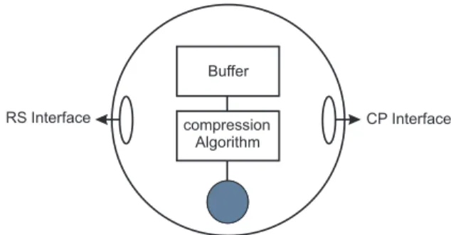
C. Proposed Slave Node Structure
A smart transducer node requires two types of interfaces for accessing its data, a compression algorithm and a buffer to store temporary data to applying in data compression, as in Figure 3. The compression algorithm is responsible for select-ing the relevant data information, generation an asynchronous
flow of data and turning unpredictable the timing instants when the sensor will send its information. However, the time of send-ing a datum is not totally unpredictable due to the minimum and maximum time provided the compression algorithm to the transmission, as will be shown ahead. So, an event-triggered approach would be efficient for the communication of these data.
compression Algorithm
Buffer
RS Interface CP Interface
Fig. 3. Proposal Smart Transducer with a Compression Algorithm
With the larger autonomy provided to the smart sensor, which will now send only relevant data, a great reduction of transferred data, resulting in a smaller bandwidth utilization. This way, it is possible to connect a larger amount of smart sensors to the network. However, they will become more complex and so will demand a larger processing capability. Nevertheless, with the growing technological progress it is possible to design low-cost smart sensors with high processing capabilities. Being so, the compression algorithm embedded in the sensor becomes the main question to be solved within the architectural network of event-triggered smart sensors.
Sensors require two types of interfaces to access the data (RS and CP), where the communication is supported by two different communication models (publisher-subscriber and
client-server):
• RS interface - real-time service interface. It is used to transfer real-time data to the cluster. The data generated by the smart sensors will be published in the net and consumed by the functions of the system.
• CP interface - configuration and planning interface. Through this interface it is possible to identify new nodes connected to the network, to transfer new configuration parameters to the sensor, as values of compression devi-ation, maximum and minimum time for the compression algorithm, besides information as the identification of the sensor in distributed system.
1) Publisher-Subscriber Model: The communication model
used by the RS interface is the real-time publisher-subscriber
model (RTPS). This model of exchanging data favors the
mes-sage exchange with time parameters amid devices between two entities: the publisher, responsible by sending the messages, and the subscribers, responsible for consuming these mes-sages, in case they interest them [9], [10]. The messages sent by the slave node through the RS interface will be consumed by the various functions of the system interested in such data. These messages can be send as commands to actuators or stored in databases in accordance with their requisites; they
can be real-time databases (RTDB) or traditional databases (DB), as shown in Figure 4.
Sensor
RS subscribers pub lisher diagnostic() control_function() sensor_historic() operation_time() Controller DB RTDB RTDBFig. 4. Publisher-Subscriber Model for Proposed Architecture
The data packets sent by smart sensors through the RS interface contain various fields with important information from the smart sensors, which will be consumed by the system functions to different finalities. For example, the
op-eration time() function will access the TIME field and will
store this datum in the real-time database, in order to provide the supervision network the functioning time of a determined smart sensor. The sensor historic() function will access the information in the DATA field, in order to make available the historic file of marks of a smart sensor. The packet’s TAG field is responsible for identifying the sensor; the TYPE field by the identification of the type of the packet to be transferred, while the QUALITY field will contain information about the mark quality of the datum (good, regular, bad, not determined). The CRC field is responsible for controlling the packet’s error. The structure of such packet is illustrated in Figure 5.
TAG TYPE TIME DATA QUALITY CRC
Fig. 5. Struture of a slave node message2) Client-Server Model: The CP interface is accessed
di-rectly by the master node, which can perform configuration activities, parameter passing and reconfiguration of new nodes (Figure 6). As an example of the configuration of a new node connected to the network through the CP interface, master node through function new device() stays monitoring the sys-tem in order to search new nodes connected to the network. Thus, a new smart sensor will ask its inclusion in the system and will be given by the master node, through the function
configure(), the necessary parameters to its correct functioning
in the network. From this point onwards, after confirming the received parameter (confirm()) and having received the authorization to transfer its data (start()), the sensor will start sending its data packets through the RS interface. Figure 7 illustrates this procedure, while Table I present some important system functions.
IV. CASESTUDY
This section presents a case study using the Swinging
Door [11] compression algorithm. The main goal of this
im-plementation is to demonstrate that compression and filtering
CP
configure()...
(Parameters) (Id)Master
Slave
request_inclusion() reconfigure()Fig. 6. Client-Server Model for Proposed Architecture
MASTER
SLAVE
request_Inclusion(ID) configure(parameters) confirm() start() transmit(packet) new_device()Fig. 7. Inclusion proceeding of a nodo new TABLE I SYSTEM FUNCTIONS
Function Interface Definition
request inclusion() CP slave node requisites to master node its inclusion in the network.
configure() CP master node sends configuration pa-rameters of a new slave node.
reconfigure() CP master node sends a reconfiguration to a slave node.
stop() CP master node sends a stop request to a slave node.
start() CP master node authorizes the functioning of a slave node.
check sensor() CP master node verifies if one or more slave nodes are active.
transmit() RS slave node sends a determined packet to the network.
operation time() RS responsible for the time functioning of a smart sensor.
diagnostic() RS responsible by diagnostic information of a smart sensor.
activities can be used in smart sensors, in order to send just the relevant data without losing information integrity.
The Swinging Door algorithm is classified as a compressor with information lost. The basic principle of the Swinging
Door algorithm is to place the first datum marked as the
starting point of the first compression interval. The final point of this compression interval also actuates as final point of the next compression interval [12].
The algorithm contains three main parameters: the compres-sion deviation, the minimum and the maximum comprescompres-sion
time. The algorithm defines a parallelogram as shown in Figure 8. Starting from the initial point, if no received value exceeds the parallelogram until the final point, no intermediate point is stored. In this case, the final point will be stored, and a new starting point will be defined. If some intermediate value exceeds the parallelogram and this value is not synchronous with the minimum time scheduled, then the former value will be stored. The minimum time of compression serves to filter noisy signals. Time V alue Intermediary Points Initial Point End Point t_min t_max compression_deviation
Fig. 8. Swinging Door Algorithm
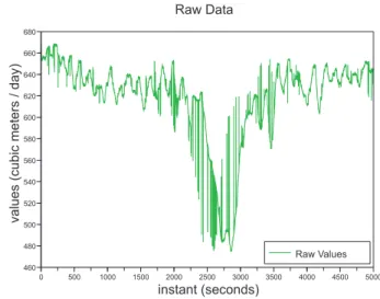
For the first tests we used real data extracted from a real-time gas distribution monitoring system; specifically, we made an option for an outlet variable. For testing effects, a hypothetical situation was considered where the sensor marks were synchronous, generating a new value each second. Having in view a better visualization of the results, 5000 bank values have been used, from a total of 25994 registers. Table II describes some of the results obtained from practical experi-ments. It comes out that when the algorithm’s main parameters are varied, different compression rates are attainable. This way, one can reduce the data traffic nearly 10 times without losing relevant data.
TABLE II
COMPRESSION RATES OF THE EXPERIMENT
Deviation (%) t min (s) t max (s) Compression (%)
0.005 2 10 4.84 0.05 2 3 15.48 0.05 2 4 18.37 0.05 2 10 19.26 0.3 2 3 42.28 0.5 2 4 62.58 0.5 2 10 80.78 1 2 10 86.7 2 2 10 87.92 5 2 10 88.42
It is import to say that the Swinging Door algorithm depends on formerly defined parameters. Thus, the compression rates of the sensors’ values will be dependent on the master node’s established configuration. For example, a pressure sensor will
have a parameter configuration different from that one of a temperature sensor.
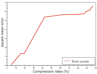
Figure 9 shows the raw data of the smart sensor. Figure 10 shows the reconstructed data, after a compression of the raw data of 88.42% by the implemented algorithm. To the reconstruction of the compacted data, we used the interpolation linear method to assess the lost data with a compression and in order to rescue its times. In Figure 11, it can be visualized the square mean error of the performed experiments. It can be perceived that as long as the compression rates rise, the square mean error generated by the reconstruction of the compacted data also rises.
0 500 1000 1500 2000 2500 3000 3500 4000 4500 5000 460 480 500 520 540 560 580 600 620 640 660 680 Raw Data instant (seconds) values(cubicmeters/day) Raw Values
Fig. 9. Original Data of the Sensor
0 500 1000 1500 2000 2500 3000 3500 4000 4500 5000 460 480 500 520 540 560 580 600 620 640 660 680 Compression Rate of 88.42% instant (seconds) values(cubicmeters/day) Compressed Values
Fig. 10. Data compression of 88,42%
For this particular example, the range of compression be-tween 40% and 90% presents a low variation in square mean error, which characterizes it as a good compression range to be used.
0 10 20 30 40 50 60 70 80 90 100 0 1 2 3 4 5 6 7 Compression rates (%) squaremeanerror Error curves
Fig. 11. Cuves of the square mean errors
V. CONCLUSION
This paper proposes an event-triggered smart sensor net-work architecture. The main feature of the proposed architec-ture is the integration of a data compression algorithm into the smart sensors. This approach saves network bandwidth, because the sensors only send relevant data.
With the achieved results through the realized experiments, it is possible to conclude that the local compression process in each smart sensor can decrease considerably the data exchanges in the communication network. Further work will include the communication control in the event-triggered smart sensor architecture, using schedule techniques with priority to the messages for the purpose of avoiding feasible collisions and packet loss.
REFERENCES
[1] W. Elmenreich, “Time-triggered smart transducer networks,” IEEE
Transactions on Industrial Informatics, vol. 2, pp. 192–199, 2006.
[2] IEEE1451.2, “IEEE Std 1451.2 - Transducer to Microprocessor Communication Protocols and Transducer Electronic Data Sheet (TEDS) Formats, Specification,” September 1997. [Online]. Available: http://standards.ieee.org/catalog/olis/im.html
[3] H. Kopetz and T. Wien, “Omg smart transducer specification II, Specification,” 2003. [Online]. Available: http://www.omg.org/ [4] C.-Y. Chong and S. P. Kumar, “Sensor networks: Evolution,
opportu-nities, and challenges,” in Proceedings of the IEEE, vol. 91, 2003, pp. 1247–1256.
[5] W. Elmenreich and S. Pitzek, “Smart transducers - principles, communi-cations, and configuration,” in Proceedings of the 7th IEEE International
Conference on Intelligent Engineering Systems (INES), 2003, pp. 510–
515.
[6] W. Elmenreich and R. Obermaisser, “A standardized smart transducer interface,” in Proceedings of the 2002 IEEE International Symposium
on Industrial Electronics, vol. 1, 2002, pp. 164–169.
[7] S. Pitzek and W. Elmenreich, “Configuration and management of a real-time smart transducer network,” in IEEE Conference Emerging
Technologies and Factory Automation, ETFA 2003, vol. 1, 2003, pp.
407–414.
[8] K. Ramamritham, “Real-time databases,” International Journal of
Dis-tributed and Parallel Databases, vol. 1, pp. 199–226, 1993.
[9] O. Dolejs, P. Smolik, and Z. Hanzalek, “On the ethernet use for real-time publish-subscribe based applications,” in Proceedings. 2004 IEEE
International Workshop on Factory Communication Systems, 2004, pp.
39–44.
[10] Ocera, “Wp2 architecture specification. deliverable d2.1 -architecture and components integration,” 2002. [Online]. Available: http://mnis.fr/en/support/doc/architecture/
[11] E. H. Bristol, “Swinging Door Trending: adaptive trend recording?” in
ISA National Conf. Proc., 1990, pp. 749–753.
[12] F. Xiaodong, C. Changling, L. Changling, and S. Huihe, “An improved process data compression algorithm,” in Proceedings of the 4th World
Congress on Intelligent Control and Automation, vol. 3, 2002, pp. 2190–
2193.
Erico Le˜ao received the BSc degree in computer science from the Federal University of Piaui, Brazil, in 2005. Currently, he is a MSc student in elec-trical engineering from the Federal University of Rio Grande do Norte, Brazil. His research interests include time communication systems, and real-time distributed system architectures.
Luiz Affonso Guedes has a graduate in electrical engineering from the Federal University of Par´a, Brazil, in 1987, and PhD degree in Computer Engi-neering from State University of Campinas, Brazil, in 1999. Since 2003, he is an associate professor in the Department of Computer Engineering and Automation at Federal University of Rio Grande do Norte, Brazil. His main research interests include Communication System to Industrial Application and High Level Programming Languages to Indus-trial Automation.
Francisco Vasques (M’00) received the BSc degree in Electrical Engineering from the University of Porto, Portugal, in 1987 and both the MSc and PhD degrees in Computer Science from LAAS-CNRS, Toulouse, France, in 1992 and 1996. Since January 2004, he is Associate Professor at the Mechanical Engineering Department of the University of Porto, where he is at the head of the Master Programme on Mechanical Engineering.
Prof. Francisco Vasques is author or coauthor of more than 100 technical papers in the areas of real-time systems and industrial communication systems. His current research in-terests include real-time communication systems, industrial communications, fault-tolerant systems, and real-time system architectures. Since 2007, he his Associate Editor of the IEEE Transactions on Industrial Informatics for the topic on Industrial Communications.