U
NIVERSIDADE DE
L
ISBOA
Faculdade de Ciˆencias
Departamento de Inform´atica
DESIGN AND IMPLEMENTATION OF A MODULAR
SCHEDULING SIMULATOR FOR AEROSPACE
APPLICATIONS
Rui Pedro Ormonde Silveira
PROJETO
MESTRADO EM ENGENHARIA INFORM ´
ATICA
U
NIVERSIDADE DE
L
ISBOA
Faculdade de Ciˆencias
Departamento de Inform´atica
DESIGN AND IMPLEMENTATION OF A MODULAR
SCHEDULING SIMULATOR FOR AEROSPACE
APPLICATIONS
Rui Pedro Ormonde Silveira
PROJETO
Trabalho orientado pelo Prof. Doutor Jos´e Manuel de Sousa de Matos Rufino e co-orientado pelo Mestre Jo˜ao Pedro Gonc¸alves Crespo Craveiro
MESTRADO EM ENGENHARIA INFORM ´
ATICA
Acknowledgments
First i would like to say a great “Thank you” to my advisors Prof. Jos´e Rufino and Jo˜ao Craveiro because without them this our would never be complete. Their time, patience, guidance were crucial.
To all colleagues the friends at the university that have always been there for support, discussions and friendship. I would like to thank Fufinha, Sandrinha, Kleo, Gil, Reiz˜ao, Mano, Craveiro, Dias, Mac, Krypton, Ritz, Kelly, Chimy, Poli, Cabaco, S. Miguel, Azedo, B´arbara, Rodrigo, Espanhol and many others that don’t come to mind right now but still are in my memory.
Last but not least to all the biggest “Thank you” of all goes to my family that have supported me in the best and the worst moments, didn’t even need to look back, i know they have my back, now and always.
This work was partially supported by FCT/ ´Egide (PESSOA programme), through the trans-national cooperation project SAPIENT (Scheduling Analysis Principles and Tool for Time- and Space-Partitioned Systems; homepage: http://www.navigators.di.fc.ul.pt/wiki/ Project:SAPIENT).
This work was partially supported by the EC, through project IST-FP7-STREP-288195 KARYON (Kernel-Based ARchitecture for safetY-critical cONtrol; homepage: http://www.karyon-project. eu).
This work was partially supported by FCT (Fundac¸˜ao para a Ciˆencia e a Tecnologia), through the LaSIGE research unit strategic project (PEst-OE/EEI/UI0408/2011).
Glossary
CNES Centre National d’ ´Etudes Spatiales (the French nati-onal space agency)
DAS Distributed Application Subsystem
DECOS Dependable Embedded Components and Systems
EDF Earliest Deadline First
ESA European Space Agency
HS Hierarchical Scheduling
IMA Integrated Modular Avionics
LLF Least Laxity First
PMK Partition Management Kernel
RM Rate-Monotonic
SPIRIT Strongly Partitioned Integrated Real-tIme sysTem
Abstract
Real-time systems are required to produce results from each task in time, according to the urgency of each one. Since the 1970s researchers try to obtain ways to coordinate the execution of tasks to meet all deadline, by using scheduling algorithms. Although the majority of these algorithms required an extensive work from those who created them, they are simple to understand. One of the oldest is the Earliest Deadline First algorithm, which attributes higher priority to the most urgent tasks.
Due to their characteristics, some systems obey to more complex models; this is the case of aerospace systems. These systems require full isolation between functionalities. The functions, composed of tasks (processes), are logically grouped into partitions. To ensure separation in the time domain, a two level scheduling scheme is introduced. The first level determinates the time windows to assign to each partition; in the second level, tasks in each partition compete among them for the execution time assigned to the latter. The scheduling algorithms used in each level do not need to be the same; in the second level, each partition may even employ a different algorithm to schedule its tasks.
After studying what currently exists we have decided to guide our work to partitions and hierarchical scheduling because it is where we see producing better results and solutions for future systems. Using design patterns as well as Java properties such as inheritance and polymorphism we were able to obtain a solution that after implemented allows users to simulate the execution of a system defined by them. The tool allows obtaining events and showing them to the user and giving feedback, these events represent the basic functionalities of a real-time system, such as, job launch and jod deadline miss and others. These results can be shown in textual form or use other applications of results visualization.
Resumo
Sistemas tempo-real tˆem de produzir os resultados esperados de cada tarefa atempadamente de acordo com a urgˆencia de cada uma. Desde os anos 70 tentam-se obter formas de coordenar a execuc¸˜ao das tarefas para cumprir todos os prazos atrav´es de algoritmos de escalonamento. Na sua maioria estes algoritmos apesar de terem requerido um extensivo trabalho por parte de quem os criou s˜ao simples de compreender. Um dos mais antigos ´e o algoritmo “Earliest Deadline First”, que consiste em dar maior prioridade `as tarefas mais urgentes. Alguns sistemas devido `as suas ca-racter´ısticas particulares obedecem a modelos mais complexos. ´E o caso dos sistemas aeron´auticos onde ´e necess´ario manter o isolamento entre as funcionalidades. As func¸˜oes s˜ao agrupadas logica-mente em contentores denominados partic¸˜oes. Para garantir essa separac¸˜ao no dom´ınio do tempo introduz-se um esquema de escalonamento a dois n´ıveis. Um primeiro que determina as janelas temporais a dar a cada partic¸˜ao e um segundo n´ıvel onde est˜ao as partic¸˜oes e respectivas func¸˜oes. Os algoritmos de escalonamento utilizados em cada n´ıvel n˜ao tem de ser iguais; no segundo n´ıvel, cada partic¸˜ao pode usar um algoritmo diferente. Ap´os estudar o que actualmente existe decidimos orientar o nosso trabalho para partic¸˜oes e escalonamento hier´arquico pois ´e de onde poderemos vir a obter melhores resultados e soluc¸˜oes para sistemas futuros. Fazendo uso de padr˜oes de de-senho, bem como caracter´ısticas do Java, tais como heranc¸a e polimorfismo conseguimos obter uma soluc¸˜ao que ap´os implementada permite aos seus utilizadores simularem a execuc¸˜ao de um sistema que estes definam. Permite tamb´em obter os eventos e com estes mostrar ao utilizador o que o simulador fez em cada momento do sistema podendo estes resultados ser exibidos em formato textual ou fazer uso de outras aplicac¸˜oes de visualizac¸˜ao de resultados.
Resumo Alargado
Sistemas tempo-real tˆem de produzir os resultados esperados de cada tarefa atempadamente de acordo com a urgˆencia de cada uma. Desde os anos 70 tentam-se obter formas de coordenar a execuc¸˜ao das tarefas para cumprir todos os prazos atrav´es de algoritmos de escalonamento. Na sua maioria estes algoritmos apesar de terem requerido um extensivo trabalho por parte de quem os criou s˜ao simples de compreender. Um dos mais antigos ´e o algoritmo “Earliest Deadline First”, que consiste em dar maior prioridade `as tarefas mais urgentes.
Para melhor aproveitar os recursos f´ısicos dos actuais e futuros computadores, e para diminuir o n´umero de computadores necess´arios para desempenhar a mesma tarefa anteriormente desem-penhada por diversos computadores, tem vindo a surgir formas de agregar funcionalidades dentro do mesmo sistema.
Sendo que se est´a a agregar func¸˜oes ´e necess´ario assegurar o que anteriormente era assegurado pelas func¸˜oes estarem fisicamente separadas pelo hardware, o isolamento no tempo e no espac¸o. Estas func¸˜oes anteriormente separadas fisicamente passar˜ao agora a ser vistas pelo sistema como componentes. O isolamento entre estes componentes ´e crucial, tanto ao n´ıvel do tempo, em que a execuc¸˜ao de um deles (componente) n˜ao interfira com o tempo de execuc¸˜ao nem com o in´ıcio da execuc¸˜ao de outro componente e ao n´ıvel do espac¸o que o enderec¸amento e espac¸o de mem´oria n˜ao coincida com o de outro componente.
Devido ao aumento constante da complexidade dos sistemas e de num futuro pr´oximo estes mesmos sistemas venham a possuir mais de dois n´ıveis hier´arquicos, a ferramenta que estamos a construir j´a est´a equipada para que se possa simular a execuc¸˜ao de um sistema com o n´umero de n´ıveis que se desejar.
Para conseguir construir um n´umero indeterminado de n´ıveis, e como na an´alise desta fer-ramenta decidimos concretizar esta ferfer-ramenta em Java e fazendo uso de padr˜oes de desenho como o padr˜ao Composite permite ao sistema abstrair uma tarefa e uma partic¸˜ao como uma tarefa abstrata denominada AbstractTask. Assim sendo, os escalonadores implementados poder˜ao esca-lonar tanto tarefas como partic¸˜oes, sem ser necess´aria a sua diferenciac¸˜ao. Com esta abstrac¸˜ao ´e poss´ıvel construir simulac¸˜oes de sistemas em que na sua ´arvore hier´arquica tenta um n´umero indeterminado de n´ıveis, bem como n˜ao seja necessariamente balanceada (´arvore n˜ao balanceada significa que no mesmo n´ıvel hier´arquico n˜ao necessita haver apenas s´o partic¸˜oes ou apenas s´o tarefas, pode haver uma mix´ordia de ambos). O uso do padr˜ao de desenho Strategy permite que na
implementac¸˜ao de novos algoritmos de escalonamento n˜ao haja dependˆencia de como funciona o dom´ınio da aplicac¸˜ao.
A soluc¸˜ao apresentada neste trabalho faz uso de propriedades fornecidas pelo Java, tais como polimorfismo e heranc¸a. O uso de programac¸˜ao orientada a objetos facilitou a concretizac¸˜ao da soluc¸˜ao. Desde o in´ıcio que foi nosso objetivo concretizar uma soluc¸˜ao de percec¸˜ao simples, modular (separar, distanciar e organizar as v´arias partes referentes ao projeto de forma para a que possam funcionar separadamente, que uma alterac¸˜ao possa ser efectuada apenas em um lugar e que funcionem de forma independente) e flex´ıvel (como estamos a trabalhar na ´area do tempo-real, em que muitos outros investigadores ao mesmo tempo est˜ao a trabalhar, ´e boa decis˜ao permitir que dentro dos poss´ıveis a nossa ferramenta possa interagir com outras ferramentas).
Para estruturar este projecto tivemos de comec¸ar por implementar os algoritmos simples de escalonamento, como forma de testar. Ap´os ter os algoritmos simples, e mais f´aceis de concretizar comec¸amos a executar pequenas simulac¸˜oes para testar que a nossa implementac¸˜ao do algoritmo estava correcta. Assim que t´ınhamos o funcionamento b´asico dos algoritmos simples testado foi altura de comec¸ar a tentar criar um segundo n´ıvel no nossa sistema. Ao conseguirmos ter a fer-ramenta a funcionar com dois n´ıveis comec¸a o verdadeira desafio deste projecto, comec¸a a ser necess´ario abstrair as diferenc¸as entre uma partic¸˜ao e uma tarefa (internamente, e para o sistema apenas). Para conseguir o pretendido foi criada a classe abstracta AbtractTask, que ´e estendida por ambas tarefas e partic¸˜oes e que regula o funcionamento base de ambas. Ficando apenas por definir o que for espec´ıfico de ambas na pr´opria classe. Desta forma, quando for criada uma simulac¸˜ao internamente ser˜ao criadas instˆancias de AbstractTask e ser´a responsabilidade do polimorfismo em tempo de execuc¸˜ao diferenciar ambos atrav´es da sua tarefa “pai”a fim de executar com exatid˜ao os objetivos de ambos.
Criando mais n´ıveis, e usando os princ´ıpios do escalonamento hier´arquico, deparamo-nos com o obst´aculo de como fazer para determinar a execuc¸˜ao de uma unidade de tempo e como propagar essa informac¸˜ao pela hierarquia. A soluc¸˜ao a que cheg´amos faz com que o tempo seja indepen-dente da hierarquia, apenas pertencente ao sistema, sistema este que controla o n´ıvel mais baixo da hierarquia, o n´ıvel zero. Assim sendo, quando o sistema notifica a passagem de uma unidade de tempo, essa informac¸˜ao chega ao escalonador do n´ıvel zero que vai `a sua fila de instˆancias de tarefas em lista de espera (podendo estar nesta instancias de tarefas e de partic¸˜oes) e escolhe a que tem maior prioridade segundo o algoritmo escolhido por este n´ıvel. Esta instˆancia escolhida vai propagar essa informac¸˜ao `a sua tarefa “pai” (tarefa da qual esta instˆancia resultou), caso esta seja instˆancia de tarefa, reduz uma unidade `a capacidade restante e o sistema passa mais uma unidade de tempo, caso esta instˆancia seja de uma partic¸˜ao n˜ao s´o ´e diminu´ıdo uma unidade `a capacidade restante desta partic¸˜ao bem como recomec¸a o processo de selecc¸˜ao da instˆancia com maior priori-dade neste escalonador. E assim sucessivamente at´e que termina numa tarefa, pois neste esquema as “folhas” da ´arvore tem de ser todas instˆancias de tarefas.
Agora que conseguimos executar um sistema com um n´umero variado de n´ıveis ´e altura de registar os eventos mais importantes que ocorrem durante esse per´ıodo de tempo. Para tal, num
pacote `a parte, cri´amos um Logger que regista os eventos que foram notificados pelo dom´ınio da aplicac¸˜ao. Inicialmente, e ´e uma vers˜ao disponibilizada para os utilizadores perceberem que even-tos est˜ao a ser lanc¸ados pelo sistema, esta classe Java recebia os eveneven-tos e criava uma descric¸˜ao textual para o utilizador poder seguir a passo e passo as decis˜oes que a aplicac¸˜ao estava a fazer em cada momento da execuc¸˜ao da simulac¸˜ao. Posteriormente, e querendo justificar as nossas decis˜oes de desenho, bem como justificar a modularidade e a flexibilidade em estender a nossa aplicac¸˜ao, j´a um pouco fora do ˆambito deste projecto foi criada uma nova classe com o nome de GraspLogger. Esta nova classe produz como resultado um ficheiro grasp que ´e o necess´ario para a execuc¸˜ao de um desenhador gr´afico que permite visualizar a passo e passo que tarefas e partic¸˜oes est˜ao ativas em cada momento. Quando este ficheiro ´e produzido, fazendo uso da aplicac¸˜ao Grasp podemos visualizar os resultados da simulac¸˜ao que foi efectuada.
Contents
Glossary vii
List of Figures xxi
1 Introduction 1
1.1 Motivation . . . 1
1.2 Goals . . . 2
1.3 Document Outline . . . 2
1.4 Contributions . . . 2
2 State of the art 5 2.1 Real-Time Scheduling Theory . . . 5
2.2 Scheduling Algorithms . . . 5
2.2.1 Fixed task priority scheduling algorithms . . . 6
2.2.2 Fixed job priority scheduling algorithms . . . 6
2.2.3 Dynamic job priority scheduling algorithms . . . 6
2.3 Time- and space-partitioned systems (TSP) . . . 7
2.3.1 ARINC 653 Specification . . . 7
2.4 Time- and Space-Partitioned Systems and Architectures . . . 8
2.5 Hierarchical Scheduling . . . 9
2.6 Scheduling Simulator Tools . . . 10
2.6.1 Cheddar . . . 10
2.6.2 Schedsim . . . 10
2.6.3 Scheduling Simulator for Real-Time Systems . . . 11
2.6.4 MOSS . . . 11 2.6.5 MAST 2 . . . 11 2.6.6 SPARTS . . . 11 2.6.7 CARTS . . . 11 2.6.8 Grasp . . . 12 2.6.9 SymTA/S . . . 12
3 Problem analysis and solution design 13 3.1 Introduction . . . 13 3.2 Analysis . . . 13 3.3 Design . . . 15 3.3.1 Composite Pattern . . . 16 3.3.2 Strategy Pattern . . . 16
3.3.3 N -level Hierarchy and Polymorphism . . . 17
3.3.4 Observer and Visitor Patterns . . . 19
3.4 Summary . . . 19
4 Implementation and tests 23 4.1 pt.ul.fc.di.lasige.simhs.domain Package . . . 23 4.1.1 pt.ul.fc.di.lasige.simhs.domain.events Package . . . 25 4.1.2 pt.ul.fc.di.lasige.simhs.domain.schedulers Package . . . 25 4.2 pt.ul.fc.di.lasige.simhs.services Package . . . 25 4.2.1 pt.ul.fc.di.lasige.simhs.services.xml Package . . . 25 4.3 pt.ul.fc.di.lasige.simhs.simulation Package . . . 25 4.4 com.example.hssimextensions Package . . . 26 4.5 Tests . . . 26 4.5.1 Two-level hierarchy . . . 26
4.5.2 Unbalanced three-level hierarchy . . . 27
4.6 Summary . . . 29
5 Conclusion 31
Bibliography 35
List of Figures
2.1 ARINC 653 Architecture . . . 8 2.2 AIR Architecture . . . 9 3.1 Domain Model . . . 14 3.2 Traditional one-level system domain model . . . 15 3.3 Two-level hierarchical scheduling system domain model . . . 16 3.4 N-level hierarchical scheduling system using the Composite pattern . . . 17 3.5 Scheduling algorithm encapsulation with Strategy pattern . . . 18 3.6 Sequence diagram for the schedule tickle operation . . . 19 3.7 Logger (Observer and Visitor patterns) . . . 20 4.1 Packages Diagram . . . 23 4.2 Two-level system . . . 27 4.3 Results of the two-level system . . . 27 4.4 Three-level system . . . 28 4.5 Results of the three-level unbalanced system . . . 29
Chapter 1
Introduction
1.1
Motivation
Real-time systems, such as, Aerospace systems have strict dependability and real-time require-ments, as well as a need to flexible resource allocation and obey to complex designs to complete their functions. In order to improve such systems a possible solution might be to aggregate several functions in one computer instead of several computers communicating between them. But, it is necessary the isolation between said functions, to which logical container corresponding to each function will be called “partition”. Time- and Space- Partitioned (TSP) systems may integrate heterogeneous functions with different criticalities and origins. A TSP system requires isolation on the space and time domain. To ensure space isolation we must assure that access memory space will not interfere with other running application. To ensure time isolation a delay on one partition can not affect the normal behaviour of the other partitions. Only by assuring these two properties is feasible to aggregate totally different functions on the same platform, otherwise vi-olation of deadline might occur, and on real-time systems that can be problematic. Since each partition may have very strict requirements with the timely execution of their functions as they run on real-time constraints, it is vital to properly simulate them before launch. Simulating the execution of aerospace systems can help to decide how to construct and dimension the systems in order to avoid time failures during the execution. In order to structure those systems we require to assure the correct isolation within the system, such as, isolation of time attributed to each part of the system, and assuring delay in one part will not cause disturbance on the remaining part of the system. Aerospace systems are also partitioned by levels under a hierarchical scheduling (HS) properties which assures that the lower level will be responsible for controlling the time attributed to every part of the system directly on top of it, therefore, controlling which part shall execute on each instant and for how long it should, assuring TSP time isolation for and indeterminate amount of TSP systems on top of TSP systems. It is our objective to explore the application and growth of HS with more than two levels on real-time applications such as, aerospace systems.
Most theory and practice focus on two-level hierarchies, with a root scheduler managing parti-tions, and a local scheduler in each partition to schedule respective tasks. By task for the purposes
Chapter 1. Introduction 2
of this work we will understand the triple (C, T, D) where as an abstraction C is the worst-case execution time, T is the minimum inter-arrival time (or period) and D is the relative deadline. In our tool we will support an arbitrary number of levels in the hierarchy.
To help understand how to build systems with hard real-time properties we plan to build hsSim, a simulation tool for the real-time research community as well as aerospace developers such as ESA. We focus on supporting well-known and widely used models such as periodic task model. hsSim pursues an open, reusable, extensible and interoperable tool.
1.2
Goals
The goal of this project is to design and develop a Java simulator that performs as it was a scheduler using a scheduling algorithm observing the following properties:
• support most common scheduling algorithms and allow expansion with user-defined algo-rithms;
• allow users to construct simulations of hierarchical scheduling systems with an arbitrary number of levels;
• accurately simulate the behaviour of the system throughout the time by logging all the events occurred;
• easily be extended taking advantage of Object-Oriented Analysis and Design principles such as inheritance and polymorphism applied in this conception;
The results produced will help us and the other researchers in the field to study the implications of using a time-and space partitioning system with hierarchical scheduling model.
1.3
Document Outline
The present report is structured as follows:
Chapter 2 - Introduction to base concepts, and description of the state of the art. Chapter 3 - Problem analysis and solution design.
Chapter 4 - Implementation decisions and tests. Chapter 5 - Conclusion and future work.
1.4
Contributions
With the goal of validating and disseminating the present ideas, the work of this thesis generated the following refereed publication:
1. J. P. Craveiro, R. O. Silveira, and J. Rufino, “hsSim: an extensible interoperable object-oriented n-level hierarchical scheduling simulator” in 3rd International Workshop on Analysis
Chapter 1. Introduction 3
Tools and Methodologies for Embedded and Real-time Systems (WATERS 2012), Pisa, Italy, Jul. 2012 [1].
Chapter 2
State of the art
2.1
Real-Time Scheduling Theory
Real-time scheduling systems have the capacity of executing actions within pre-specified time intervals. In order for a system to be classified as real-time it must contain at least one real-time application/task. For the purposes of this work, task will understand the triple (C, T, D) where as an abstraction C is the worst-case execution time, T is the minimum inter-arrival time (or period) and D is the relative deadline. These systems can be classified as real-time where timing failures need to be avoided. There are two types of real-time, hard real-time where a timing failure can be catastrophic to the good functioning of the system or soft real-time where occasional timing failures are acceptable and will not cause major disturbances on the normal functioning of the system [2, 3].
To schedule the tasks it is used scheduling algorithms who will be responsible to determine which job will be executed next. A job is an infinite sequence of repetition of the task through time with repetition according to the period. There can identified two distinct types of deadlines, the relative deadline which is the one defined on the task and the absolute which is ready time plus the relative deadline. The ready time it is the unitary time that a task is launched and goes to the ready state. By resorting to scheduling simulations to check if a specific set of tasks is feasible.
2.2
Scheduling Algorithms
Scheduling is a definition of how to allocate the available resources and make use of them to execute task timely. Even when having enough resources, they must be allocated properly to ensure the timings of the most tasks are met. Scheduling defines how a resource is shared by different activities in the system, according to a given policy (Algorithm) [2, 4, 5].
We will analyse below fixed and dynamic priority scheduling algorithms and give and example of each that will be implemented in our simulation tool.
Chapter 2. State of the art 6
2.2.1
Fixed task priority scheduling algorithms
In fixed task priority scheduling algorithms, each task has a single fixed priority applied to all of its jobs. The most common example is Rate-Monotonic (RM).
The RM scheduling algorithm proposed by Liu and Layland in 1973 [3] attributes priority based on the periodicity of the tasks. The priority is inversely proportional to the periodicity of the tasks, meaning that lower period tasks will be given higher priorities. This algorithm is considered to be one of the best for periodic tasks.
Before execution some simple tests can be applied to the set of tasks to check the schedulabil-ity, applying schedulability tests. This test might not be sufficient to ensure the schedulability so there is a exact test that can be applied to the task set but requires that all the period are multiple of each other.
2.2.2
Fixed job priority scheduling algorithms
Fixed job priority scheduling algorithms means each job of the same task may have a different priority, which is, nevertheless fixed throughout the jobs existence. An example is the Earliest Deadline First (EDF) [4].
EDF is a dynamic scheduling algorithm proposed by Liu and Layland in 1973 [3]. A job priority queue is created to manage which job will execute next. The queue, as the name of the algorithm suggests, orders the jobs by absolute deadlines, giving higher priority to the earliest deadline. A job will be assigned the highest priority if the deadline of its current job is the earliest, and will be assigned the lowest priority if the deadline of its current job is the latest. Such a method of assigning priorities to the jobs is a dynamic one, in contrast to a static assignment in which priorities of jobs do not change with time [3].
EDF is a algorithm initially thought for uniprocessor, by receiving a collection of independent jobs characterized by an arrival time, a worst case execution time (WCET) and a deadline, the EDF will schedule this collection of jobs such that they all complete by their deadlines. In the triple (C, T, D) deadline corresponds to the D, the WCET corresponds to the C and the arrival time is a math calculation based on the period, the T letter. In this specific algorithm the deadline is the most important measure taken in consideration to decide the sequence of tasks to be executed. The closer we get to the deadline the highest priority a task will be given in order to best try to arrange the tasks which still need some time to finish their execution.
2.2.3
Dynamic job priority scheduling algorithms
Dynamic priority scheduling algorithms calculate the priorities during the execution of the system and a single job may have different priorities at different times. An example is Least Laxity First (LLF) [6].
The LLF scheduling algorithm assigns a priority to a job according to its execution laxity. The laxity is the difference of remaining execution time to the deadline. The passage of time will cause
Chapter 2. State of the art 7
the priorities to be recalculated causing the laxity of the ready tasks to decrease with each clock tick. A ready task is a task that have all the requirements met to execute, just awaiting CPU time to do so.
2.3
Time- and space-partitioned systems (TSP)
Time- and space-partitioned systems (TSP) [7] are a way to integrate a heterogeneous set of func-tions (different criticalities and origins) in a shared computing platform, fulfilling their funcfunc-tions without interference. Spatial partitioning [8] ensures that it is not possible to an application to access the memory space (both code and data, as well as execution context - stack) of another ap-plication running on a different partition. Temporal partitioning ensures that the activities in one partition do not affect the timing of the activities in any other partition, a delay on the execution of a specific partition will only affect his own, the rest will execute without delays. Applica-tions are separated into logical partiApplica-tions, scheduled according to predefined partition scheduling algorithms.
Each partition will make a request for execution of the jobs it has, never disclosing or interfer-ing with the other partitions at any time. This assures that if for any reason some partition misses its deadline will not interfere with the other partitions time frames or deadlines.
2.3.1
ARINC 653 Specification
The ARINC 653 specification, adopted by the Airlines Electronic Engineering Committee in 1996, is a fundamental block from the Integrated Modular Avionics (IMA) definition, where the parti-tioning concept emerges for protection and functional separation between applications, usually for fault containment and ease of validation, verification, and certification.
In traditional avionics system architecture each function had his own dedicated computer re-sources. The Integrated Modular Avionics (IMA) [9] concept emerged with a view of a partitioned system that hosts multiple avionics functions of different criticalities on a shared computer plat-form. The usage of IMA allowed avionics to reduce the weight and power consumption because they were able to reduce the number of computers needed in each aircraft.
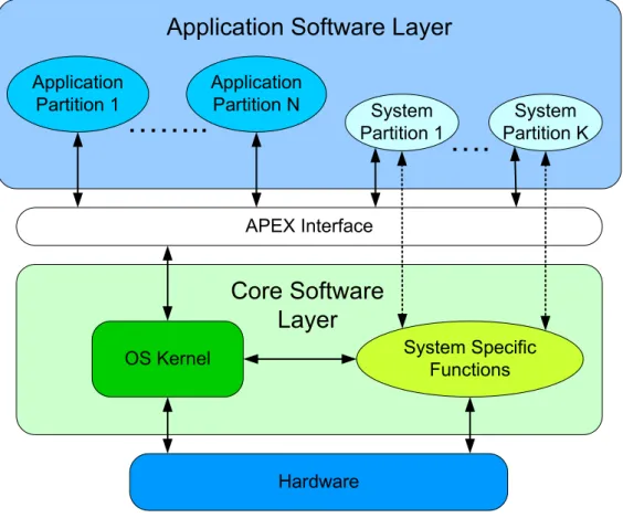
The architecture of a standard ARINC 653 system is sketched in Figure 2.1. At the application layer is executed in a confined context, a partition. This layer may include system partitions to manage interactions with hardware devices. Each application consists of one or more processes and can use only the services provided by the application layer (APEX) interface.
The execution environment provided by the OS Kernel module must administrate the pro-cess scheduling management, time and clock management, and inter-propro-cess synchronization and
Chapter 2. State of the art 8
Figure 2.1: ARINC 653 Architecture
2.4
Time- and Space-Partitioned Systems and
Architec-tures
Time- and Space-Partitioned systems (TSP) and architectures are a subject of high interests in the research done in academic institutions since it is a recent subject on the area. Since not much is known yet as how to better implement TSP on the systems we are trying to take better advantage of the hardware. A lot of research it is still being done around to world to understand the capabilities and the impact it will bring to the construction of future systems.
The Dependable Embedded Components and Systems [10] (DECOS) architecture is combin-ing federated and integrated systems. DECOS aims for both automotive and aerospace domains. In this architecture jobs are separated according to functionality and criticality by Distributed Ap-plication Subsystem (DAS). These jobs may even be distributed by different components (or node computers). Computation resources inside each node are time- and space-partitioned like any other TSP architecture.
Strongly Partitioned Integrated Real-tIme sysTem (SPIRIT) µKernel [11] provides the core software layer of a TSP system. Temporal partitioning is ensured by a distance constrained cyclic partition scheduler with the help of APEX interface imposing a fixed amount of processing time [12].
Chapter 2. State of the art 9
Xtratum [13] developed at the Polytechnical University of Valencia under a contract from Centre National d’Etudes Spatiales(CNES, the French space agency), first started as a nanokernel satisfying the requisites of a hard real-time system. Spatial partition is not fully guaranteed since it is up to the partitions operating system to coordinate themselves. XtratuM was redesigned to fulfil critical real-time requirements. It features TSP capabilities and fixed cyclic scheduling of partitions.
AIR [9] has grown because of the interest that the space industry took on adopting TSP con-cepts, namely the European Space Agency (ESA). The AIR architecture is shown on Figure 2.2. The AIR Partition Management Kernel (PMK) is the unit responsible for the assigning and cyclic rotation of the partitions (cyclic attribution of processing time to each partition), as well as com-munication between them. At each clock tick a partition scheduler consults the scheduling table to detect if a partition preemption point has been reached, and if it has then perform the context switch between the active partition and the one beeing activated.
Deos [14] a real-time operating system which addresses the issues of high robustness and formal certifiability for avionics and safety critical applications. Deos supports popular avionics standards and other certifiable features allowing users to customize their Deos environment by choosing from a variety of optional modules such as the ones for ARINC 653. Deos is a commer-cial tool therefore the information we can acquire about it is not much due to the confidentiality of its work.
Figure 2.2: AIR Architecture
2.5
Hierarchical Scheduling
Software embedded computer systems complexity is increasing each year. A way to deal with this complexity is to subdivide the software into components where each component has its own purpose. The difficulty when decomposing a software system into components is typically driven
Chapter 2. State of the art 10
different sources require logical isolation. Different functions within the same system should be-long to different components because one function should not be able to obtain information about another component. To ease the certification process each component should not have functions with more than one criticality level [15].
After creating the components to better execute this software system it is time to organize them on a tree based model. This will help the users visualize how each scheduler inside each component will chose which one will execute next and so on. Since components are independent each one will require an inside scheduler, to scheduler their tasks. In case of having one compo-nent inside of another compocompo-nent then the main compocompo-nent’s scheduler is responsible to attribute execution time to his inside component.
2.6
Scheduling Simulator Tools
2.6.1
Cheddar
Cheddar [16] is a free real-time scheduling tool designed to check the task temporal constraints of a real time application/system. Cheddar is also used for education purposes.
Cheddar is composed of two independent parts: an editor used to describe a real time appli-cation/system, and a framework. The editor allows you to describe systems composed of several processors which own tasks and shared resources. The framework includes many schedulability tests and simulation tools (tools that allow users to run simulations, of specific systems they de-fine). Schedulability tests can be applied to check if a set of tasks it is schedulable or not. When schedulability tests results are not definitive (meaning the results obtained are not conclusive on the schedulability of that specific set of tasks beeing analized), the studied application can be ana-lyzed with scheduling simulations. Cheddar provides a way to define “user-defined schedulers” to model applications/systems (e.g. ARINC 653). Although this tool allow us to divide our structure, it still lacks some concepts of hierarchical scheduling.
2.6.2
Schedsim
Schedsim [17] is an open-source scheduling analysis tool. At present it handles periodic tasks, but not aperiodic, nor sporadic jobs.
The current version of the tool implements the simpler scheduling algorithms like: Earliest Deadline First (EDF) [3], Rate-Monotonic (RM) [3]. This scheduler simulator can be used for education purposes or as a basic prototyping tool.
This tool has yet no support for hierarchical scheduling, which is one of our biggest concerns when we are building hsSim.
Chapter 2. State of the art 11
2.6.3
Scheduling Simulator for Real-Time Systems
In 2005 Gis´elia Cruz built a modular scheduling simulator tool. Built in Java, support to the existing scheduling algorithms, but can only have one level of scheduling and do not support TSP. The main difference from what we want to accomplish and this work it is the ability to construct a multiple layer hierarchy and in each of those create partition to logically separate their functionalities. The user will be able to configure how many layers he wish to build, from one to an indeterminate number of them [18].
2.6.4
MOSS
MOSS Scheduling Simulator created in 2001 illustrates the behaviour of scheduling algorithms against a simulated mix of process load. Allows configuration of number of process, blocking time of each process. At the end a statistical summary will be presented of the simulation, even allowing creation of new algorithms to be used in the simulations [19].
2.6.5
MAST 2
MAST 2 [20] uses a model that describes the timing behaviour of real-time systems which is analysed via schedulability analysis techniques. MAST 2 introduces modelling elements for vir-tual resources, abstracting entities that rely on the resource reservation paradigm. The focus of resources it is not our main objective, it is however our objective to study the utilization bounds of real-time systems with properties similar to the ARINC 653 standard but not stopping there, always pushing forward on the complexity of those systems.
2.6.6
SPARTS
SPARTS is a real-time scheduling simulation focused on power-aware scheduling algorithms. Its simulation engine is optimized by replacing cycle-step execution for an event-driven approach centred on the intervals between consecutive job releases. Although a few similarities on how to define task, the support for different scheduling algorithms the purpose of this work is the power aware when our main purpose is to check how resources will accommodate the time needs of our system. Hierarchical scheduling support is not mentioned, so we assume can not know for sure if they do support it [21].
2.6.7
CARTS
CARTS is an open source compositional analysis tool for real-time systems, which automatically generates the component’s resource interface. This tool does not perform simulation, so it relies strongly on the author’s theoretical results. Although it is implemented in Java, does not take advantage of latest object-oriented characteristics (inheritance, polymorphism, encapsulation -
es-Chapter 2. State of the art 12
extend this tool as our project and start to develop hsSim from scratch in order to have a strong, and well organized foundation to future development and extension of our own tool [22].
2.6.8
Grasp
Grasp is a trace visualization toolset. It supports the visualization of multiprocessor hierarchical scheduling traces. Traces are recorded from the target system into Grasp’s own script-like format, and displayed graphically by the Grasp Player. The Grasp toolset does not support simulation and supports only a two-level hierarchy, where as hsSim simulates hierarchical systems with an arbi-trary number of levels. The mention of Grasp in this work is to ensure our tool’s interoperability features with other already existing tools, which in this case is a graphical display trace [23].
2.6.9
SymTA/S
SymTA/S is a model-based timing analysis and optimization solution with support to ARINC 653. No specific mention is made to hierarchical scheduling, thus we can only assume it supports a two-level hierarchy. A big amount of analysis tools seems to be available on SymTA/S but due to its proprietary nature, we cannot fully assert its capabilities and it does not serve our purpose for open, reusable, extensible tools for academic/scientific research [24].
Chapter 3
Problem analysis and solution design
3.1
Introduction
The focus of the creation of our tool is to create a tool which is flexible and modular, to en-sure expansion of the work it is already done. This tool focus on the simulation of a diversified group of real-time systems. Group of systems which include mono-processor standard one level systems, and time- and space- partitioning (TSP) systems which have a two level hierarchy in mono-processor platform, and now what we see as new, the ability for the user to create a mix of the previous described systems on a single processor platform. So a system created by a user using this tool can take advantage of TSP partitioning as well as creating an undetermined number of levels if the user desires. This tool will allow the simulations to create totally independent par-titions with their own task set that will be known by no one but themselves we grant the properties required by TSP. Something that is new to this tool is the possibility of creating an undetermined number of levels on top of each other, where each partition can have its own scheduling algorithm associated, not being the same on all partitions. This creation of levels creates a hierarchical tree that does not need to be balanced and which the lower level will attribute execution time to one of the upper levels without know which jobs they have to execute allowing different criticalities through the partitions.
Will be presented the process stages of hsSim a simulation tool for the aerospace community with the goals of open, reusable, extensible and interoperable tool. Modularity is essential, so we carefully used application of the object-oriented paradigm and software design patterns to reach it. The employment of these design patterns helped us overcome some difficulties found and grant easier ways to extend and create new modules to interact with the tool.
3.2
Analysis
Our main objective is to run simulations therefore that is our main use case scenario, where a user introduces a set of parameters, hits run on the tool and a group of results is produced. We understand as parameters for the tool we have as a listing of simulation time, tasks, partition and
Chapter 3. Problem analysis and solution design 14
scheduling algorithms, being those last ones already implemented on the tool, which are the basic components necessary to run a simulation in our tool. The most important thing on this tool is the passage of time, on how to view it on the perspective needed to run a simulation, we will explain what we felt its best on the next section.
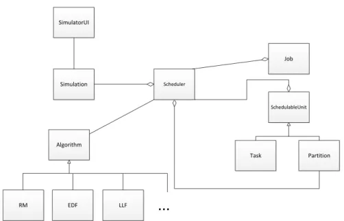
On Figure 3.1 we show the domain model we used to plan the creation of our tool, and which were the basic connections needed to be made in order to structure the tool. A simulation will have a scheduler on the lower level (being this scheduler one of the already implemented algorithms, such as RM, EDF, LLF or any other implemented on the tool), which on top will have either tasks or partitions. To schedule (choose which task or partition will execute next) partitions and tasks we will resort to the algorithm. We also use an abstraction of SchedulableUnit that allows the creation of multiple levels without having to specify on the code if it is a task or a partition. This comes from using an abstraction of Explicit Deadline Periodic (EDP) resource model [25].
SimulatorUI Simulation SchedulableUnit Partition Task Algorithm RM EDF LLF Scheduler Job
...
Figure 3.1: Domain Model
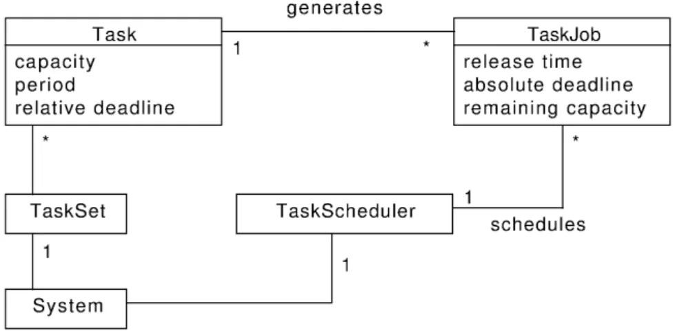
A traditional real-time system is a flat (a one-level hierarchy). The UML diagram for such a system’s domain is pictured in Figure 3.2. The system has a flat task set and a task scheduler. In our tool capacity will represent what previously was called the worst-case execution time (WCET) and the release time is what also was previously named ready time, the time when a job is ready to execute and joins the ready queue and the remaining capacity is how much more time units that job still needs to finish. This diagram shows that is not to hard create a tool to simulate the execution of a simple and flat real-time system.
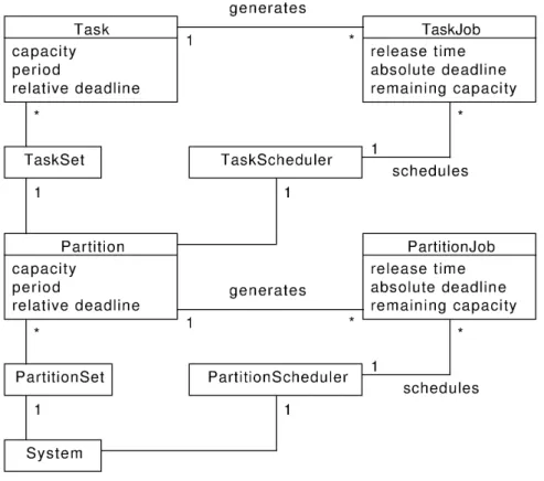
A two-level hierarchical scheduling such as those corresponding to TSP systems can be mod-elled as seen in Figure 3.3. This model its limited to a system which has a root scheduler, on top
Chapter 3. Problem analysis and solution design 15
Figure 3.2: Traditional one-level system domain model
of that is a set of partitions and each partition has a set of tasks. This model its very strict, not flexible to adjust to more complex and flexible systems. The system has a set of partitions and a root scheduler coordinating which partition is active at each moment. Each partition then has a task set of tasks and a local scheduler to schedule the jobs when time is attributed. This model strategy thought adequate to traditional TSP systems exhibits some drawbacks: it is limited to two levels, and it only allows homogeneous levels (i.e., partitions and tasks cannot coexist at the same level).
3.3
Design
The design of this tool, was surrounded by two main ideas. First how to create an undetermined level of partitions by abstracting partitions and tasks, which implications and necessities would come from this idea. Second how should we view the passage of one unit of time, what would it affect and how, which implications would have and how to make the internal tool clock move.
In the future where more and more complex systems should emerge, taking that in considera-tion we envision that in a quite near future systems may require more than two levels of hierarchy to manage their internal operations or sub-systems. The space agencies are now working on con-verting their systems to support Time- and Space- Partitioning in order to try and reduce the costs of space mission. To do so they will require prior verification, validation and simulation of their systems. Since the complexity of these systems is very high a two-level hierarchy may not be sufficient to support this new necessities, therefore we aim for an higher goal, the possibility of creating more than two levels of hierarchy.
Chapter 3. Problem analysis and solution design 16
Figure 3.3: Two-level hierarchical scheduling system domain model
3.3.1
Composite Pattern
The Composite pattern is designed to represent hierarchies of objects, and to allow the clients to ignore the differences between the composition of objects and individual objects [26].
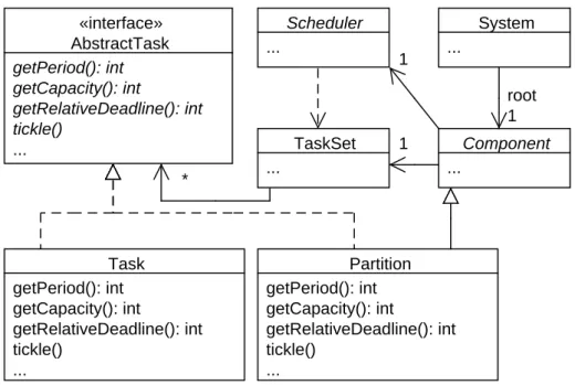
Figure 3.4 shows the representation of the Composite pattern as applied to our domain. Apply-ing this pattern to our model of hierarchical schedulApply-ing allows breakApply-ing the limitation of levels of the hierarchy and the need for the hierarchy to be balanced. The introduction to our system of the interface AbstrackTask, which is a schedulable unit will allow us to represent tasks and partitions, reducing the efforts in reaching a solution. Each time a partition is created, it is see by the system as one more component therefore allowing it to have a scheduler and a task set.
3.3.2
Strategy Pattern
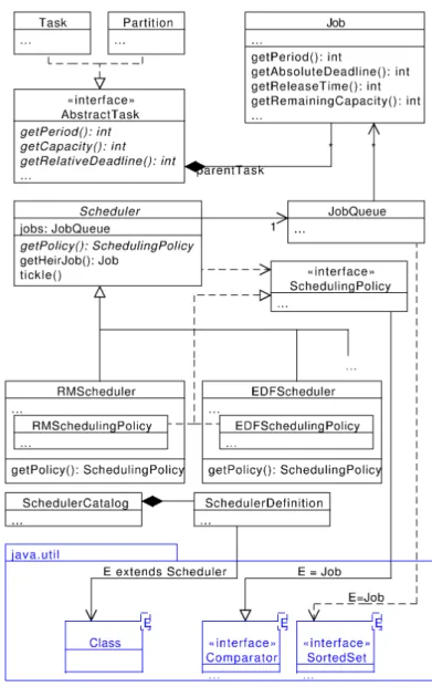
The Strategy pattern is a solution when we want to define a family of algorithms which should be interchangeable from the clients point of view [26]. In designing of hsSim, we apply the strategy pattern to encapsulate the different scheduling algorithms, as seen in Fig. 3.5. The Sched-uler abstract class is the one that obtain the scheduling policy to this concrete execution. The SchedulingPolicy interface extends Java Comparator interface, this way an instance of sub class of SchedulingPolicy can be used to maintain the scheduler’s job queue ordered for the scheduling
Chapter 3. Problem analysis and solution design 17 «interface» AbstractTask getPeriod(): int getCapacity(): int getRelativeDeadline(): int tickle() ... Partition getPeriod(): int getCapacity(): int getRelativeDeadline(): int tickle() ... Task getPeriod(): int getCapacity(): int getRelativeDeadline(): int tickle() ... Scheduler ... TaskSet ... Component ... System ... root 1 1 1 *
Figure 3.4: N-level hierarchical scheduling system using the Composite pattern
algorithm to use it later. Each new Scheduler we implement will require its own scheduling policy in order to properly execute with our domain. The remaining classes shown on the figure 3.5 like Job or AbstractTask or Scheduler are a little more detailed, a few basic methods they will need to provide in order for the system to execute and further detail will be given on the implementation section.
3.3.3
N -level Hierarchy and Polymorphism
Due to the design decisions of using Composite and Strategy patterns, most operations can be implemented without having to worry about which schedulers are present or the size of the hierar-chy. By taking profit of the polymorphism, we can invoke methods on Scheduler and AbstractTask without knowing their subtypes.
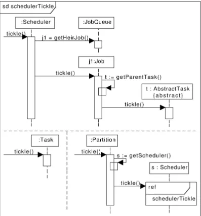
Lets us now see how, the most important operation of the system works. The tickle operation, which simulates the advance of system execution by one time unit. The Figure 3.6 shows the UML sequence diagram of the operation. The hierarchical tickle process is invoked on the root scheduler without regards for what subtype of Scheduler it is. The right job to execute will be obtained because the job queue is maintained accordingly ordered by the instance of SchedulingPolicy. This selected job is then tickled, and tickles its parent AbstractTask without knowing if it is a Task or a Partition.
The behaviour of the AbstractTask is a little different depending on which class it is repre-senting. If it is a Partition instance, this invoke tickle on it own internal scheduler, a unit will be
Chapter 3. Problem analysis and solution design 18
Figure 3.5: Scheduling algorithm encapsulation with Strategy pattern
reach a task. When the tickle arrives to a job that is a result from a Task, same as in the other one time unit will be reduced to the remaining capacity and the difference is that no more scheduler will be tickled and this tickle() operation comes to an end.
It is our objective to decouple the simulation aspects (logging events) from the simulation domain itself. On the one hand, we want changes in the simulated domain (partitions, tasks, jobs) to be externally known of, namely by loggers, without the domain objects making specific assumptions about these loggers behaviour or interfaces. On the other hand, we want to create new loggers without coupling them to the domain objects or having to modify them later. the Observer and Visitor patterns are an appropriate solution to our problem.
Chapter 3. Problem analysis and solution design 19
Figure 3.6: Sequence diagram for the schedule tickle operation
3.3.4
Observer and Visitor Patterns
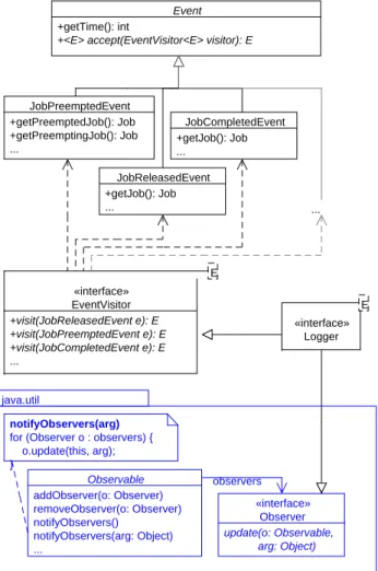
The Observer pattern defines a mechanism where the observers are notified automatically of the state changes of the objects they are watching. The observed objects have only to disseminate their state changes to a vaguely known set of observers, in a way that is totally independent of how many or who the observers are. The Visitor pattern defines a way to represent an operation to be performed on a object hierarchy independently from the latter [26]. Observer pattern guides loggers in choosing from what domain they wish to receive events, and the Visitor pattern helps each logger define what to do with each kind of event.
Our application of these patterns in hsSim is pictured in Figure 3.7. We take advantage from the simple Observer implementation provided by Java, with the Logger interface extending the Observer interface. The Logger class implements the ILogger interface that extends our EventVis-itor interface, which defines methods to process each type of event as well as Observer.
3.4
Summary
This section describes the stages, the objectives and the decisions made to the best of our possi-bilities build an extensive and modular tool. To better understand why we aimed for an n-level
Chapter 3. Problem analysis and solution design 20 E «interface» Logger E «interface» EventVisitor +visit(JobReleasedEvent e): E +visit(JobPreemptedEvent e): E +visit(JobCompletedEvent e): E ... JobCompletedEvent +getJob(): Job ... Event +getTime(): int
+<E> accept(EventVisitor<E> visitor): E
JobReleasedEvent +getJob(): Job ... JobPreemptedEvent +getPreemptedJob(): Job +getPreemptingJob(): Job ... Observable addObserver(o: Observer) removeObserver(o: Observer) notifyObservers() notifyObservers(arg: Object) ... «interface» Observer update(o: Observable, arg: Object) observers notifyObservers(arg)
for (Observer o : observers) { o.update(this, arg); }
java.util
...
Figure 3.7: Logger (Observer and Visitor patterns)
as well as their limitations. It is shown how it is possible to abstract the object to create a mul-tiple number of layers, and how the system should work to ensure the proper propagation of the information through the various levels.
To facilitate the abstraction within the system, and as it was decided to use Java for the devel-opment of the tool, the use of Object Oriented Analysis and Design and Patterns will facilitate the implementation.
We felt necessary to use the Composite pattern, to abstract partitions and tasks, cause in their essence in the system they both will have a capacity associated, so both when time is attributed will have to diminish one to that remaining capacity. The difference and this is where the Composite pattern is most helpful is when the parent task is tickled as well, will be sorted if the job was a task or a partition and if it was a partition then the partition’s internal scheduler will be tickled and the process will be repeated. Using this abstraction we accomplish one of the main goals we set on the beginning of this work, the ability to create multiple levels and apply them Hierarchical Scheduling, although we must assure time and space partition not only between levels as well within the same level.
Chapter 3. Problem analysis and solution design 21
Since another objective of this tool is modularity, the use of Strategy, Observer and Visitor patterns makes it possible and easier. The Strategy pattern facilitates when implementing a new scheduling algorithm to the tool, cause it is separated from the domain of the application. The Observer and Visitor do the logging of status changes on the domain, the observer will catch them and the visitor has a set of methods to be implemented according to the possible status changes that are launched on the domain. Any user that implements a new class that implements the Visitor can create a fully customizable output log, adapted to his own needs.
Chapter 4
Implementation and tests
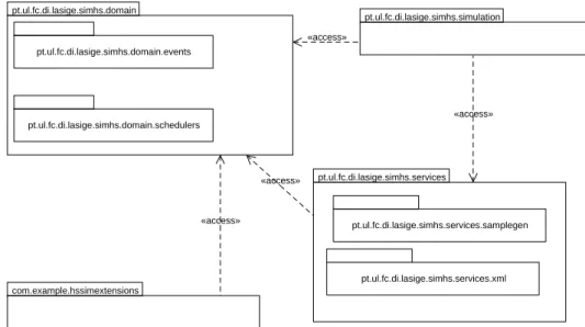
In this chapter we describe how we have implemented the design and ideas described in the pre-vious chapters. The Figure 4.1 shows the organization we saw fit to structure the solution to our tool, more detailed information about each package will be given in the next sections. Will also show some examples of simulations to test the assumptions we have proposed.
«access» pt.ul.fc.di.lasige.simhs.services.samplegen pt.ul.fc.di.lasige.simhs.domain.events pt.ul.fc.di.lasige.simhs.domain pt.ul.fc.di.lasige.simhs.domain.schedulers pt.ul.fc.di.lasige.simhs.services pt.ul.fc.di.lasige.simhs.services.xml pt.ul.fc.di.lasige.simhs.simulation com.example.hssimextensions «access» «access» «access»
Figure 4.1: Packages Diagram
4.1
pt.ul.fc.di.lasige.simhs.domain Package
This is our main package since the whole definition on how the application works is defined in here, as well as all the constructors to every Java class necessary to run a simulation.
In this package the class AbstractTask is an abstract Java class that will be extended by both Task and Partition and regulates the results to expect from them. Here is defined some of that basic methods that need to be implemented such as, tickle(), as well as some already implemented methods to return information about the abstract class.
Chapter 4. Implementation and tests 24
The Clock class that makes the time run so that the application can know that time has passed. This clock is an ”abstraction” of what we call a real clock so it does not count seconds but does count Units of Time, which is what we need on a simulation. This clock starts at time = -1 to automatically create the jobs at time = 0.
The Component interface is used to represent the parent task or partition that represents each Java object. It is this way we can differentiate one the tickle operation if the Partition scheduler needs to be tickled or not.
The EventVisitor interface defines the methods and parameters of all the events that the do-main can be released. The methods implemented on the simulation package will originate the loggers of the tool.
The Job class extends the AbstractTask will generate Java objects that are the result of a new instance of an AbstractTask on a given time of the execution, it will be here that the passage of time will consume the remaining capacity of itself if time is attributed to it.
The JobQueue class implements an Iterable Job and it is responsible to keep this set of jobs in order by a given policy, so when the scheduler call for the heir job it returns the first on this set. The Partition class extends the AbstractTask and has independent TaskSet (a Set of tasks) to be able to launch a job when its release time comes. Also has an internal Scheduler to schedule his own jobs.
The RTSystem class creates the basic objects necessary in a simulation. It also responsible for the lower level scheduler and for tickle the partitions or tasks on top of it.
The RTSystemEvent abstract class defines the basic behaviour of the events launched by the domain, as well as arguments they need to carry, until they are handled.
The Scheduler is an Java abstract class that extends Observable and will regulate which job will be executed first according to the chosen policy. It is also responsible for launching the jobs of its taskset to the jobqueue to execute them, check if they have terminated or even if its deadline has passed. Policies are implemented in the package with the schedulers, totally independent which supports our modularity objective. Here will be launch some events such as, JobCompletedEvent, JobLaunchedEvent,...that will be handled in other package.
The SchedulingPolicy interface extends Comparator that defines how the jobs are organized on the set while waiting to be executed.
The Task class extends the AbstractTask and here is the defined how to create a task and his behaviour through the execution of the simulation.
The TaskSet class structures the actions a task set need to have in order to create a task set. The classes Scheduler and Job launch notifications that will be caught by the Observers (ex-plained further ahead) of the most important actions inside the tool, such as job creations, job execution, job termination, job deadline miss, partition execution, and partition terminate. With this notifications users can create their own Logger classes and represent the events that happened in the simulation as they please (see section 4.3).
Chapter 4. Implementation and tests 25
4.1.1
pt.ul.fc.di.lasige.simhs.domain.events Package
In this subsection we explain the structure of an event. An event is a Java class that extends RTSystemEventwhich on each of the different classes of events possible on their constructor there is a reference to time of the event occurrence. The List of classes in this package are the ones possible to be handled on the simulation extension classes users define.
4.1.2
pt.ul.fc.di.lasige.simhs.domain.schedulers Package
In this package are implemented some basic schedulers that represent their own categories, the fixed task priority scheduling algorithms, the fixed job priority scheduling algorithms, and the dynamic job priority scheduling algorithms. Any of this algorithms, or any new one that users create can be used on simulations.
When extending the scheduler class, any possible algorithm imagined by the users can be implemented. In this package is a catalogue that allows to instance the schedulers by name, to facilitate their instantiation.
4.2
pt.ul.fc.di.lasige.simhs.services Package
The abstract classes IReader and AbsSystemsReader are the basic connection from the services package to the domain package as shown in Figure 4.1, more specifically to the RTSystem class.
4.2.1
pt.ul.fc.di.lasige.simhs.services.xml Package
The XmlReader class that extends AbsSystemsReader is a class that allow users to create their own simulation systems in an XML format. This class will read the XML from the file and construct the system as specified in the file.
4.3
pt.ul.fc.di.lasige.simhs.simulation Package
The AbstractBasicSimulator abstract class structures the basic functions necessary to create a simulation.
The BasicSimulation class is where we create tasks, partitions, schedulers, logger (will be explained in the next paragraph) and define the amount of time we wish to simulate assuming it starts on time equals to zero and moves one by one until the limit defined by the user.
The ILogger interface defined the behaviour of an observer to this application. Our provided Logger prints to the screen some of the most important events such as job launch, job termination and deadline misses. New loggers can be implemented to satisfy user needs, as simple as creating
Chapter 4. Implementation and tests 26
4.4
com.example.hssimextensions Package
To show that anyone can extend the work done by us, in this package we use the GraspLogger class to create the structure necessary to make use of the Grasp Logger application that was not developed by our team. This shows the objective of hsSim to be extensible by third parties that do not need the source code to make this system grow. The use of Grasp was an example that proved the point of extensibility which we since the beginning of this project we aimed for. Any other tool, created by anyone else, could be used to create graphical or textual representations of the results produced by our tool [1].
4.5
Tests
4.5.1
Two-level hierarchy
To illustrate how to create a two-level simulation we will now show an example of a creation of a simulation read from XML and respective format. The use of XML facilitate non programmer users to create simulations since there is no specific programming associated. The XML version of a simulation should look like the following example.
<?xml version=”1.0” encoding=”Windows−1252” ?> <system>
<time time=”20”></time>
<scheduler>RMScheduler</scheduler>
< partition capacity =”2” period=”10” deadline =”10”> <scheduler>RMScheduler</scheduler>
<task capacity =”3” period=”10” deadline =”10”></task> <task capacity =”4” period=”10” deadline =”10”></task> <task capacity =”1” period=”5” deadline =”5”></task> </ partition >
< partition capacity =”2” period=”15” deadline =”15”> <scheduler>RMScheduler</scheduler>
<task capacity =”1” period=”6” deadline =”6”></task> <task capacity =”1” period=”7” deadline =”7”></task> </ partition >
</system> }
To facilitate the understanding of this XML, we built a graphical representation of the system we will simulate. The representation of the previous simulation is shown in Figure 4.2 which represents the schematics of the system we created inside the simulator tool. In this example the RM scheduler below is responsible for the scheduling of its abstract tasks, which in this case are partitions that contain tasks, as they were tasks. This figure represents a two level hierarchy when on the lower level we have a RM scheduler that will be responsible for scheduling two partitions that are on top of it. Each partition have its own inner scheduler as well to schedule their own tasks, which in this case are also RM schedulers. The partition represented on the left is composed
Chapter 4. Implementation and tests 27
by three tasks and the one of the right composed by two tasks.
Here we show an example of a system that is common nowadays (a two level hierarchical system), we now show that our tool delivered the results shown in Figure 4.3 assuring it works according to the specifications held in the XML. This representation format it is not perfect, only an example that allows users to have some representation of the results, where on the left are the tasks and partitions, whenever they get executed the partition time left decreases and a unit of time in a task is used. The arrows represent the release time of each job of that task.
2, 10, 10 2, 15, 15
3, 10, 10 4, 10, 10 1, 5, 5 1, 6, 6 1, 7, 7
RM
RM
RM
Figure 4.2: Two-level system
Figure 4.3: Results of the two-level system
4.5.2
Unbalanced three-level hierarchy
<?xml version=”1.0” encoding=”Windows−1252” ?> <system>
Chapter 4. Implementation and tests 28
<partition id=”partition1” capacity=”50” period=”100” deadline=”100”> <scheduler>EDF</scheduler>
<partition id=”partition1 1” capacity=”30” period=”100” deadline=”100”> <scheduler>EDF</scheduler>
<task id=”task1 1 1” capacity=”10” period=”100” deadline=”100” /> <task id=”task1 1 2” capacity=”20” period=”100” deadline=”100” /> </partition>
<partition id=”partition1 2” capacity=”40” period=”200” deadline=”200”> <scheduler>EDF</scheduler>
<task id=”task1 2 1” capacity=”25” period=”200” deadline=”200” /> <task id=”task1 2 2” capacity=”15” period=”200” deadline=”200” /> </partition>
</partition>
<partition id=”partition2” capacity=”40” period=”100” deadline=”100”> <scheduler>EDF</scheduler>
<task id=”task2 1” capacity=”20” period=”100” deadline=”100” /> <task id=”task2 2” capacity=”40” period=”200” deadline=”200” /> </partition>
<task id=”task1” capacity=”10” period=”100” deadline=”100” /> </system> 20, 100, 100 10, 100, 100 25, 200, 200 15, 200, 200 20, 100, 100 40, 200, 200 10, 100, 100 50, 100, 100 30, 100, 100 40, 200, 200 40, 100, 100 EDF EDF EDF EDF
EDF
Figure 4.4: Three-level system
Figure 4.4 shows the idea that we had since the beginning, the possibility of creating a sim-ulation of systems that were not limited to a maximum of two levels (the systems we encounter nowadays) but allow the expansion of those systems in order to be able to simulate more complex systems. The system represented on this figure shows that in this tool it is not required that on the
Chapter 4. Implementation and tests 29
same level are the exact same type of objects in order to execute simulations. This example shows and two level hierarchy, similar to the one showed on the previous example, as well as, a partition and a task on the level one of this simulation example, showing the benefits of using this tool, in comparison with others.
As we did for the two-level system, shown in Figure 4.2 we did use the Grasp tool in order to show the results of the simulation, said results are displayed in the Figure 4.5.
Figure 4.5: Results of the three-level unbalanced system
4.6
Summary
This chapter described how we structured out packages and what is achieved and where. The domain package have all the classes that are needed to construct a simulation system. The events package have all the events that can be launched by the domain. The services package allow users to create their simulations using the XML format. Finally the simulation package where our logger is achieved and is an example of what the “com.example.hssimextensions” package represents. One of the goals we had when we started this project was flexibility to easily extend this tool, which is this case as an example is done with Grasp.
Later in this chapter we show two simulations using the XML format and respective Grasp output. The first simulation assures that we can simulate systems that are now working to test our tool, systems complex but with room for improvement. That is why we envisioned the creation of more than two levels, and the second example shows that, shows an example of a three level system that is unbalanced. So any new users can just redefine the XML simulation and use the
Chapter 5
Conclusion
We have described the design and development of the hsSim, an n-level hierarchical scheduling simulator. We emphasized the object-oriented analysis and design decisions, such as carefully applying design patterns, through which we pursued the purpose of yielding an open, reusable, extensible and interoperable tool.
Applying the Composite and Strategy patterns allows implementing system operations in-dependently from, respectively, the hierarchy’s structure and size and the underlying scheduling algorithms, furthermore, the application of the Observer and Visitor patterns allow great flexibility to add new simulation loggers, since the simulation and logging aspects are decoupled from the domain concepts.
At this precise moment we were able to build most of what we expected when we start this project. We are able to use any scheduling algorithm existent plus any someone should invent in the future. We can assure separation between partitions, assure only one branch of the tree can execute at each unit of time, never more cause so far it is only focused for one CPU core. We created separation between domain and the logging/observer which allow an easy way to create new logger classes that users see fit.
This tool may help on the construction of systems on the verification phase. To see what can be accomplished using our tool, we will release it under an open source license one Google Code (http://code.google.com/p/hssim/).
Since this project has about just nine months, is safe to assume, we could not address and create a totally complete tool, but we managed to create a good starting point for what could be a great tool on real-time scheduling analysis for academic research. The future of this tool passes by adapting the existing work to several cores since most of the design decisions had that in mind it should not be to hard. The introduction of compositional analysis to assure that we never violate the Time- and Space- Partition properties.