A CONSTRAINT-BASED MODEL TO SUPPORT ELECTRONIC TV NETWORK DESIGN
GERSON FLAVIO MENDES DE LIMA
By
Gerson Flavio Mendes de Lima
Submitted in accordance with the requirements for the degree of Master of Science
Federal University of Uberlandia Faculty of Electrical Engineering
2008
By
Gerson Flavio Mendes de Lima
Submitted in accordance with the requirements for the degree of Master of Science
__________________________________ Edgard Lamounier Júnior, PhD
Dados Internacionais de Catalogação na Publicação (CIP)
L732c Lima, Gerson Flávio Mendes de, 1969-
A constraint-based model to support electronic TV network design /
Gerson Flávio Mendes de Lima. - 2008.
118 f. : il.
Orientador: Edgard Afonso Lamounier Jr.
Dissertação (mestrado) – Universidade Federal de Uberlândia Progra-
ma de Pós-Graduação em Engenharia Elétrica. Inclui bibliografia.
1. Televisão - Teses. 2. Engenharia auxiliada por computador - Teses. I. Lamounier Júnior, Edgard, 1964- II. Universidade Federal de Uberlân-dia. Programa de Pós-Graduação em Engenharia Elétrica. III. Título.
CDU: 621.397
PÓS GRADUAÇÃO EM ENGENHARIA ELÉTRICA
A CONSTRAINT-BASED MODEL TO SUPORT ELECTRONIC TV NETWORK DESIGN
Dissertação apresentada ao Curso de Pós Graduação em Engenharia Elétrica da Universidade Federal de Uberlândia, perante a Banca de examinadores abaixo, como exigência parcial para a obtenção do título de Mestre em Ciências.
Edgard Lamounier Júnior, PhD (UFU) – Orientador Alexandre Cardoso, Dr (UFU) – Co-Orientador Decio Bispo, Dr (UFU)
Arquimedes Lopes Silva, Dr (CEFET-GO)
Área de Concentração: Computação Gráfica / Modelo Baseado em Restrições
physics concepts and computer techniques joint trough mathematical equations and geometrics concepts, to represent real effects. Even though, the two fields have significant different concepts. This research has as objective to propose one approach constraint-based data model, to support an interactive design interface. In order to provide faster and future improvements of Innovation and evolution network in time and frequency domain (Model).
In Special thanks To
My mother; Terezinha My father (in memoriam):
Prof. Dr. Gerson Mendes de Lima Junior To my Wife, Janaina
words to push me forward, he told-me: “Gerson, your evolution is some think that’s not a compromise between you and any other. This is an agreement with you and yourself, just”! No more one can charge for this decision, them you, or your own mind! This friend was not just a colleague, but much more than, he is my supervisor and Mentor, Prof. Edgard Afonso Lamounier Junior. His support and simplest helpfully act front any of my fears, turned the place, were I could find a little bit of my self acknowledge and the motivation to always go ahead and finish this work. I would like to specially thanks to my friend, Ignacio Angel Ocampo, the main Engineer from Argentina’s Country, that gave-me an opportunity to learn all that I know about CABLE TV and introduce this technology and practices in Brazil specially Minas Gerais, working and providing Design and Engineering Services, CAD and Digital Maps, for: CABO TOTAL Company. In the same grade, my Special Thanks to Engineer: David Pedro Junior, to be my Tutor since my under graduation in Electrical Engineer academics practices life, until the present always advice-me using a special respect and stay present in many hard moadvice-ments of my life and Works. My specially thankful, for all contribution of Federal University of Uberlandia; Prof. Dr. Alexandre Cardoso, and his contagious happiness; to Prof. Adelio Jose de Moraes for high level professional deference, in similarity to Prof. Dr. Jose Carlos de Oliveira followed for nobody less important and a Really Technology “Lover” Prof. Dr. Alcimar. My respects to Prof. Dr. Arquimedes Lopes Silva, first to allowed me to use his work referenced, and always strongly synergy, spontaneous actions to help-me with his simplicity and great experience, adding value to my work. To My Dad (“In Memoriam”) for my younger stimulation to search and learn new acknowledgements in many challenges of life, and always continue to looking for improve skills for innovations until achieving highest priorities. Specially grateful to my Mother and her “infinity energy” always ready to protect and give trust in myself efforts, against the obstacles, and never desist!
1. Lima, Gerson F.M. , Lamounier,E., Creating FDO ( Feature Data Objects) and Oracle Structure for Enterprise Telecom Solutions ( Constraint-based Design) application, 15th Annual Autodesk University –on - Civil Engineering and Geospatial - GS32-1L The Venetian Resort Hotel Las Vegas, U.S.A. November 27 – 30, 2006 .
2. Lima, Gerson.F.M., Automação de Projetos Eletricos – Software para Desenho e Dimensionamento de Instalações, IV- Encontro Nacional de Instalações Eletricas, Eletricidade Moderna, Aranda Editora, pp. Colectânea dos Trabalhos Apresentados - Vol I, Sala Amarela, Outubro 1995, ISSN 0100-2104, São Paulo – SP.
1.1 Motivation ... 1
1.2 Objective and Research Goals ... 1
1.3 - Electronic TV Network Design ... 2
1.4- Hybrid Fiber Coaxial Networks - HFC... 6
1.5 Electronic Network Design Workflow ... 9
1.5.1-Costumer Requests (Network Design Requirements) ... 10
1.5.2 - Conceptual Draft ... 11
1.5.3 - Embodiment Design ... 12
1.5.4 - Design Detail ... 12
1.6 - Electronic Design Constraints ... 13
1.7 Thesis Organization ... 13
Chapter 2 Carriers Network Technology & Architecture Outlook... 15
2.1 Introduction ... 15
2.2 – Mulplexing and Multi Access Technology ... 21
2.3- Network Design Sequence ... 31
2.4-Summary ... 36
Chapter 3 Electronic Network Technology Based on Constraints...37
3.1 Introduction ... 37
3.2- Geometric Constraint Representation ... 37
3.3-Electrical Constraints based Representation (permanent state) ... 38
3.4-Electronic Constraint Representation ... 39
3.5-Quality Signal Parameters to Constraints Data Model ... 40
3.6- Related Constraints with this Research ... 42
3.7-Summary ... 42
Chapter 4 Constraint Modeling for Signal Modulation and Electronic Components .. 44
4.1- Introduction ... 44
5.1- Introduction ... 57
5.2-Constraint Engine Modules Architecture... 57
5.3 – The Representation of Constraint Equations and Variables ... 58
5.4 – Building the Geometric Graph Process ... 59
5.5 – The Graphical User Interface (GUI) ... 60
5.6 – Database Fundamentals – Symbol tables, Transactions (AutoCAD – API) ... 61
5.7 –Software Work Process and Interactions GUI – Constraint Manager63 5.8 –Summary ... 65
Chapter 6 Results and Discussions ... 66
6.1 – introduction ... 66
6.2 –Main Features of Implementation ... 66
6.3 – The incremental Process for Electronic TV Network Design ... 68
6.3 – Summary ... 83
Chapter 7 Conclusion and Future Works...76
7.1 – Introduction ... 85
7.2 – Conclusions ... 85
7.3 – Future Works ... 86
Appendix A1-Transmission Lines (TL) ... 100
A2 -Timing Constraints ... 105
A3- Laplace Transformation Model ... 106
A4-Inverse Laplacian Transformation ... 107
A5-Tranformation of Derivates Function ... 107
Introduction
__________________________________________________________________________
1.1 Motivation
Effectively, ability to create a better solution for Engineering Design Process, is a key skill that a professional needs to work well, in conjunction with software tools, provided by an easy to adopt conditions to maintain the technical focus and execute the priorities that match the greatest value of the engineering process. However, these tools must improve the work schedule; it should contribute for what it does in designer mind vision. Providing, inspiration and engagement to permit the creation thinking in innovations solutions that really matter, for improving value to design, and not just features for user interface (UI). It is critical to concept a support decision tool by engineers, which simplifies methods that have proof concept value. Expand the CAD/CAE usage over the largest industry of telecommunication, like the Broadband Television Systems to support a real convergence, common called of Multiservice or multimedia, based in Mesh or coupled Networks is a challenge. The purpose of this work is to develop a concept methodology based on use a constraint-based model, [51,58], adding a contribution value for Electronic Networks TV Broadband Design, establishing, a new model database topology for HFC (Hybrid Fiber-Coaxial), and CATV coupled networks, looking for the highest efficacy of integration, and operation possibility, in real time applications and large solutions [13]. Considering to increase the Software classification to an Engineer System, placing in to highlight the constrained-based space for Electronic TV Engineer area.
1.2 Objective and Research Goals
constraints to support electronic network HFC topology, using its interactive parameters, in the frequency/time domain. Besides, it aims to bring to reality the possibility to explore (simulate) different scenarios, emerged in a constrained-based virtual space, that has contemplate physical relevant parameters, but also allow simulation cases during design time (interactivity). To accomplish this goal it is important to satisfy the equations and geometrics constraints emerged from a based model in Signal Modulation frequency or/and time domain. Finally, it is proposed to develop a software application CAD/CAE using constraint based design schematics for buildings backbones. The goals to advice such objectives are:
z To perform an Introduction Outlook of the actual reality of
Telecommunications Cable Electronic TV and Broadband latest technology used in World (CTIA 2007/2008) and highly level for visualization, organization to useful approaches grouping objects symbols recognition, and depth perception visualization engineer design.
z To propose a data model released in accordance to classical
classifying methods for constraint-based approaches, using the development of incremental graph-based techniques for satisfying a coupled set of electronic engineering and geometric constraints network.
z To demonstrate results based on constraint-based design [51],
application for an Electronic mesh CATV network.
z To Analyze these algorithms and implement a prototype-based system
in Object Oriented Language (Visual C++) including the use for a Software Engineering design process, documentation to fit this work in formal Computer Science Language, and looking to future evolutions.
1.3 - Electronic TV Network Design
some RF diffusion to promote the view of this valued moving images. The popularity was growing over the time, when the nickname: “CATV” – Cable Television, or Cable TV. Emerged, several companies [3], including state broadcaster, started rebroadcast the UK's (then) three terrestrial TV channels in some cities and larger towns. Early cable television operated in an unregulated gray market, [4] with providers laying cables wherever possible from their signal collection point, often the local electrical store. The system was eventually regulate by the Wireless Telegraphy (Wired Broadcast Relay License) Regulations of 1974 in to an exclusive franchise system, where one company holds a franchise to provider analogue cable television and radio services to a specific area. Franchisers under this system referred to as having "1974 licenses".
Effectively CATV systems, those owned commercially, in general began adding services in the early 1980s as English - language services started to appear on satellite, and with most new houses cabled from construction by the late 1980s [5]. It has become the most common multi-channel television reception system, beating satellite television and long-distance UHF reception of foreign channels in to second and third places.
Beyond premium services, set top boxes are, only provided if the customer’s television is unable. To handle VHF signals, as some imported from the UK (which has no VHF television and generally encrypted cable television may). There is no set frequency plan, and the one cable firm may use a mix of European and Irish channel alignments. The physical networks are usually, for analogue standard coaxial cables boosted and tapped at regular intervals, which can lead to serious signal degradation problems, particularly on overhead networks. Digital networks have far more sophisticated trucking systems [6], [7].
modernization has seen the eventual construction of a backbone network linking main nodes [10].
Overhead cables are common in areas constructed before the foundation of the local cable firm, or where the cable firm did not have a construction agreement with builder companies; Underground cables are more common in developments build post-1985 [9],[11].
Early, cable television has operated in an unregulated gray market, with providers laying cables wherever possible from their signal collection points, often the local electrical store. The system was eventually regulated by the Wireless and (Wired Broadcast Relay License), Network Regulations where one company holds a franchise to provider analogue and recently cable television and radio services to a specific area [12]. Franchisers under this system are referred to as having "1974 licenses”.
revolution expects to influence every facet of American life, be it work or leisure [38].
Companies in all industries are using information technology to re-engineer themselves and to become globally competitive. Businesses are gearing up to be a part of today's global information economy and tomorrow's world knowledge economy. In fact, many of the cable issues in question date back several decades [13]. After the cable companies spent many years and billions of dollars setting up their services, the FCC has begun pushing for the implementation of digital cable-ready TVs that would do away with the industry's traditional use of set-top boxes - a move that could make it harder for the cable companies to continue to innovate [16]. The result is a battle between those who favor protections for the original cable companies and those who believe new competitors should be assisting, in the name of increased competition and better customer service.
According to [24]: "The Internet is different from the other communication technologies that have caused great social upheaval: telegraph and telephone, radio and television. The telephone company offers a variety of telephone-related services to its customers - The essential difference is that the telephone company defines telephone service and the network defines the TV content. In contrast, the NII would be participative in nature - where "every client is a server." It treats its users not as consumers of a product or service, but as contributions, as colleagues.
One interpretation of the NII as a "convergence of technologies and of cultures" depicts it as an "electronic market" and an "electronic town hall" [32]: "The National Information Infrastructure ("NII") - today represented by the universally accessible telephone system, broadcast and cable television, libraries, bookstores, remotely accessible databases, and the Internet, and ultimately supplemented by broadband switched networks with digital connections to homes and public facilities -- can be an electronic market for information, and an electronic town hall."
and communications in the US today. Poor households are already spending too much on basic communication services, such as long-distance phone calls. Choosing fiber optics as the primary technology for building the superhighway will be very expensive, for both middle and lower classes. The poor may be already taking in more bandwidth than the rich may, but it is in the form of low-grade information via television, rather than the high-grade information available on Internet (Huber, 1994) [14].
The concept of universal access is ill defined for operative at the grass-roots level. For instance, the primary problem is not if there are enough computers to go around, but what they are used for (Hancock et al., 1995) [11].
Second, George Heilmeier president of Bellcore (1996), this trade-off is likely to be complicated by the need for simultaneous competition and cooperation among the many firms that will invest in the NII..." [31]. The future of electronic communication in the spheres of education, business, industry and government will hardly be same as that in the past.
1.4- Hybrid Fiber Coaxial Networks - HFC
The residential Cable TV broadband service, represent one of the major interest areas for actual telecommunications market and will continue grows for the next years. The advents of interactive services, telephony (VoIp), Internet, Games on Line, Pay per View, increase and incentive for more broadband capacities and Quality of Services.
The large demand for speed, request for better quality of service in distribution signal, since analogical TV, to interactive digital contents providing services to new subscribers possibility;
And The bi-directional signal can be a two-way (full duplex) communication and multimedia turn the reality of Hybrid concept more efficient to interactive networks and expansible these architectures for Telecommunications services has been adopted to dada transmission ( High Speed Internet, home shopping, home-backing, video conferencing, home-working, interactive games), VoD (Video on Demand) and Telephony.
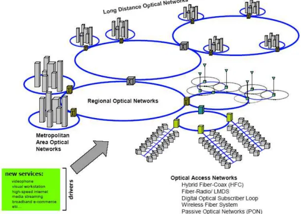
better infrastructure to possibility provide a backhaul for the uncountable number of Station Radio Base for Cellular (Erbs) or also called BSC’s (Base Service Connections). In Figure1.1, the length limits is a barrier to make services upgrades in TV Networks, so it’s necessary to mix newer long distance capabilities to allow the transmission in faster and longest scales, and in the same time have possibility to increase the taxes telecommunication rates without lose quality and have a lowest costs for these upgrade specification.
Head-end
System Troncal 20 a 35 amplifications
10-20 km (max)
Figure1.1 - Traditional Tree and Branch
Head-end
6 a 50Km 1310/1550 nm
Opto-Electronic Converter Opto-Amplifier
HFC - Network
Optical Cable
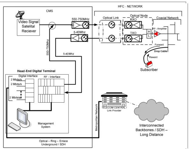
Figure 1.2 - Hybrid Coaxial Fiber Optic Network
As voice over Internet protocol (VoIp) and competition from cable operators continues to erode the telephony market, Telecommunication has increasingly forced to build service portfolios outside their traditional sphere of interest. At the same time, core network developments have opened the door to a new world of triple play, offering consumer broadband, telephony, and television services in a single package. We know IPTV is something consumers value and will pay for—in territories in which IPTV services have been deployed, we have seen promising take-up. When you hear stories like that, it is easy to see why IPTV is regard as one of our highest growth segments and why there is not a single tier-1 Telco in the world that does not at least have a strategy for IPTV. [http://www.iec.org/newsletter/ april07_1/broadband_1.html- April 2007]
The introduction of asynchronous digital subscriber line 2 (ADSL2), coupled with significant improvements in encoding such as Moving Pictures Experts Group (MPEG-4), advanced video coding (AVC), and virtual channel 1 (VC-1), is making it easier to deliver broadcast-quality content to the home. However, just because you can deliver content via broadband does not mean the consumer will want to watch it. Well-established cable firms already offer triple-play services to their customers, and satellite broadcasters have moved into the broadband and telephony arena. If IPTV is to progress, it must offer the consumer something that differentiates it from its commercial rivals.
allowed Mine TV to gain a foothold in a cable-dominated market.
Convenience and content availability are the keys to any IPTV and VoD offering. A decade from now we will probably look back in amazement at a time when we rushed home to meet the scheduled start time of a television program. These networks interconnected for optical analogical rings to provide signal transport between hubs, separated for 20 to 50 Km. Hubs for secondary distribution interconnected for these digital optical rings in metropolitan areas using transmission SDH / SONET- interconnected with others public telecommunications infrastructures existents (corporate networks, telephony rings based in SDH, etc). Each one of these hubs cover a determinate region that use the HFC access networks technology, were many nodes cover the average amount of 500HP to 2000HP. The Network web servers, video servers, and data servers, still distributed in different parts to provide capability to the services demand requests for other sections remotes of HFC. This transference of information is base for the transport optical rings. For this integration is essential to use a very good management system to be possible control and supervise this complex network.
Thus, a constraint-based system compilation has been developed to preview the feasibility of these incremental graph algorithms. It must turn possible to help methodology usage, for integrating many different interfaces and protocols in one common and simplified data structure contents, using the key real requirements to provide, for technical people, the information necessary to make a well interconnection between different origin and convergence.
1.5 Electronic Network Design Workflow
dramatically, enforced by explosive growth of Internet, and progressively the connectivity with mobile technologies and fixed-mobile convergence has led to complex meshed network configurations.
Considering that, most of the Electronic Network Design workflow contemplates symbolic recognition, thematic colors (Lines, Areas, and Network Elements), formulation and many engineering concepts, and for this study proposes, it is considered satisfactions of constraints including management areas. Second Phal and Beitz and Thornton.
The design work can be classified for the following steps Figure 1.3:
Figure 1.3 - Workflow Steps
1.5.1-Costumer Requests (Network Design Requirements)
architecture, including HFC used for Internet, Telephony and Digital Video.
Figure 1.4 – General Outlook Network Architecture
A planning tool is one good way to start the consideration of costs, marketability, performance, assembly, maintenance. Some constraints considerations modeled in Mathematics equations enhance the capability to interaction with these concepts at any Design phase if the design changes the requisites, in order preventing and detecting errors at advanced time line of design workflow.
1.5.2 - Conceptual Draft
will be connected in further simplifications just possible as a result of the abstract geometry (Draft) , or incomplete geometric information that is subjected to modifications in other time, is common case.
1.5.3 - Embodiment Design
This is a translation from Draft to Design, where the cognition concepts are materialized until a definitive layout, according to technical and economic criteria. According to Pahl and Beitz , the definitive lay-out must be developed to the point where a clear check of function, durability, production, assembly, operation and cost can be carried out.
1.5.4 - Design Detail
Geometric Constraints and Engineering Constrains specify an Electronic Network Design. The Geometric Constraints relationships are existing relations between two different geometric entities. Engineering Constraints are equations that represent the physics concepts of electronic components (e.g., Amplifier Gain, Cable loses, interferences, noise frequencies filters, etc). Both constraints can be seen as a unique set of equations. [51].
The possibility, for modify some parameters and to propagate it upstream and downstream over an electronic cable network must be consider. These automation is related of algebraic manipulations (Solution of constraint sets) required by the user.
The hybrid constraints concept is the ideal solution as a method to solving the system of equations and geometric constraints. These systems rely on numeric and interactive solve techniques [51]. Graph-based model can decompose the equations into smaller sets in order to achieve a more efficient equation solution work [51].
The concept of constraints hybrid, will allow direct manipulations of under-constrained electronic network parameters. Using the constraint engine algorithms, evolving solution of the constraint set and engineering constraint cycles locally identified and solved. At this part, this research will make, characterization of constraint-based approaches for the Signal modulation and distribution using dynamic Domain considerations.
1.7 Thesis Organization
This work is organized in seven chapters and the introduction, including a brief History of Electronic Cable TV Broadband Networks and their evolution.
Chapter 2 is an Overview about Telecommunications Electronic Network Design technology and the New Generation Network using HFC Concepts; that allow a graph database structure to be implemented using constraint-based graph data model to support the electronic engineer network design.
and geometrical constraints to support Electronic Network incremental satisfaction of engineering constraints investigates the static time model and approaches for a dynamic states, for time and frequency Domain model.
Chapter 4 is a detailed set of algorithm to, over a graph-based topology, using visual grouping of abstracts and effectively using organized in intuitive visual data. The contents are used to study the modulation basics to support geometric and engineer equations satisfaction exploring the degrees of freedom related of uses, and network topologies data base model in constraints-based concepts. For example HFC – Network
Chapter 5- Is the prototype implementation of software using integration with an API for CAD using Visual C++ and object ARX (AutoCAD Runtime Extension) to create since the symbols standards (draft) Classes, Methods, and members to be able for developed the constraint engine for a complete graph structure database. In the same way use, one graph based in standard symbols, and arcs, considering a graphics usage interface based in high quality level interaction and symbols under rules of Geometrical and engineering constraints models.
Chapter 6-This chapter brings the results of implementation. The User Interface presentation in toolbars commands.
Chapter 2
Carriers Network Technology & Architecture Outlook
______________________________________________________________________
2.1 Introduction
Requests for an information highway running to provide services innovations and improve its utilization over the integration between different telecommunication systems, specially the interconnection of the optical and the RF networks, are the key for evolution and innovation. In Figure 2.1 is presented the schematics of a Telecommunication network, detailing the interconnected layout that compose the complete services oriented provided for the customer, including TV signal in analogical and digital mode and internet services.
Considering the referred Telecommunications cases, in our application the Graph Structure and the logical method to consider, coupling to be used efficiently cover all concepts inside the rules, in other words, representing the mathematical abstracts the reality of physical laws considering the field.
A well-designed data structure permits many of complexes operations to perform, by algorithm, using as few resources as possible. Therefore, preview in earlier phase the appropriate choice of data structure is indispensable to start a correct dimensioning of: logical, physical and abstracts mathematical parameters that must represent a Virtual Reality in the network.
This insight must be rise for many formal Electronic Multimedia Network design methods and programming languages, such module system, allowing data structures safely reuse in different applications propositions by hiding their verified implementation details behind controlled interfaces.
The object oriented programming languages, uses their purposes in classes applications development, because it is bring accuracy and performance. Depending on networks is becoming either more mature or more disruptive. The fixed mobile convergence (FMC) will integrate mobile phones with PBX, and enable unified communications, including data compression multiplexing providing broadband signal convergence. In this tip, looks at FMC deployment options and equipment are prerequisites of any enterprise network ready for FMC, [61], [62], [63], and [64].
On the large and infinite scientific way, Graph algorithms are a significant field of interest for computer scientists.
In mathematics and computer science, graph methods is the mathematical structure used to model pair wise relations between real elements and abstracts relations, like Network Elements or objects from a certain collection. A "graph" in this context refers for a collection ‘nodes’ and a collection of edges that connect pairs of vertices. A graph may be undirected, meaning that there is no distinction between the two vertices associated with each edge, or its edges may be directed from one vertex to another; (A Coupled concept) [51].
them. Benjamin Peirce called it "the science that draws necessary conclusions".
Using the graph terminology used in this section, Graphs are generally chosen to represent constraint network because the general domain-independent representation, they allow both qualitative and quantitative operations, and there are a large number of applicable algorithms from the literature.
In Reality; a maturity side technology, IP and Ethernet networking are now well understood and can be intergraded based on use of newer technical changes to the basic infrastructure, has been simplified, since the provider network services. Until the networks deployed with, an emphasis on service delivery performance, optimization and ROI, especially in case of Image frames, interactive video, QoS in higher levels.
Some emphasize the computation of specific results (such as computer graphics), while others relate to properties of computational problems (such as computational complexity theory). Still others focus on the challenges in implementing computations. For example, programming language theory studies approaches to describing computations, while computer programming applies specific programming languages to solve specific computational problems with solutions. A further subfield, human-computer interaction, focuses on the challenges in making programs that really can add value, and not just features, Figure 2.2.
Ethernet can replace existing networks that use ATM switches and SONET multiplexers on an OC-48 SONET ring with a simpler network of 10 Gigabit Ethernet switches and at the same time improve the data rate from 2.5 Gbps to 10 Gbps. The 10 Gigabit Ethernet is expecting to be use for interconnect local area networks (LANs), wide area networks (WANs), and metropolitan area networks (MANs). The 10 Gigabit Ethernet uses the familiar IEEE 802.3 Ethernet media access control (MAC) protocol and its frame format and size. Like Fast Ethernet and Gigabit Ethernet, 10 Gigabit Ethernet uses full-duplex transmission, which makes possible a considerable distance range.
On multimode fiber, 10 Gigabit Ethernet will support distances up to 300 meters; on single mode fiber, it will support distances up to 40 kilometers. Smaller Gigabit Ethernet networks can feed into a 10 Gigabit Ethernet network .The increased focus on wireless and mobility creates a new era of "always on" communications and ushers in a new level of synchronization, specially in TV technical of PCS. (Signal Digital Process) .Along with wireless and mobility, network security is also creating disruption. The theory of a self-defending network, coupled with enterprises' having less control over their own networks, is creating a scenario where "fewer and fewer people are sitting behind this well-maintained perimeter,” [80].
A massive increase in mobile and "anywhere" workers has catapulted the use of VPNs to secure the network, regardless of where end users are entering. This level of network-independent security is going to increase, [81].
Real-time communications, such as unified communications, IMS and fixed mobile convergence, are also introducing interesting challenges, he said. In the near future, IP PBXs and desk phones may go away and be replaced by instant messaging and presence-based software and mobile devices. As these new technologies and considerations continue to evolve, network operations and management issues increase as well.
Figure 2.2 – Common optical ring for metropolitan distribution nodes of average 500 HP
For HFC networks and better understanding a symbols, and electronic equipment representation scales, level is defined the following FCC rules and practices for Engineering Design, Figure 2.2:
TV – Broadband - Carrier Signal Level Units Units of measurement in the cable system
a. dB – expresses ratio of two power levels 1- Gain and loss of signal
2- Not quantity definite dBmv
1- One mV across 75 ohm = 0 dBmv (not zero signal).
2- Signals in dBmv are so many times greater or less than (one) 1, 0 mV.
These parameters are measure in accordance of the modulation level detailed in the frequencies spectrum, Figure 2.3.
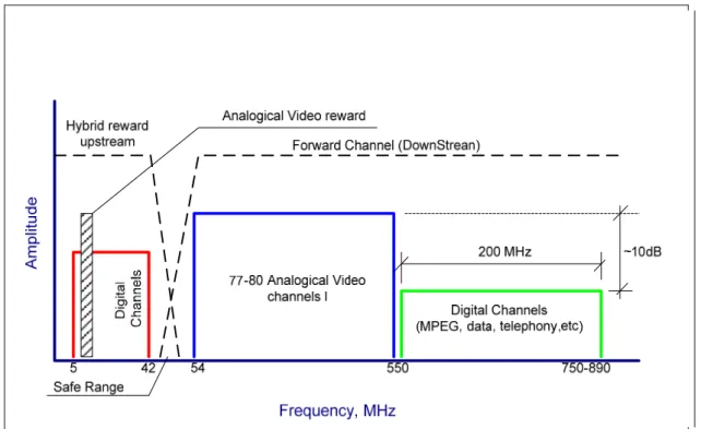
Figure 2.3- Frequency spectrum for Upstream and Downstream link modulation band a) 5 - 42 MHz – High Frequency Spectrum
Return signal for upstream transmission (Internet cable) and interactive commands. b) 54 – 300 MHz - Very High Frequency (VHF)
Ch. 2 – 36 (This consideration range is for analogical digital bandwidth usage). c) 300 MHz - 3 GHz , Ultra High Frequency (UHF)
- 550 systems up to channel 78 – analogical channels - 750 systems up to channel 116 - analogical channels - 1.0 GHz up to channel 180 - analogical channels
(This range is for analogical digital channel bandwidth usage, if the consideration is for Digital Channel it is possible to usage of 10 MHz bandwidth for average 8 to 12 channels per hoop).
2.2 – Mulplexing and Multi Access Technology
The HFC networks are inherited for multi-access use. To allow the Physical means of transmission shared between many users and maintain a quality of service (QoS) provided by network system is necessary to use multiplexing and multi-access techniques. The Standard and efficient mode is the Frequency Division Multiplexing (FDM) in combination with a Time Domain Multiple Access (TDMA), this method share spectral parts for many users in different time ranges. It’s the main factor to guarantee the QoS for the end customer maintenance, Figure 2.4.
Figure 2.4 Multi-access TDMA-FDM
The QPSK – (Quadrature Phase-Shifting Keying) is the most modulation type used to the return channel (reward), motivated for the best relation signal noise. The QAM
(Quadrature Amplitude Modulation) is the modulation used for direct channel (Forward). This class of modulation is also known as M-QAM, for be commonly used in many degrees of ordinations. Although as higher degree ordinations, more complexity the modulation will have, but also higher spectral efficiency. The OFDM
ingress noise of channel (SBT’s 97). This is an orthogonal multiplex method, so with this modulation the sub-channels can be allocate nearest each other, without a possibility of co-channel interferences.
Figure 2.5 - Headend - Digital - CATV and Multimedia Services
Figure 2.6 – Signal processing locations – [ANSI/SCTE 15, 2001]
Figure 2.7 Cable Standard Symbols- (Coaxial) [ANSI/SCTE 15, 2001]
To the Network Active Elements as Amplifier types exist many different types but basic concepts are the same, Figure 2.8.
Figure 2.8– Not Standard – RF Amplifiers – [CMS WG6-0001]
channel signals at higher levels than the low channel so that the input levels at the next amplifier will be closer to flat. The EQ’s are Two basic types : pre stage equalizers are devices which flatten signal levels on the input of amp, if high channel signal levels have dropped below the low channel levels then an EQ is needed. An EQ loses more signals at the low channel than the high, thereby creating a flat slope (or at least close to it). Mid stage, EQ is the same as pre-stage but they are located in a different part of the amp – in between the gain blocks to give the amplifier the desired output slope. Cable simulators opposite of EQ’s, lose more signal on the high channel than the low, for short spaced amplifiers pads are devices, which lose equal amounts across all frequencies, used to knock signal levels down to minimum input level of amp. The Internal couplers are devices for splitting output of amplifier, a plug-in device to create additional lower output legs. The performance noise and distortions increase each time the signal is amplified. Amplifiers do not produce an exact but stronger replica of the input signal in forward and reverse designing a two way system. The Carrier to Noise ratio (C\N) ratio of noise to strength of carrier signal and the Composite Triple Beat (CTB) summation of spurious signals, stack together on each channel to create interference. Composite Second Order (CSO) has similar characteristics as CTB. The Network Passives Equipments are at Figure 2.9.
Splitters – send the signal into several directions Figure 2.10
• 2 way splitters / 3 way splitters
Figure 2.10- Splitters • drop splitters
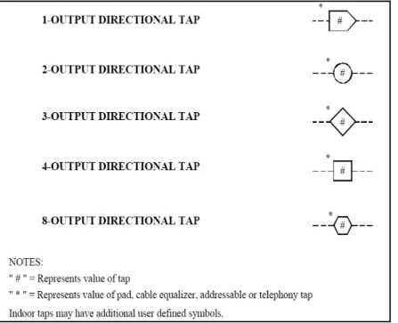
• Taps (Figure 2.9)
• Two, four, and eight way taps – how many subs can they feed.
• Tap values
• Tap losses – insertion loss
• Tap output levels – determined by drop referencing, may be different in different areas of the same system depending on drop distances.
• Splices
• In line EQ’s – function the same as eq’ s in amps except these splice directly into the cable to correct the slope downstream
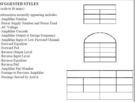
Figure – 2.12 – Data Identification for Design Parameter in Maps
Commscope Catalog – Broadband
Figure 2.16 – Cable Losses per ft and per meter
The Electronic Design Architectures Models (Concepts and Technology) are basically, what type of amplifiers and how they can be used as:
• Cascade – how many actives in line with each other
• Tree and Branch (not used any more)
• HFC – Hybrid Fiber and Cable Network (nodes)
• NGN- (New Generation Networks)
• MDU – Backbones Designs (Multiple Dwelling Unit)
2.3- Network Design Sequence
The chronological work phases for Electronic Network CATV and other analog areas like Utilities, is start using a mapping program. Using Harnessed the power of AutoCAD with specific, easy to adopt routines to draft base, strand, geography, and as-built.
Base Mapping
• Road Draft and Clean Up.
• Define Lot Lines, or Home Passing (HP) Positioning.
• Define Geography features (Georefereciated Information’s) – (Projection System).
• Buildings – MDU (Multiple Dwelling Units)as shown Figure --:
Strand Mapping
• Field Survey to complete information’s on the Map.
• Annotation for each number of HP (home passing) per number or address using their Right Symbol.
• Classify the Home Passing (HP) types (Commercial, Residential, Multiple Dwelling Unit) and Economic Level A,B,C or D.
• For MDU – identify the number or Dwelling Units and number of HP’s each.
• Classify poles for availability to anchorage Coaxial Cable or Optical Cable, without any interference with electrical distribution network, or other telecommunication cable’s provider.
• Mark in the Map, the Head End Position
• Identify the necessary underground future installations and describe it.
Figure 2.18 - Detailed Strand Map –Site Survey Preliminary Study – Uberlandia - MG/Brazil PROENGTELECOM / IMAGETV - 1998
Preliminary Studies (field survey)
• Realize the House Counting, or the evaluation for better position for nodes to attend the amount of customers in determinate area ( Divide the average of 500HP’s per node, looking to further divide this node for small number (e.g. average 125 HP's).
• Classify the places with potential customers, Figure
• Disposition special installation for areas with large amount of MDU’s
provide easy access for maintenance group in case of energy disruption, lights, etc.
• Define the amount of Express RF amplifiers and the quantity of Line Extenders will be better to provide Video, Internet, Telephony, and other interactive services.
Figure-2.19 - Economical and Technical Area for one or more Nodes Definition- PROENGTELECOM / IMAGETV - 1998
-Design the Network
• Trace the express coaxial cable rotes until the Optical None.
• Trace the Optical cable Route to Connect from Headend to each optical node ( Ring, or Tree)
Figure–2.20 - Hybrid Coaxial Fiber Amplifier Adjusts for best performance Network- PROENGTELECOM / IMAGETV - 1998
• Position the Tables of each active equipment for easy understand of the Signal Level and adjustable possibilities.
• Define the Best passive TAP, to possibility the Last Mile Drops Cable connections, using enough exits to attend the demand of usage. (Considering Insertion Loses – Forward and Backward).
• Equalizers positioning to correct “Tilt” problems in all places of network.
• Consider the other Telecommunication Pops (Points of Presence) location and preview expandability for network interconnections.
• Dimension the amount of the MDU’s and preview its demand for the main design.
MDU Backbone Network Design (sub circuits of CATV Network)
Figure -2.3.5- Legend Specs Detail Standard format - A3 (PROENGTELECOM)
• Is Necessary to consider a detailed field survey to turn possible to identify problems in early phases.
• At figure – is shown the Internal Amplifier (MDU) and it’s adjusts based in the Forward and Reward Level necessary to attend the internal users and the overall network. These parameters are always mentioned in dBmv for low channels and higher channels.
• At the same figure is detailed the level for etiquettes for Analyze the Signal Levels at any connection or interest points.
Network Reference Model and Standards
carrier network segments: metro collector/access ring, metro core/IOF rings, and core IP/SONET network with their associate standard protocols.
2.4-Summary
Electronic Network Technology Based on Constraints
___________________________________________________________________
3.1 Introduction
The propose of this dissertation is to make a contribution for a new model database, using interactive capabilities with design information, to represent network electronic elements represented by constraints formulated concepts. The idea is to use this database prototype facility to allow the designer to test a conceptual HFC proposes and transactions, preserving consistency and update trustable [73], including the high frequency spectrum represent physical phenomena’s in time domain and / or frequency domain.
The data model, should define integrity constraints based modules agents to leading the geometric and engineer equations satisfaction based and using an interactive algorithm over the proposed design [75].
3.2- Geometric Constraint Representation
The geometric parameters involved in the electronic design in practice are directly dependent of the spatial disposition of each electronic component representation inside the circuit, specially for capacitance and inductance. The Constraint approach is an efficient concept to allow the user to interact with the circuit design model imposing an incremental and verification loop to concept the circuit model and simulation [57], [58]. Graph algorithms are a significant field of interest used to represent and to solve constraints [51]. Typical operations associate graphs methods procedures and non Linear Constraints, specially engineering networks, with their selected output variables. For this research it is used the incremental equation solver that has been improved by many scientific works, referred as INCES, and allow to use nonlinear constrains to be processed symbolically as carrier to noise figure, handled according to their constraint states [58]. The related works using
that is under or over constrained (layers). The special usage of this way is the necessity to implement nonlinear equations and permit its insertion incrementally and at the same capability to simplify engineering constraint cycles into small parts of the equation graph, which is visited due the constraint insertion process.
The Electronic Network data base model must represent engineering constraints as equations within the equation graph. Basic symbols represent geometric entities [51]. Constraints are specified through other objects, so that one object may depend upon another. In this situation, the system reacts to a change in one object's parameters by adjusting the constraints of any dependent objects.
The constraints remain satisfied, but the user is free to decide how is the best solution. This provides an easy-to-use interactive interface, with immediate feedback and control. This research turns easy model data preparation for visualization attributes, and integration with the workflow process in Engineer Design, particularity to MDU design.
3.3-Electrical Constraints based Representation (permanent state)
Lopes and Lamounier [57] presented a graph representation for electric circuits as shown in Figure 3.1.
Figure 3.1 – Electrical circuit representation
Node – N3: IR1 – IR2 = 0 (3.2)
Node – N6: IR2 – Ivs = 0 (3.3)
Using the matrix of incidence, result: V = A’ x E
Figure 3.2 – Tension for each node and branch current
Simplifying the above equations, the node Vector (Tension) is present by:
E= ( A x Y x A’)¹ x (Y x Vs - Is ) (3.4)
Using this concept, we can determine the Tension for each Node and branch current. Figure 3.2. The challenge duties for this research, is establish a similar constraint model equivalence concept for an electronic elements, specially capacitance, inductance, amplification, splice, and equalizer, under the Time and Frequency Domain. The methodology to implement digital services over an existent HFC network is a fundament to all electric circuit that receive energy of a external power supply to its operation, and presents non linear characteristics exhibiting saturation because the physical limitation of the external power supply. In the cable systems the main non linear distortion are the Composite Second Order (CSO) and the Composite Triple Beat (CTB) [61].
3.4-Electronic Constraint Representation
networks has been an intensive research area in the past decade, due to the increasing signal integrity effects and interconnects dominant delays in designs [13]. In electronics, a signal is an electric current or electromagnetic field used to convey data from one place to another. The simplest form of signal is a direct current (DC) that is switched on and off. This is the principle by which the early telegraph worked. More complex signals consist of an alternating-current (AC) or electromagnetic carrier that contains one or more data streams. Data is superimposed on a carrier current or wave by means of a process called modulation. Signal modulation can be done in either of two main ways: analog and digital. In recent years, digital modulation has been getting more common, while analog modulation methods have been used less and less. There are still plenty of analog signals around, however, and they will probably never become totally extinct. Except for DC signals such as telegraph and baseband, all signal carriers have a definable frequency or frequencies. Signals also have a property called wavelength, which is inversely proportional to the frequency. In some information technology a context, a signal is simply "that which is sent or received," thus including both the carrier and the data together. In telephony and TV a signal is special data that is used to set up or control communication.
3.5-Quality Signal Parameters to Constraints Data Model
In communications, the carrier-to-noise ratio, often written CNR (Carrier to Noise Ratio) or C/N (Carrier to Noise), is a measure of the received carrier strength relative to the strength of the received noise. High C/N ratios provide better quality of reception, and generally higher communications accuracy and reliability, than low C/N ratios.
C/N = 10 log10 (Pc/Pn) (3.1)
Where:
is a measure of signal strength relative to background noise. The ratio is usually measured in decibels (dB).
If the incoming signal strength in microvolts is Vs, and the noise level, also in microvolts is Vn, then the signal-to-noise ratio, S/N, in decibels is given by the formula:
S/N = 20 log10(Vs/Vn) (3.2)
If Vs = Vn, then S/N = 0. In this situation, the signal borders are unreadable, because the noise level severely competes with it. In digital communications, this will probably cause a reduction in data speed because of frequent errors that require the source (transmitting) computer or terminal to resend some packets of data. Traditionally, this has been done by using the narrowest possible receiving-system bandwidth consistent with the data speed desired [61]. However, there are other methods. In some cases, spread spectrum techniques can improve system performance. The S/N ratio can be increased by providing the source with a higher level of signal output power, if necessary. In some high-level systems such as radio telescopes, internal noise is minimized by lowering the temperature of the receiving circuit to near absolute zero (-273 degrees Celsius or -459 degrees Fahrenheit). In wireless systems, it is always important to optimize the performance of the transmitting and receiving antennas.
3.6- Related Constraints with this Research
It is usual to see that a number of common interfaces are implemented in the same area in high- speed designs. Each interface has its own specification on the relative timing requirements for signals within that interface (like differential pairs). It is desirable, to have the I/O cells belonging, to the same interface, physically close to each other (or even in a preferred order), which reduces the delay and SI variations, between signals of the same interface. In particular, differential signal pairs are usually required to escape and to be routed together on the package.
This imposes not only a closeness constraint but also bump assignment feasibility constraints (e.g., bumps escaped on the same layers). It is decisive, for the attainable quality models, for verification of the network circuit behavior. The device models are use to represent some function in the nodes or arcs. The requirements for a good model in a circuit simulation environment are quite stringent. The models must be accurate, because they limit the attainable simulation accuracy. Additional model, restrictions may be posed by simulation algorithms, such as the Newton Raphson [57], [58], algorithm and the time integration scheme: good models are at least continuous as a function monotonic in the device behavior. Usually, the continuity of the first partial derivate is also required, causing (Graphic Simplification) smoothness. For performance targets, Federal Communications Commission regulations require that the analog NTSC TV channel CNR in U.S. cable systems be no less than 43 dB at the subscriber terminal. Good engineering practice suggests that the worst-case CNR should be better than the FCC minimum-most modern cable networks are designed to provide end-of-line CNR in the mid to upper 40s. The assumed channel transmission characteristics in the DOCSIS Radio Frequency Interface Specification include the following minimum CNRs for digitally modulated carriers, regardless of modulation format:
Downstream: 35 dB / Upstream: 25 dB
3.7-Summary
parameters, and cause the increased model and modeling.
A list of net constraints and a list of complete path constraints are fed to the sub-graph generator during operation. A refined sub-sub-graph is output, to the net constraint generator:
a) Transforming the differential equation in a circuit based in one algebraic equation (Carrier to Noise Figure) presented in Chapter 4, Figure 4.3 and Figure 4.4.
b) Satisfy the equation for one single algebraic incognita.
Chapter 4
Constraint Modeling for Signal Modulation and Electronic
Components
________________________________________________________________________
4.1- Introduction
The (Orthogonal Frequency Division Multiplexing) is one modulation technique used to minimize the noise channel ingress. It uses dynamic bit allocation per channel. Basically, the spectral allocation is subdivided in sub-channel groups in identical bands, each one using its own sub carrier. In contrast to the modulation frequency division (Frequency Division Multiplexing-FDM), the technique OFDM number of bits per channel depends on the noise level in operation carrier. It means that in the signal region signal of more possibility for noise and attenuation, the bits number per channel can be low. In some cases, the channel can be completely mapped.
Kbit/s (DSOs) of bandwidth inside the 6MHz spectral [102], as shown in Figure 4.1. The OFDM at least provide the double capacity, and could have 240 DS-0s inside 6 MHz [104].
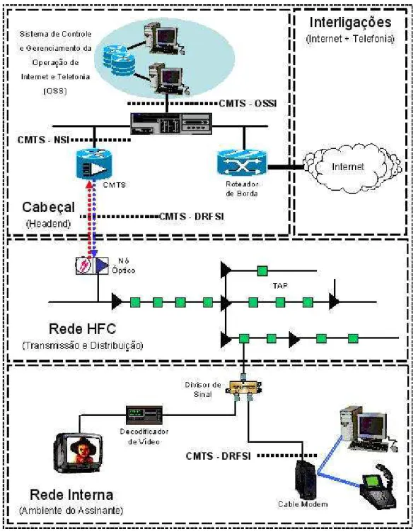
Fig: 4.2 –Basic Architecture of HFC Network data transmission1
In the Figure 4.2, the Cable Modem is the equipment that realizes the interface of the subscription data network, (e.g. Ethernet), over coaxial cable network. The communication between the CMTS (Cable Modem Terminal System) and the CM’s
1
the Headend and other internal networks from subscribers, compounding a large coverage network based in HFC. The interconnection of that large LAN cam is joined with other CMTS using one high speed commutation device, like a Switch. The Switch is able to interconnect many CMTS (Cable Modem Termination System), and other servers to provide large bandwidth gateways, for applications in IP telephony and others providers like Internet. [77].
For the OSS (Operation Support System), it is possible to use for controlling the service plan for the subscriber and manage network parameters to control the Quality procedures requisites for the applications. The Standard DOCSIS establish a data control model for reference OSI (Open Systems Interconnection),[78].
4.2– Engineering Constraints Geometric and Equations for Signal Radiation over HFC Networks
The following equations must be considered for a complete calculation to the forward and reward signal to provide the broadband TV and the internet running well on the typical design.
The quantum efficiency for all wave lengths is expressed as the equation [78-80].
⎟
⎠
⎞
⎜
⎝
⎛
=
h.c
.
q
.
λ
η
ρ
(4.1)Where:
n: quantum efficiency of fotodetector (decimal) q: change of electron (1,60219 x 10⁻¹⁹ Coulombs)
λ: laser wave length (m)
h: Planck´s constant (6,63 x 10⁻³⁴ Joule’s)
c: wave speed propagation in vacuum (3.108 m/s)
In real devices, the quantum efficiency is dependent on the wave irradiation.
In the silicon, it’s in an order of 80% to 90% considering the λ between 850nm a 900nm, or in other words a responsively of average 0,5 A/W, and it’s good for the first window transmition optical fiber. To the Germanium (Ge), the max value occurs in a wavelength of 1300 nm. This value is good for the second window transmition.
For other compositions like InGaAs, the best efficiencies are in 1400nm e 1600nm, appropriate values to the third window transmition with low signal loss [80]. For InGaAS or Ge presents high efficiencies in quantum region of 1300nm and 1550nm, and the HFC network present in practice typical values of 85% [78],[79].
The determination of the signal level of Radio Frequency and their electric field intensity, irradiated for each of its points.
To establish a frequency plan, where the carrier width for each channel is 6MHz, a lot of distortion components have a same nominal frequency. The beating number will depend on the channel plane adopted, and or the number of the phases.
Usually, a Cable TV system is demonstrated by an intermediation methodology determinated by the number of beating of second and third order, for each nominal frequency, respectively:
Second Order: 2.f1 or 2.f2 e f1 ± f2 (2.2)
Third Order: 3.f1; f1 ± f2 ± f3; 2.f1 ± f2 or f1 ± 2.f2 (2.3)
Where: f1, f2 e f3 are carrier nominal frequency
The nominal carrier frequency are arbitrary and not necessary continue. In Figure 4.4 the graphic number of beats of second order for bandwidth of 330MHz – 40 channels
450MHz – 60 channels,
550MHz – 77 channels e 750MHz 110 channels [61], [62].
Figure 4.3 - Distorções de 2ª Ordem Composta [61]
Figure 4.4 - Batimentos Composto de 3ª Ordem [61]
The Fundamentals of RF and Microwave Noise Figure Measurement [62] defines noise figure as the "...degradation in signal-to-noise ratio as the signal passes through the [device under test]." The most commonly accepted definition originated in the 1940s2, which stated that the noise figure (F) of a network is the ratio of the
2
signal-to-noise power ratio at the input to the signal-to-noise power ratio at the output: F = (Si/Ni)/(So/No).
In the previous example, the amplifier output CNR is 8 dB worse than the input CNR, so the amplifier noise figure is 8 dB. The noise figure of an amplifier is independent of input and output levels. Amplifier manufacturers try to reduce the noise figure by optimizing impedance levels and circuit design, and choosing low-noise transistors or hybrids. Typical cable TV amplifier noise figures are in the 7 to 10 dB range. Calculating downstream CNR in a cable network is generally done by first calculating the CNR of each type of standalone amplifier used in the network, and then calculating the CNR of the longest cascade of amplifiers in the network. The cascaded amplifier CNR is then combined with the headend and fiber link CNR using power addition. This exercise yields the overall CNR from headend to the network end-of-line.
Figure: 4.5. –Amplifier Schema System Indoor – Scientific Atlanta Graph Representation for TV Electronic Amplifier Configuration:
nodes of Figure 4.5, where, inside it have a complete operation simplification of the electronic device equivalent circuit in the frequency domain considering in only one simplification equations C1,C2, that’s is the optimization result of full sub-graph constraint satisfactions.
C1: CN =−NT +(O−G)−(NF+L) (4.2)
Where:
CN: Carrier to Noise considering only one amplifier in Node (dB) (MDU) NT : Power Thermal Noise (-59, 16 @ BW = 4MHz) (dbmv)
O : Amplifier Output RF Signal Level (dbmv) G : Amplifier Gain (dB)
NF: Amplifier Noise Graphic Figure (non linear graph) (dB) L: Insertion Loses of Equalization Amplifier (dB)
C2:
⎟⎟
⎠
⎞
⎜⎜
⎝
⎛
−
Δ
−
Δ
=
system chL infop
fm
med
op
EQ
1
(4.3) Where:EQ = Equalization Factor (TILT correction) ∆op: Input differential operational Gain (dB)
in
med
Δ : Differential Input Gain (dB)
chL
fm
: Frequency of forward lower channel (MHz)system
fop
: Operational frequency of the system (MHz)C3: NP = NT -10 × log(BW ) (4.4)
Where:
NP : Noise Power per Hertz – Carrier Forward NT: Power Thermical Noise (dbmv)
C4: NPret = NP -10 × log(BWret ) (4.5)
Where:
Npret: Noise Power per Hertz – Carrier Reward NP : Noise Power per Hertz – Carrier Foward NT: Power Thermical Noise (dBmV)
BW: Bandwidth rate Thermical Noise measure (Hz)
C5: CNRret = -NPret + (I ret - Pdiplex - Pcombiner )- NFret (4.6)
Where:
Npret: Noise Power per Hertz – Carrier Reward NP : Noise Power per Hertz – Carrier Forward I ret: RF Input Power Level Reward sense (dBmV) Pdiplex: Reward Power Level Diplexer Filter (dB)
Pcombiner: Return Amplifier Combiner Power Level insertion loses (dB) NFret: Return Amplifier Noise Figure
C6: CSO = CSO0 − (AO−OR)+ LC + 0,33⋅TC (4.7)
Where:
CSO0: CSO Sum of identical second order Beat Ratios (dB).
OA: Signal Output operational level on amplifier (dBmV).
OR: Signal Output referential level on amplifier (dBmV).
LC: modificação do número de carregamento de canais no amplificador (dB).
TC: Differential Amplifier Gain (tilt) (dB)
C7: CTB = CTB0 − 2 ⋅ (AO−OR)+ LC + 0,8⋅TC (4.8)
Where:
OR: Operational Reference level on Amplifier (dBmV).
LC: Number of loading channel in the Amplifier (dB).
TC: Differential Gain modification (tilt) (dB)
The adoption of the new Inside Home Wiring Rules It will also enhance the availability to the industry and the public of cable system and multichannel video programming systems information In Figure 4.7.
Figure 4.7 – Signal Radiation (leakage) measure method [61]
The Cumulative Leakage Index (CLI) is presented, second the FCC (Federal Communications Commission), regulamentation 76.611,
Where:
: The Length network susceptible to signal radiation (Km);
Ei : Electrical Field in 3m length (μV/m);
Ri: distance of inclination of the power irradiation signal for one point at 3000 meters of the Center system or Cable TV Network (m);
ni: number of radiations of level higher than 50μV/m;
further increased. Due the incremental nature of the implementation engine, is proportionally to number of equations gain efficiency for a larger number of equations.
4.3– The Constraint data model for Network RF Amplifier
Figure 4.8 are shows constraint-base to represent the indoor Amplifier and one Splitter. In the MDU Schema on the left is presented the physical representation for the connection between one amplifier (in door) connected to a splitter by coaxial cables. On right, the Geometric Graph presents the existent relation of geometric constraints by each one, the amplifier A1 and for the splitter S1. Finally, the Equation Graph on the right is illustrated by the equation 4.2 particular equation graph to the amplifier A1.
4.4– The Constraint data model for Passive HFC Network components
A1 S1 S2 Splitter
Amplifier In door
(a) MDU – Schema (b) Geometric - Graph
C1
I
C2
CN
C3 NF
(c) Equation - Graph
components: Splitter, Equalizer, RF Cable, Cable Simulator. Figure 4.9 present a general data model for the passive components logical information, and for each different component the equations and particular characteristics are used. But, the data model and relationship graph will be very similar, specially in the algorithm functionality.
Figure 4.9 – Constraint data model for HFC Passive Components
4.5 – Constraint Satisfaction
The engineers, at the design work, realize a definition for the steps to the project conception. The floor numbers of the MDU schema and the position of the indoor amplifier are necessary to control the forward and reward signal level on the network elements in a sequential process to perform constraints satisfaction.
4.6 – Summary
Chapter 5
Implementation Details
_________________________________________________________
5.1- Introduction
This chapter presents some implementation details of the system proposed and discussed in previous chapters, focusing on the internal MDU (Multiple Dawdling Unit) design, and use the same concept data model. The demonstration of the algorithms proposed is described using a constraint implementation and a constraint manager engine data model for satisfying the engineering equations.
5.2-Constraint Engine Modules Architecture
Figure 5.1 -Hybrid Constraint Engine
5.3 – The Representation of Constraint Equations and Variables
All constraints equations and variables nodes are implemented as classes (object-oriented programming).
Figure 5.2 – Variable Node Data Representation
Figure 5.2 represents the definition of the main data members of the variable node. The NAME is a String of the variable name, the VALUE is the numeric value of the variable, and the others are pointers.
A1 S1 C1 I C2 CN C3 NF Equation Graph Solver Geometric Relationship Graph
(a) (b)
AutoCAD – API – Application Program Interface
Nodes representing the geometric entities and a set or arcs for geometric constraints compose the Geometric Relationship Graph. The direction of the arcs defines the geometric direction and the propagation changes are propagated in the design.
The Implemented Graph configures a relationship between two geometric entities, and these entities are referred to as reference and target geometric entities, according to graph pointers. This information is stored as the fields RefGO and TarGO, denominated as Constraint Edge, in data structure Figure 5.3.
TYPE
RefGO
TarGO
Figure 5.3 - Geometric Constraint Edge
In this case, is the data structure used to define the main data member of a node in the relationship graph. The GEOMETRY field maintains a pointer to the geometric entity created by the Constraint Manager.
Figure 5.4 – Node Relationship Graph – Data Structure Representation
GEOMETRY – Maintain a pointer to the geometric entity (AutoCAD Handle). STATUS – Indicate the (Inheritance) “logical position”. .
IN-LIST and OUT-LIST – Indicate the connection of geometric entities representing the design model inside the graph.
GEOMETRY STATUS IN-LIST OUT-LIST
C1 C2 Cn
5.5 – The Graphical User Interface (GUI)
The GUI is based on AutoCAD MAP – SDK – Software Developer Toolkit. [Customization Guide Autodesk]. The capabilities of AutoCAD MAP interfaces interaction provide a power tool to follow the computer graphics standards and open source concepts to implement and easy to adopt tool and open source data base model, for many different acknowledgments areas of science research. The AutoCAD®-based interface is a good tool for extend design information to users in a huge and traditional CAD community.
Objectives for Interact with AutoCAD – GUI environment and Constraint Manager Interface:
• Deliver a product that requires CAD software functionality but is not targeted at traditional CAD users.
• Build products that can read and create DWG™ files that are fully compatible with AutoCAD DWG files.
• Create host programs that run an application in a child window or through a web page.
• Deliver products with scaled feature sets at scaled price points and provide an AutoCAD-based platform that cannot be customized or extended by end users
• Replace an aging CAD software system and take advantage of new AutoCAD software technologies.


![Figure 4.7 – Signal Radiation (leakage) measure method [61]](https://thumb-eu.123doks.com/thumbv2/123dok_br/16145967.705290/64.892.130.512.423.755/figure-signal-radiation-leakage-measure-method.webp)
