i
Project
Master Degree in Mechanical Engineering - Industrial Production
Development, programming and start-up of an
interchangeable 3D-printing module
Hugo Miguel Lopes Oliveira
ii
i
Project
Master Degree in Mechanical Engineering - Industrial Production
Development, programming and start-up of an
interchangeable 3D-printing module
Hugo Miguel Lopes Oliveira
Master Project Report realized under the supervision of Prof. Dr.-Ing. Uwe Berger from the University of Aalen and Prof. Dr. Joel Vasco from Polytechnic Institute of Leiria.
ii
i
Acknowledgements
I would like to express my gratitude to Polytechnic Institute of Leiria and the University of Aalen for the opportunity and all the support to do this international mobility.
I would like to acknowledge the efforts of my supervisors Prof. Dr.-Ing. Berger and Prof. Joel Vasco, and thank them for providing their knowledge, constructive observations, patience and constant support. I also would like to thank to Mr. Mäule and Mr Sorg for all the assistance and advice during the realization of this project. Without their guidance it would not be possible to deliver consistent results and conclude this project on time.
I would like to thank to my family: my father, mother and sister for their love, faith in me and support during all the moments of my life.
Finally, I would like to thank to my girlfriend, friends and colleagues for their friendship, advice, encouragement and continued support over the years.
ii
iii
Resumo
Este trabalho teve como objetivo o desenvolvimento e aplicação de um módulo de impressão 3D (fabricação aditiva) numa máquina de controlo numérico (fabricação subtrativa) criando assim um ambiente de fabricação hibrida que poderá oferecer as vantagens de ambos os processos. Qualquer máquina de comando numérico poderá ser convertida num equipamento aditivo usando este módulo de deposição de material, que poderá ser inserido na máquina à semelhança de uma ferramenta comum, sendo o mesmo colocado na cabeça de rotação da máquina num processo simples. O módulo será capaz de ler a rotação da cabeça da máquina e utilizar essa informação para executar diferentes comandos e ações.
Tendo em foco a criação de um sistema funcional de baixo custo, foi utilizada uma placa Arduino para controlar todo o sistema. As partes constituintes do módulo são, na sua grande maioria, peças impressas por estereolitografia, permitindo assim obter peças com elevada precisão, acabamento superficial e geometrias complexas.
Os resultados obtidos na primeira fase de testes não foram totalmente de acordo com o esperado, pois foram encontrados vários problemas que não tinham sido previstos ou tidos em conta aquando o desenvolvimento inicial do módulo. Várias soluções e correções foram realizadas de modo a eliminar ou minimizar os problemas encontrados.
O sistema de controlo de temperatura realizado apresentou resultados precisos e em tempo real, assim como o sistema de leitura de rotação da árvore da máquina.
O maior desafio encontrado foi o sistema de alimentação do filamento, que após várias modificações estruturais, sofreu melhorias e apresentou resultados satisfatórios para a aplicação em questão contudo com fortes possibilidades de melhoria.
iv
v
Abstract
This report has as main objective the development and application of a 3D printing module (additive manufacturing) in a computer numeric control (CNC) milling machine (subtractive manufacturing) creating a hybrid manufacturing environment that could offer the advantages of both methods. Every CNC milling machine using this 3D printing module could be converted in a 3D printer by changing from a regular tool to the 3D printing module which is applied in the spindle of the machine in a very simple process. This module is equipped with a system capable of reading the spindle rotation speed, and uses that information to set up different commands and actions.
Focused in the development of a low-cost system, there is used an Arduino board to control all the systems needed to work with the module. Most of the parts of the module are printed in a 3D printer that uses the stereolithograph technology, being able to create parts with complex shapes, high precision and good surface finishing.
The experimental results obtained in the first tests were not as expected. Many problems that haven’t been taken in consideration when the initial development of the module was done. Many solutions were found and some corrections were done to eliminate or minimize those problems.
The temperature control system and the revolutions per minute reading system shown very good results in the experimental tests.
The biggest issue faced was related with filament feeding system. Many structural modifications were implemented to improve it, with better performance, obtaining acceptable final results, however with significant possibilities for improvement.
vi
vii
List of Figures
Figure 1 - FDM process [6] ... 6
Figure 2 - Principle of SLM technology. [8] ... 7
Figure 3- Subtractive manufacturing: Milling process [11]. ... 8
Figure 4 – Programming and simulation of parts using CAM software [12]. ... 9
Figure 5 - Hurco 3D printing head CNC adapter [13]. ... 10
Figure 6 - Milling of a 3D FDM printed part [14]... 11
Figure 7 - DMG Mori LASERTEC 65 3D Hybrid metal deposition [15]. ... 12
Figure 8 - 3D printing module. ... 13
Figure 9 - Arduíno Mega 2560 board [18]. ... 14
Figure 10 - Viper Si2 SLA System 3D printer used to print parts [20]. ... 17
Figure 11 - Preparation of parts to print using software 3D Lightyear 1.5. ... 18
Figure 12 - Some of the printed parts. ... 18
Figure 13 - Diagram with the main components of the module. ... 19
Figure 14 - Process diagram of the Arduino code. ... 20
Figure 15 - LCD Display. ... 22
Figure 16 - Motor 1 and A4988 driver electrical diagram. ... 22
Figure 17 - Photo sensors of lever 2 and 3. ... 23
Figure 18 - Electrical diagram of the photo sensor. ... 23
Figure 19 - Power supply diagram. ... 24
Figure 20 - Working principle of RPM counter using a perforated disc [24]. ... 26
Figure 21 – Left: Perforated disc used for tests. Right: Motor, perforated disc and optical sensor. ... 27
Figure 22 - Electrical diagram of the RPM reader photo sensor. ... 27
viii
Figure 24 - Heating block. ... 31
Figure 25 - 4 Channel relay electrical diagram. ... 31
Figure 26 - Temperature system diagram. ... 32
Figure 27 - Problems found in the feeder mechanism. ... 34
Figure 28 - Components and modifications in the feeder wheel. ... 35
Figure 29 - Original system with nozzle blocks very close to main body... 36
Figure 30 – New system with an isolation plate. ... 37
Figure 31 - Fans to help reducing the heat transfer to the main body. ... 38
Figure 32 - Assembly parts for the tool holder fixation. ... 39
Figure 33 - View of the fitting groove for centering the spacer ring. ... 40
Figure 34 - Tool holder mounted in the module. ... 40
Figure 35-Module mounted in the CNC machine. ... 41
Figure 36 - Filament melting in the metal tube. ... 42
Figure 37 - Fan added to cool down the metal tube. ... 42
ix
List of Tables
Table 1 - Project plan... 3
Table 2 - List of parts fabricated by the mechamical department. ... 16
Table 3 - List of printed parts in the SLA printer. ... 16
Table 4 - Pinout description of the components connected to the Arduino. ... 21
Table 5 - Current consumption of each component. ... 25
Table 6 - Test results for temperature readings. Values in °C. ... 33
Table 7 - Results of time measurement tests. ... 33
Table 8 - RPM values. ... 41
x
xi
List of Acronyms
CNC Computer Numeric Control SLM Selective Laser Melting RPM Revolutions Per Minute AM Addictive Manufacturing FDM Fused Deposition Modeling DOD Directed Energy Deposition SL Stereolithography
SLA Stereolithograph Apparatus STL Standard Tessellation Language CAD Computer Aided Design
CAM Computer Aided Manufacturing
UV Ultraviolet
ISR Interrupt Service Routine
PLA Polylactide
ABS Acrylonitrile butadiene styrene
xii
xiii
List of Contents
Acknowledgements ... i
Resumo ... iii
Abstract ... v
List of Figures ... vii
List of Tables ... ix
List of Acronyms ... xi
List of Contents ... xiii
1. Introduction ... 1
1.1 Objectives ... 1
1.2 Project Plan ... 2
2. State of the Art ... 5
2.1 Additive Manufacturing ... 5
2.2 Subtractive Manufacturing... 8
2.3 Hybrid Manufacturing ... 10
3. Experimental Setup ... 13
3.1 Current State of Development ... 15
3.2 Stereolithographic 3D Printing ... 16
4. Experimental Work ... 19
4.1 Arduino and Electronic Components ... 19
4.2 RPM Counter ... 26
4.3 Temperature Control System ... 29
4.4 Filament Feeder ... 34
4.5 Cooling System for Nozzles ... 36
5. Test Results and Analysis ... 39
6. Conclusions ... 45
6.1 Future Work and Optimizations... 47
References ... 49
xiv
1
1. Introduction
The current report relates the final project from the Master program in Industrial Production from the Polytechnic Institute of Leiria in Portugal. This final project was done during an internship in the University of Aalen in Germany with the duration of four months, from March to June 2017. In the University of Aalen I was assigned to Prof. Dr.-Ing. Berger who guided me during the internship with the help of Mr. Mäule and Mr. Sorg.
The development and application of a 3D printing module (additive manufacturing) in a CNC milling machine (subtractive manufacturing) aims to create an hybrid manufacturing environment that could offer the advantages of both methods. Every CNC milling machine using this 3D printing module could be converted in a 3D printer by changing from a regular tool to the 3D printing module which is applied in the spindle of the machine in a very simple process. This module is equipped with a system capable of reading the spindle rotation speed, and uses that information to set up different commands and actions.
I was assigned to a project that consisted in the development, programming and start-up of an interchangeable 3D printing module, a project with the department of Mechatronics and a continuation of a previous thesis. This project was very challenging since it required knowledge in mechanics, electronics, programming and CAD design, however it was a great opportunity to expand my knowledge in these different areas.
1.1 Objectives
The main goal of this project was to optimize the design and software of the interchangeable 3D printing module to be possible to create a real test environment mounting the 3D printing module in a CNC machine tool. With this will be possible to convert a CNC milling machine in a 3D printer.
2 Since the previous thesis didn't result in a completely working model, an optimization and development process was necessary to be able to start the module in a CNC milling machine. Was also necessary to develop new features and systems. A system capable of reading the spindle rotation needs to be created. This system will be responsible for reading the spindle speed and that information will be used to determine which nozzle will be activated or if there will be no material extrusion.
Also a temperature system needs to be developed in order to control individually the temperature of each nozzle, using a closed loop system which will allow the nozzle to maintain a constant temperature.
The Arduino code needs to be rebuild to be able to receive and send information to the new developed systems and to make the necessary calculations for RPM reading and the temperature reading.
The feeding system needs improvements and new parts should be printed to ensure that the mechanical parts will work properly and without looseness.
After all these implementations, the 3D printing module will be ready to be tested in a CNC machine.
1.2 Project Plan
At the start of the project and together with Mr. Berger, a planning was made to have an overview of all tasks that could be achieved to complete the main objective of this project. This planning was a guide line that should be followed to complete all the tasks on time however changes could be done. In Table 1 it is possible to observe the complete initial planning.
The first step was analyzing the documentation about the actual state of the project to understand what was done and how it was done. Also to get familiar with all components and its working principles.
In the second step the startup of the module was done by uploading the existing program code to the Arduino to observe what was working and in which conditions.
3 In the third step an optimization of existing hardware was done by correcting wrong projected parts, design of new parts and adding more components to the system to complete new task.
The fourth step was optimization/writing new code for the new components added to the system and creation of a test environment to the all the modules.
The fifth step was starting the module in a CNC machine by mounting it in the spindle. The main objective was reached in the sixth step were final tests to the system were done. Mounted in the CNC machine and start to extrude material for optimization of extrude speed, temperatures and other parameters.
The final step was to elaborate a report about all the work done and make a final presentation.
Table 1 - Project plan.
Main tasks Work
step Targets; Comments Week Support
Initial training of 3D printing, introduction to components of a 3D printing module
1 Literature,
Documentation 11 Berger
Start-up of an existing 3D
printing module 2 Laboratory Work 12 Berger, Mäule
Modification and optimization
of hardware 3
Development and test
of control software 12-18 Berger, Mäule
Adaption of control software,
creation of test environment 4
Test of stepper feeds
and spindle speed 14-18 Berger, Mäule
Start-up on CNC machine tool 5 Real test environment 18 Berger, Mäule, Sorg
Test and optimization of the extrusion head using ABS, PC Support material (2 nozzles)
6 Test in workshop 19-24 Berger, Mäule, Sorg
4
5
2. State of the Art
2.1 Additive Manufacturing
Additive Manufacturing (AM) technologies refer to a group of technologies that build physical objects from Computer Aided Design (CAD) data by the consecutive addition of liquids, sheet or powdered materials in ultra-thin layers, contrary to conventional subtractive manufacturing technologies like cutting, lathing, turning, milling [1].
With additive manufacturing it is possible to produce parts of big geometrical and structural complexity. AM is regarded as a nascent technology entailing great disruptive potential, triggering a revolution of product development processes in various industries, and enabling value creation for new business models, new products and new supply chains. In contrast to the subtractive manufacturing processes, additive manufacturing processes add material to manufacture parts with the desired geometries. This enables waste reduction because unwanted material will not be added. Particular process steps, such as drilling, do not have to be applied; for example, a hole is formed by not adding material in the desired position. In 2010 a working group was set up by the American Society for Testing and Materials (ASTM) to create the F42 standard that formulates a set of directives that classify the range of additive processes into seven categories [2].
The seven categories referenced in ISO TC 261, transposed from ASTM F42, are: 1. VAT Photopolymerisation
2. Material Jetting 3. Binder Jetting 4. Material Extrusion 5. Power Bed Fusion 6. Sheet Lamination
7. Directed Energy Deposition
Despite the AM processes classification above, the AM-technologies can be differentiated into two major groups: laser-based and nozzle/printing head-based technologies.
6 Laser-based processes, e.g. Selective Laser Sintering, employ the principle of layer-wise solidification by applying energy via laser. Individual, thin layers of metal, plastic or sand powder are bonded with previous layers by laser sintering, laser melting or laser light solidification. In nozzle-based processes, e.g. Fused Deposition Modeling (FDM), wire-shaped thermoplastics are partly melted and extruded in the nozzle. The nozzle moves to produce the profile of the part. Due to the thermal fusion, the material bonds with the layer beneath and solidifies [3] [4].
FDM is the extrusion process used in this work. It is an extrusion process in which thermoplastic material (filament) is continuously squeezed through a nozzle and deposited on a substrate. The material’s energy surfaces fuse to the substrate and after cooling down, a permanent connection is available. In Figure 1 it is possible to see an explicative image about the FDM process [5].
Figure 1 - FDM process [6]
In contrast to other additive processes, the FLM is suitable for both prototyping and production applications because parts with a high mechanical load capacity can be produced. Generally, plastics are used with fused layer modeling, for example, polylactide (PLA), acrylonitrile butadiene styrene (ABS), polycarbonates (PC), or combined plastics, for example, PC-ABS.
7 A very known laser-based technology is Selective Laser Melting (SLM), that consists in using a focused laser beam to melt powdered material into a solid object.
SLM is a method in which material in powder form is applied in layers on a working platform, and then is fused in a selective manner, using high-power laser. The laser is controlled by the scanner on the XY plane and the platform is moved in the Z direction. The powder for each subsequent layer of the object is applied from a movable container and laid on the previous layer, providing permanent connection across the entire object. After a pattern is melted on a layer, the building platform moves down by a thickness of a layer, new powder is deposited and leveled and the process is repeated until the complete part is built, as it is illustrated in Figure 2 [7].
Figure 2 - Principle of SLM technology. [8]
The process starts by slicing the 3D CAD file data into layers, creating a 2D image of each layer. The 3D file format is the industry standard .stl file extension used on most layer-based 3D printing technologies. This file is then loaded into a file preparation software package that assigns parameters, values and physical supports that allow the file to be interpreted and built by different types of additive manufacturing machines.
With SLM it is possible to produce highly customized parts with added improved functionalities that are not possible through traditional processes. Small tolerances can also be achieved and compared to conventional processes it reduces waste material. [9]
8
2.2 Subtractive Manufacturing
Subtractive manufacturing is a process by which 3D objects are constructed by successively cutting material away from a solid block of material. Subtractive manufacturing can be done by manually cutting the material but is most typically done with a machine tool. Modern machine tools are controlled by a computerized numerical control (CNC). For this reason, manufacturing processes, for example, drilling, turning, and milling, are also referred to as CNC machining when the machine tool is controlled by a computerized numerical control. The main task of the machine tool is to control the relative motion of the tool and the workpiece. All these tools cut away unwanted material to manufacture a part with the desired geometry creating waste material which can be recycled. In Figure 3 is possible to see the milling process where a tool rotating at high speed removes the unwanted material to shape the final part [10].
Figure 3- Subtractive manufacturing: Milling process [11].
Subtractive processes offer many advantages, even over additive processes. The surface finish that can be achieved is high quality and doesn’t create the “stepped” surfaces often found in many additive processes. The surface finish quality can be functionally important if parts must slide and cosmetically important if the prototypes are to be used in market testing.
However, because the process is removing material instead of adding it, milling undercuts can sometimes be difficult. Machining also tends to be more expensive than the additive processes.
9 One long viewed disadvantage of subtractive manufacturing has been the necessity of programming required using CAM software for more complex geometries to create instructions and information on an object and turn it into machine executable code (G-code). In Figure 4 it is possible to see an example of CAM programming to generate G-code [12].
Figure 4 – Programming and simulation of parts using CAM software [13].
But the automation of tool path generation is the key that makes subtractive technologies competitive with the additive methods. Today’s vendors have found ways to make CNC tool-path generation easy and efficient.
10
2.3 Hybrid Manufacturing
Hybrid Manufacturing is the term used to describe combining metal additive manufacturing (AM) technology with conventional, subtractive technology, enabling each process to work together on the same machine and even on the same part. Hybrid Manufacturing reduces the risks and costs associated with adopting AM technology, providing a more pragmatic and evolutionary pathway for industrial manufacturers.
Since hybrid manufacturing incorporates both additive and subtractive technologies, fabrication and precision can be attained in a more efficient and unified environment. The combination is meant to enable greater design freedom, flexibility and intricacy in creating complicated parts or those with radical geometries that conventional manufacturing was not able to produce [14].
In 2014, HURCO Companies Inc. has filed a U.S. patent application for new technology combining 3D printing and CNC milling. A FLM extrusion head is interchanged to turn a CNC milling machine in a 3D printer. A decoder evaluates the spindle speed to generate control commands for the extrusion process [15].
11 Another interesting subject, which can also be a future optimization for this project, is to use CNC milling operations in 3D printed parts. As a secondary process, CNC machining of 3D printed parts can provide additional dimensional accuracy on additive parts while maintaining all the benefits of 3D printing technologies. like FDM.
Figure 6 - Milling of a 3D FDM printed part [16].
FDM works with engineering-grade thermoplastics that are used for production applications with high requirements. FDM is an ideal choice for production parts because of the unparalleled design freedom possible with the technology while achieving durability and excellent strength-to-weight ratios. The addition of CNC machining to FDM part manifests in even more accurate parts in lightweight and robust materials [16].
Additionally, the combination of the two processes can be quicker than most traditional manufacturing methods. Even accounting for printer set up, build, finishing and machining, the additive plus machining method is faster than designing and producing a tool for injection molding. It also allows for greater flexibility to make design improvements [16].
12 The company DMG MORI launched the DMG Mori LASERTEC 65 3D Hybrid, a CNC machine that uses the Directed Energy Deposition (DOD) 3D printing technology to create parts, layers after layer [17].
This hybrid 3D printer has integrated laser additive manufacturing into a fully-fledged 5-axis milling machine. This hybrid solution combines the flexibility of laser deposition welding with the precision of conventional milling for the additive manufacturing of finished quality parts with maximum precision. [17]
This 3D printing technique, similar to welding, involves a metal powder feed that facilitates complete machining without a processing chamber for up to 10 x faster production than using a powder bed (like SLM), the melted material is directly jetted on the future 3D part. The flexible switching between laser and milling operations allows for the direct machining of areas that could no longer be reached on a finished part. [17]
Figure 7 - DMG Mori LASERTEC 65 3D Hybrid metal deposition [17].
Up to now, additive technologies have been used to generate prototypes and small parts. By combining both, additive manufacturing via powder nozzle and the traditional cutting method in one machine, totally new applications and geometries are possible. Especially large workpieces with high stock removal volumes are now possible to be machined in an economical way. The flexible change between laser and milling operation allows the direct milling machining of sections which are not reachable anymore at the finished part [17].
13
3. Experimental Setup
The current project of developing and programming an interchangeable 3D printing module was based on the work of a previous thesis from Gilles Paermentier [18].
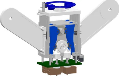
The additive technology used in the project is FDM and the material of the filament used is ABS with a diameter of 1,75mm. The 3D printing module has a relatively simple design and most components are made of plastics and the module has a compact shape. The 3D model of all the components can be seen in Figure 8.
Figure 8 - 3D printing module.
An important feature is the possibility to mount the module in a milling machine without the use of specialized tools. A hole in the top plate ensures that a standard tool holder can be attached to the module in the top plate. Bearings will make sure that the tool holder can spin freely without moving the module. If the module would move, the position of the nozzles will change and the print job will be ruined and the module could be damaged or destroyed. When mounting the tool holder on the module, a perforated plate will be attached. The plate will rotate at the same speed as the tool holder and a sensor will register the speed. This speed is measured and converted in commands for all the electrical components, it will decide when one of the four nozzles will be activated to start a printing sequence. This function takes away the need to have a direct connection with the software of the milling machine. Only properly G-code is needed to control the module. When the module is mounted, the printing can start. Since there are four nozzles, it is possible to print four
14 different materials. Each nozzle has its own separated feeding system. On the sides of the module are two arms where four rolls of filament thread can be placed.
There is no need for an external source to feed the filament. Once the thread has left the role, it goes inside the main body of the module. In this component four levers can be found, two in the front compartment and two in the back. Each lever has two guiding wheels. The top wheel is pressed against a camshaft. A spring attached to the opposing levers, makes sure they are pulled towards each other and they always press against the camshaft. When the camshaft is moved in the correct position, the lever will tilt forward. A sensor will register which lever is tilted and makes sure that the correct nozzle is activated. The filament thread now moves through a channel in the lever and arrives in front of the second guiding wheel. Because of the tilted position of the lever, the thread is pressed between the guiding wheel and a feeder roll. By using pressure and friction the rotation of the feeder roll will start the feeding of the filament. The thread will first be fed in the filament feeder, a small tube that guides the thread towards the nozzle, and will arrive in the nozzle where it will be melted and extruded.
There are two stepped motors which controls the camshaft and the filament feed speed. Each one of the four nozzle blocks have attached a temperature sensor and a heater which are used to read the temperature and heat the block, respectively. Optical sensors installed in the module will read the actual position of each lever and another one is used to determine and calculate the actual spindle speed.
For controlling all the electrical components an Arduino Mega 2560 was used. Arduino is an open-source electronics platform based on easy-to-use hardware and software. Arduino boards is able to read inputs and turn it into an output. The microcontroller chip in the Arduino board is programable and the uploaded code will determine the system functionality [19].
15
3.1 Current State of Development
During his project and according to Mr. Gilles, a lot of time was spent in design and optimization of the parts of the module, in learning the Arduino language and writing the code. Because of that, not all the goals of the project could be achieved by Mr. Gilles and the design and development of the module wasn’t finished [18].
After analyzing and testing the work done by Mr. Gilles, it was possible to understand which tasks were necessary to work on. The system and Arduino code to read the spindle speed was not working properly and the perforated disc had an insufficient number of holes what results in a very low accuracy of the measured spindle RPM.
The temperature sensors to be used didn’t exist, like the Arduino code to calculate the temperature.
The nozzle blocks were fixed under the main body by nylon isolators and when heating the nozzles, a lot of heat was transferred to the main body. The main body was reaching very high temperatures and would be destroyed in just a few minutes. The isolation and fixation system for the nozzles needed to be improved and redesigned to correct the heating problems.
The feeding system didn’t have enough strength to feed the filament, what will result in a feeding failure of the filament to the nozzle for material extrusion. The feeding guiding wheel was loose, what was contributing for this situation. Optimization to the feed system components was necessary.
16
3.2 Stereolithographic 3D Printing
During the realization of this project there was the need to use parts that were designed with CAD software. Some of the parts were manufactured by the mechanical department of the university using the provided 2D drawings of the parts. This drawings can be seen in the appendix section. In Table 2 it is possible to see the list of parts fabricated by the mechanical department.
Table 2 - List of parts fabricated by the mechamical department.
Part designation Material
Isolation plate Thermosets Isolator Teflon Metal ring Aluminum Metal part Steel
Most of the parts used in this project have been printed in a Stereolithograph Apparatus (SLA) 3D printer available in the laboratory. In Table 3 it is possible to see the parts printed using this method during the elaboration of this project.
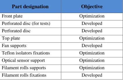
Table 3 - List of printed parts in the SLA printer.
Part designation Objective
Front plate Optimization Perforated disc (for tests) Developed Perforated disc Developed Top plate Optimization Fan supports Developed Teflon isolators fixations Optimization Optical sensor support Optimization Filament rolls supports Optimization Filament rolls fixations Developed
Stereolithography (SL) is an additive manufacturing process that works by focusing an ultraviolet (UV) laser into a tank with photopolymer resin. Stereolithography is one of several methods used to create 3D-printed objects. It's the process by which a SLA (Figure 10) converts liquid plastic into solid objects and it was patented as a means of rapid prototyping in 1986 by Charles Hull [21].
17
Figure 10 - Viper Si2 SLA System 3D printer used to print parts [22].
With the help of a CAD model of the object to be printed, the UV laser is used to draw a pre-programmed design or shape on to the surface of the photopolymer tank. Because photopolymers are photosensitive under ultraviolet light, the resin is solidified and forms a single layer of the desired 3D object. Then an elevator platform descends a distance equal to the thickness of a single layer of the design (typically 0.05 mm to 0.15 mm) into the photopolymer tank and process is repeated for each layer of the design until the 3D object is complete.
In 3D printing - or additive manufacturing - CAD files must be translated into a "language" or file type that 3D printing machines can understand. Standard Tessellation Language (STL) is one such file type and is the language most commonly used for Stereolithography [23]. To make sure that the prints adhere to the print platform and do not float around in the resin tank, the SLA printer require the use of supports. This supports look like thin ribs with only small tips touching the model. The number of supports, their location, where they touch the model and the structure is calculated by the software and it depends on the shape, orientation and weight of the part being printed [24].
After converting the CAD files to STL, it is uploaded to the software 3D Lightyear 1.5 to prepare the model for the SLA printer. The software environment can be seen in Figure 11.
18
Figure 11 - Preparation of parts to print using software 3D Lightyear 1.5.
The model is positioned and the supports are created automatically. A BFF file type is then created and uploaded to the SLA printer. In the printer is given the order to start to print the part. After printed, it is cleaned with a liquid solvent to remove the excess resin and the supports. The final step is to bake the printed object in an ultraviolet oven to further cure the plastic [21] [23].
In Figure 12 it is possible to see some of the printed parts used in this project.
Figure 12 - Some of the printed parts.
One of the biggest advantages of this type of printing is the printing speed and precision but on the other hand, this a quite expensive process because of the initial cost of the machine and the cost of the resin used to print parts.
19
4. Experimental Work
4.1 Arduino and Electronic Components
After understanding the working principle of the module, it’s components and the Arduino code, the following diagram (Figure 13) was done. It represents the interaction of the different components with the Arduino board.
Figure 13 - Diagram with the main components of the module.
The Arduino code is organized in the following way:
1 - Libraries declaration 2 - Variables declaration 3 – Pin definition 4 - Setup function 5 – Auxiliary functions 6 – Loop function
The setup function runs only one time when the program is executed, and in this function there is the definition of the pins as input or output and the initialization of the LCD. The loop function, as the name says, runs constantly and is in this function where the main code is written. The auxiliary functions there are all the necessary functions for the loop function, for example the function to read the spindle speed, temperature, to initialize the filament feed, to determine which lever is active, etc.
20 In the Figure 14 it is possible to see the process diagram of the Arduino code. Firstly, the spindle speed is determined and if it is between the boundaries of the pre-defined speeds it starts to execute the rest of the program. The correct lever is activated and the heaters start to heat up the nozzle to the desired temperature. The feed occurs only if the nozzle is in the correct temperature, otherwise the program waits two seconds and then check the temperature again. If the spindle speed changes to a value outside of the boundaries the feeding system stops.
21 In the next table is a description of the components which are connected to the Arduino board. The Table 4 has the information about the components which are connected to each pin and related information.
Table 4 - Pinout description of the components connected to the Arduino.
Component Code Signal I/O Pin Meaning State
PT1000
TS1
Analog Input 12
Reads the voltage
in actual PT1000 - TS2 13 TS3 14 TS4 15 Relay Board RH1 Digital Output 22 Activates the relays 0 = ON 1 = OFF RH2 23 RH3 24 RH4 25 Step Motor 1 (Feeder) M1_DIR
Digital Output 34 Rotation Direction 0 = CW 1 = CCW M1_STP 35 Rotation Speed 0 = Stop 1 = 1step
Step Motor 1 (Camshaft)
M2_DIR
Digital Output 30 Rotation Direction 0 = CW 1 = CCW M2_STP 31 Rotation Speed 0 = Stop 1 = 1step
Optical Sensor (Levers) PI_1 Digital Input 46 - 0 = Lever Inactive 1 = Lever Active PI_2 47 PI_3 48 PI_4 49 Optical Sensor
(RPM reader) PI_5 Digital Input 3 Interrupt Pin
0
=Inactive
1 = Create Interrupt
LCD Display - I2C - 20 SDA - - I2C - 21 SCL
22 The LCD display shows the current spindle speed and the temperature is only shown if the respective nozzle is activated. In Figure 15 it is possible to see an image of the LCD showing the spindle speed and temperature.
Figure 15 - LCD Display.
The two stepper motors are used to rotate the camshaft and to feed the filament. Each of the motors need a driver interface which allows to control the direction of rotation and speed. The electrical diagram of motor 1 and the respective driver can be seen in Figure 16.
Figure 16 - Motor 1 and A4988 driver electrical diagram.
VDD is the logic power supply which is powered by the Arduino and the VMOT is the motor
power supply. The pins 1A, 1B and 2A, 2B are the coils of the motor. The pins DIR and STEP are connected to the Arduino board, and define the direction of rotation and speed. The connections for motor 2 is similar to motor 1, and the same diagram can be used.
23 To detect the position of each lever, there are four photo sensors. These sensors are fixed in the main body, and as the lever moves outward or inward the sensor detects it or not. In Figure 17 it is possible to observe two photo sensors.
Figure 17 - Photo sensors of lever 2 and 3.
The sensor on the left is being interrupted by the pin on the lever, and the output is 0V. The sensor on the right is not being interrupted between the receptor and the emitter what means the output is 5V. Only one of the photo sensors can be in a high state at once. If more than one are in high state at the same time, there is a failure in the levers system.
The sensors require additional electronics and the electrical diagram can be seen in Figure 18. The four photo sensors used in the levers have the same electrical diagram but are connected in different inputs in the Arduino.
24 To power all the electronics and components, was used a variable power supply from 0V to 33V and a current of 4A with one output. Many of the components used have different working voltages, and to be possible to use only one power supply, a voltage regulator was done, to be possible to have a 12V output and 5V output. The stepper motors and the four cartridge heaters were supplied using 12V. The 5V power supply was used for the relay board and the fan.
The Arduino board is also supplied using 5V, however, it was supplied via USB cable from a computer due to regular tests and modifications to the Arduino code which needs to be uploaded frequently. In the future, the 5V power is supposed to supply the Arduino and related electronics.
The two stepper motors are connected directly to the 12V power supply. Each cartridge heater is connected to the power supply through a relay which function is to turn on or off the heaters. To have a 5V power supply was used the voltage regulator TS7805 which has a maximum input voltage of 35V for an output of 5V and a maximum current of 1A, which is enough for this application. A heat dissipator was mounted in the TS7805 to dissipate the heat caused by the current passing through the regulator [25].
The two capacitors in the circuit are used for stabilization of the operation of the circuit. The relay board and the fan are also connected to the 5V output. In Figure 19 it is possible to observe the power supply and all its components.
25 The main power supply is limited to 4A and this limitation can’t be exceeded. The current consumption of each component/board is described in next table.
Table 5 - Current consumption of each component.
Component Current [A]
Stepper motor (each) 0,4
Heater 3,33
Relay (each) 0,04
Fan (each) 0,18
Total 4,1A
As it can be seen in Table 5, the current consumption is slightly superior than 4A. To not exceed the maximum current of the power supply the two fans were used for its own tests and disconnected for the main tests with all the components, since it was not affecting the operation of the module or other components. Each one of the stepper motor as a current consumption of 0,4A, however only one motor works at the same time. The same situation happens with the cartridge heaters and the relays.
26
4.2
RPM Counter
Fort the 3D printing module to know which lever to activate for choose which material to extrude, it needs to know the spindle rotation. There was the need to implement a system which can read the spindle rotation accurately and with a fast response rate.
A disc with grooves distributed along a circumference and an optical sensor was used as an encoder. The disc is attached to the spindle machine and, as it turns, the holes in the disc opens and closes a circuit through the optical sensor, generating a pulse train that can be used to determine the rotation speed of the spindle by counting the number of pulses in a known interval of time.
The optical sensor used for this application is the TCST 2103. This optical sensor sends a positive pulse (5V) every time the receiver and the transmitter are not blocked (holes in perforated disc). When the receiver and the transmitter are blocked, it cannot communicate and the output is 0V. In Figure 20 it is possible to observe the working principle of the optical sensor and the perforated disc.
Figure 20 - Working principle of RPM counter using a perforated disc [26].
To count the motor’s revolutions per minute there was the need to register every time there was and interrupt, and for that was used the interrupt pin in Arduino (pin 3). This pin generates an interruption every time it receives a positive pulse (from 0 to 5V) from the optical sensor. In Arduino program code was used an Interrupt Service Routine (ISR). This ISR is called every time an interrupt occurs. Using this ISR it is possible to counts all the interrupts from the optical sensor [27]. Knowing the number of pulses and the number of holes of the perforated disc, an interval of time of 0,2 seconds was defined. During this interval of time the number of pulses are counted and calculations are done in the Arduino code to calculate the actual RPM.
27 The perforated disc used in tests was designed using CAD software and printed in a stereolithographic 3D printer. For testing purposes was used an auxiliary 4,5 - 15V DC motor with the perforated disc attached and a support for the optical sensor. In Figure 21 is possible to observe the 3D model of the perforated disc and the mounted system for tests.
Figure 21 – Left: Perforated disc used for tests. Right: Motor, perforated disc and optical sensor.
The optical sensor has four pins, two of them connected to Vcc provided by the Arduino and the other two are the E-pin (emitter) and D-pin (detector). The emitter is connected to Vcc in series with a 220Ω resistor. The detector is connected to the pin 3 of Arduino (interrupt pin) and to Vcc with 1kΩ resister in series. It is possible the observe the electrical diagram in Figure 22.
Figure 22 - Electrical diagram of the RPM reader photo sensor.
Using a perforated disc with 12 holes for the first tests resulted in very low resolution of the final RPM value. According to the formula (1), using a perforated disc with 12 holes and a ΔT of 0,2 seconds the final resolution will be 25 RPM, which is very rough value.
28 To have a better resolution the perforated disc was redesigned with 200 holes and with this new number of holes and for the same ΔT the final resolution will be 1,5 RPM. This value using the perforated disc with 200 holes is very acceptable.
The formula used to calculate the RPM value is the following.
𝑅𝑃𝑀 = 60𝑠 × 𝑁𝑝
𝛥𝑇 × 𝑁 (1)
Where:
RPM – Revolutions per minute; Np – Number of pulses;
ΔT – Measuring interval time;
N – Number of holes in perforated disc.
When the RPM counter was tested using the auxiliary motor the system was working good, however it wasn’t possible to determine precisely if the calculated value was the real value. The calibration was done when mounted in the CNC machine, that is described in the tests section of this report.
29
4.3
Temperature Control System
The main parts that the temperature system consists is the nozzle made in copper, the heater and the temperature sensor. All these components must be able to maintain a constant temperature to melt the plastic material.
The temperature sensors used in this project were the only reference available in the laboratory which is the PT1000 temperature sensor. The principle of operation of this sensor is to measure the resistance of a platinum element which for this sensor has a resistance of 1000 ohm at 0°C. The relationship between temperature and resistance is approximately linear over a small temperature range and for precision measurement it is necessary to linearize the resistance to give an accurate temperature [28]. The temperature range for the used sensor is, according to the manufacturer, from -50°C to 300°C.
To calculate the resistance at temperature t in the range of temperatures from -50°C to 0°C the formula (2) is used [28].
𝑅 = 𝑅0×(1 + 𝐴×𝑡 + 𝐵×𝑡2+ 𝐶×(𝑡 − 100)×𝑡3) (2) Where: R- Resistance [Ω]; R0 – Resistance at 0°C [Ω]; t- Temperature [°C]; A, B, C – Polynomial coefficients.
In this application, the temperature range is superior to 0°C, what means the formula will be simplified because for t ≥ 0°C, C=0 and the formula becomes [28]:
𝑅 = 𝑅0×(1 + 𝐴×𝑡 + 𝐵×𝑡2) (3)
To calculate the temperature, formula 3 must be solved for t and becomes:
𝑡 =−𝑅0×𝐴 + √𝑅0
2×𝐴2 − 4×𝑅
0×𝐵×(𝑅0− 𝑅)
2×𝑅0×𝐵 (4)
The values used for the polynomial coefficients according to ITS-90 [29] scale are: A = 3.9083×10⁻³ °𝐶−1
30 The Arduino board can’t read the temperature from the PT1000 directly, so there are necessary a few steps needed to calculate the temperature. In a first part the voltage in PT1000 is calculated using a voltage divider. The Vcc (+5V) of the voltage divider is supplied by the Arduino board and the resistor used is 1100Ω with an accuracy of ±1%.
Figure 23 - Electric diagram for temperature acquisition.
Using Arduino’s analog input and knowing it’s resolution and the reference voltage value it is possible to calculate the voltage in the PT1000. With the calculated voltage and using a voltage divider it is possible to calculate the resistance in the PT1000 using formula (5).
𝑉𝑃𝑇1000= 𝑅𝑃𝑇1000
𝑅𝑃𝑇1000+𝑅1,1𝐾Ω×𝑉𝑐𝑐
𝑅𝑃𝑇1000 =𝑉𝑃𝑇1000 × 𝑅1,1𝐾Ω
𝑉𝑐𝑐 − 𝑉𝑃𝑇1000 (5)
Using the value of the PT1000 resistance in formula (4) it is possible to calculate the temperature.
To heat the nozzle blocks there is used four cartridge heaters of 12V/40W with a temperature range which can go up to 800°C and it’s adequate for this application since the range of temperatures to be used will be from 200°C to 300°C [30].
The cartridge heater will be inserted in a hole with 6mm diameter in the nozzle bock within a distance less than 1mm from the nozzle to guarantee a fast and good heating conditions. To measure the actual temperature the sensor PT1000 will be placed in the nozzle block to ensure a good temperature reading. In Figure 24 it is possible to see the nozzle block with the heater and the temperature sensor.
31
Figure 24 - Heating block.
To turn on and off the cartridge heaters and because of its high current consumption there was the need to use an independent power supply because Arduino can’t supply it.
The cartridge heaters have a current consumption of 3,33A according to formula (6).
𝐼 =𝑃
𝑈 (6)
𝐼 =40
12= 3,33A
For this application, a 4 channel relay board was acquired with the aim to turn on and off each relay using the digital outputs from Arduino with a small current consumption. The relays are activated with low logic state (0V) and the electrical diagram can be seen in next figure.
Figure 25 - 4 Channel relay electrical diagram.
All the previous components were mounted to build the temperature system that can be able to initiate the heating process and maintain a constant temperature defined by user.
Nozzle hole PT1000
32 In this project, there are used four nozzles, what means there are four nozzle blocks, four temperature sensors PT1000 and four cartridge heaters. Each one of these component group must work independently depending on which nozzle is activated. To be able to read the values of each sensor, each one is connected to a different INPUT in Arduino and with the calculations previously mentioned it’s possible to know the temperature of each nozzle. After knowing the temperature of the respective nozzle, the code in Arduino process the information and depending on which nozzle is activated it turns on or off the respective OUTPUT to activate the relay which will turn on or off the heater. In next figure it is possible to see the temperature system diagram.
Figure 26 - Temperature system diagram.
To maintain a constant temperature and avoid the relays to be switching on and off constantly as the temperature goes a little bit up and down, the code is developed in the way that the relays are being switched on or off during bigger periods of times. The relays will be switched on until the temperature reach 10 °C more than the temperature defined by user. The relay will turn on again to re-heat the heaters when the temperature drops to the exact value defined by user.
The temperature system was tested to calibrate the measured temperature and compared with the real values to know how precise it is and if the error can be accepted or if it needs to be improved. To do that three kind of tests were done using iced water (temperatures close to 0°C), boiling water (temperatures close to 100°C) and the last was measuring the room temperature.
For this test was also used a multimeter with a thermocouple K type to measure the results in parallel to compare with the results of the PT1000. According to the manufacturer the thermocouple used in the multimeter has an accuracy of ±5% rdg. + 4°C. For this specific
33 application, it was considered a maximum acceptable error which was defined as being ±5°C. The results can be seen in Table 6.
Table 6 - Test results for temperature readings. Values in °C.
Iced water (0°C) Boiling water (100°C) Room temperature
Type K PT1000 Absolute Error Type K PT1000 Absolute Error Type K PT1000 Absolute Error Test 1 0,9 2 <5 °C 100,8 101 <5 °C 24,5 25 <5 °C Test 2 0,5 1 <5 °C 100,5 102 <5 °C 22,6 25 <5 °C Test 3 1,2 1 <5 °C 101,3 102 <5 °C 24,6 25 <5 °C
The results show that the maximum error obtained is acceptable for this application as the maximum acceptable error was defined as being ±5°C for the range of temperatures used for this application (0°C to 300°C).
To determine how much time was need to reach the desired temperature some tests were made. Firstly, the heater was turned on using its nominal voltage, and the time was measured until it reached 250°C. The next test was turning off the heater at 250°C and measure the time it took to decrease to 230°C and then turn it again until it reaches 250°C. The temperature was measured using the Arduino and PT1000 and the room temperature was 21°C. The results of this tests can be seen in Table 7.
Table 7 - Results of time measurement tests.
Test 3 Test 4 Test 5 Average 21°C to 250°C 13min 17sec 14min 11sec 14min 2sec 13min 50sec 250°C to 230°C 1min 37sec 1min 34sec 1min 34sec 1min 35sec 230°C to 250°C 2min 39sec 2min 21sec 2min 27sec 2min 29sec
With this tests its possible to determine the response rate of the heating system and to know how much time it needs to reach the desired temperature when it is at room temperature (initialization) and the time that it needs to reach the desired temperature after the heater is turned off (maintain constant temperature).
34
4.4 Filament Feeder
After start up tests using the plastic filament (without heater), a very concerning issue was found. The mechanism responsible to feed the filament was not working as expected because it didn’t have enough strength to feed the thread.
This problem could lead to a malfunction of the system because if it cannot feed material then there won’t be material to extrude or won’t be possible to create pressure in the nozzle that results in poor material extrusion or even in no material being extrude. When analyzing this situation two issues were found in the feeder mechanism.
The levers are pulled towards each other using a spring attached on top and the thread is pressed against the feeder roll which rotates and feeds the thread. The spring is the only component that prevents the levers to retract and reduce the pressure to feed the thread, and was happening that the spring was very weak and instead of making pressure, the levers were retracting. Other issue found was the looseness in the feeder roll. Because of it, the feeder roll was moving slightly and no pressure was being applied.
With this problem when the wire was passing between the levers and the feeder rolls, these two components were just moving away and not creating pressure. In Figure 27 it is possible to observe these two issues.
Figure 27 - Problems found in the feeder mechanism.
The solution for the spring weakness was to give more strength to the spring reminding that if it was in excess the motor could not have strength enough to rotate the camshaft.
Spring Feeder Roll
Thread Feeder Roll slightly
moving in this direction because its loose
Lever moving in this direction because the spring doesn’t have enough strength to prevent it
Because the lever and feeder roll are moving away, there is no pressure created in this point to move the thread down
35 After giving more strength to the spring a few tests were done to make sure the step motor could rotate the camshaft with no problems.
To prevent the feeder roll to move, a fixation support was added by modifying some parts and adding a plastic bearing and a fixation in the front cover to be fit in place. This plastic bearing can support a temperature of 200°C and don’t need any kind of lubrication, according to the manufacturer [31].
Figure 28 - Components and modifications in the feeder wheel.
After these modifications were applied a few tests were carried on to look for the new results. With these modifications, the looseness in the feeder roll was eliminated and the spring has enough strength to apply pressure in the thread moving it down even if some resistance was applied in the opposite direction.
Feeder Roll Front Cover
36
4.5 Cooling System for Nozzles
After testing the heating system assembled to the main structure a big issue was found. When the nozzle blocks are at working temperature (220°C to 250°C) there is a reasonable heat release from the blocks which are separated from main body by the nylon isolators just by a few millimeters as it can be seen in next figure.
Figure 29 - Original system with nozzle blocks very close to main body.
The proximity of the nozzle blocks to the main body results in a heat transfer that heats the main structure enough to weaken and deform it if a small force is applied. A few tests were done to measure the temperature between the nozzle blocks and the main body using a multimeter with a thermocouple type K and the measured temperature was between 110°C and 120°C.
The main structure is printed by a stereolithographic printer using Acura 60 Resin which has a post-cured Heat Deflection Temperature of 53-55°C at 66 PSI according with its datasheet [32].
The measured temperature is two times higher than the manufacturer recommended temperatures and this could result in damaged parts from the main body.
To solve this problem the distance between the nozzle blocks and the main structure was increased and an isolation plate was added. The nozzle blocks were connected to a new isolator made in Teflon which is attached to the isolation plate. Because the distance was increased and to avoid the thread to bend between the actual nylon isolator and the new nylon isolator, a new part was added to direct the thread. This new part is made of metal and it is attached to the new isolator, which prevents heat transfer between the nozzle block and this
37 new metal part to direct the thread. The fixation method was also modified and new fixation supports were added to fix the isolation plate to the main body using screws. In the next figure it is possible to see the modifications.
Figure 30 – New system with an isolation plate.
After this modifications, a few tests were carried on. The tests were done using only one nozzle block and one heater. The heating system was set to work at 250°C and the temperature was measured under the main body. After the system worked for one hour to stabilize the temperature, the temperature measured under the main body was between 49°C and 51°C. The main body was hot, but not hot enough to be deformed even if a force was applied.
In different applications, the temperatures could be higher considering if more nozzle blocks are being used or if the room temperature is higher. The temperatures measured were also on the limit of Heat Deflection Temperature according to the Acura 60 Resin datasheet and could cause problems when more than one nozzle is being used at the same time. In order to reduce the temperature two fans were added between the main body and the isolation plate. The two fans will help to reduce the temperature to ensure more safe working temperatures in previously described working conditions.
After applying the two fans new tests were done in the same conditions of the previous one. In this test the temperature measured was around 28°C. The fans create air flow between the main body and the isolation plate that helps to low the temperature close to the main body for temperature ranges that cannot damage any part made with the Acura 60 resin.
38
Figure 31 - Fans to help reducing the heat transfer to the main body.
The fans used are 5V/0,9W with a current consumption is 180mA each. The dimensions are 20x20x10 mm which suits with this application. The current consumption is a bit high, however this were the only fans available with reduced size.
With this solution, the problem was corrected, however more tests were done using the filament after mounted in the CNC machine. These tests will be documented in the next section of this report.
39
5. Test Results and Analysis
The 3D printing module must be attached to the spindle of the CNC machine using a tool holder. The tool holder must support the module and rotate freely so the RPM can be read and calculated. The module must not rotate, and if for any reason it happens it can be damaged or destroyed. It is also very important not to have loose parts in the fixation, because it can lead to unwanted vibrations, collision between the perforated disc and the optical sensor or similar problems.
The perforated disc is placed in the tool holder and fitted in two grooves on the side, then the first bearing is inserted in the tool holder preventing the perforated disc to move or oscillate. After the first bearing, a spacer ring is inserted and it will fit in the center hole of the top plate. Another bearing is added and finally everything is tightened with a screw. The optical sensor to read the RPM of the spindle will fixed to a small support which in turn is fixed to the top plate. With this it is possible to adjust the position of the sensor to optimize the reading and avoid errors.
In the next figure, it is possible to observe the 3D model of the fixation parts and the tool holder that will be attached to the machine’s spindle.
Figure 32 - Assembly parts for the tool holder fixation.
To assemble all the parts correctly and to avoid looseness, some of the components were redesigned. The perforated plate was redesigned to fit better and without looseness, a few dimensions were optimized and the number of holes was changed from 12 to 200.
40 The top plate was redesigned also, to modify the sensor fixation support and to create a centering groove where the spacer ring fits. This will guarantee that the center of rotation of the machine is perfectly centered with the hole in the top plate as is shown in Figure 33.
Figure 33 - View of the fitting groove for centering the spacer ring.
The final assembly of the tool holder can be seen in Figure 34.
Figure 34 - Tool holder mounted in the module.
After all the necessary implementations and modifications done, the 3D printing module was ready to be tested in the CNC machine.
The module was then mounted in the machine’s spindle and a metal plate was attached to the machine’s head with two screws touching the front cover of the module to avoid the it to rotate (Figure 35).
41
Figure 35-Module mounted in the CNC machine.
The first tests were done using different rotation speeds to verify the calibration of the RPM reader. The first measurements had small errors which could be due to the machine, which was too old, or due to the RPM reading system. Some parameters were modified in the Arduino code and the next results were satisfactory. In the next table it is possible so see the results before and after adjustments.
Table 8 - RPM values.
Programmed RPM
RPM reader (1st test) RPM reader (2nd test) Values Absolute Error Values Absolute Error 100 108 8 101 1 200 215 15 204 4 315 329 14 319 4 400 428 28 408 8
The next step was to heat up the nozzle blocks and extrude plastic material. After the nozzles reached 260°C, the motor started to feed the filament but there wasn’t plastic material being extruded from the nozzle. The filament was melting at a low temperature in the metal tube before reaching the nozzle block.
42 Because the filament was melting with a temperature lower than 260°C, it was not liquid enough to be pushed down easily. Because of this issue, material could not be extruded. In Figure 36 is possible to see where the filament was melting.
Figure 36 - Filament melting in the metal tube.
The metal tube was separated from the heating block with a 6mm Teflon isolator which had the function to minimize the heat transfer from the nozzle block to the metal tube, however it was not enough because the metal tube was reaching temperatures of around 170°C (measured from outside).
To cool down the metal tube a fan was added. New tests were done and the fan prevented the filament to melt before reaching the nozzle. with this tests it is possible to conclude that all four metal parts need to have attached one fan each to prevent the filament to melt in the metal tube. In the next figure it is possible to see the fan used to cool down the metal tube.
Figure 37 - Fan added to cool down the metal tube.
With this new modification, only a very low amount of plastic material was being extruded (less than 2mm per minute). This is a very poor material extrusion and it won’t be possible to print any part in this conditions.
After analyzing this issue, the conclusion was that the feeding wheel didn’t had enough strength to move the filament down and create pressure to force the melted material to be
43 extruded. This problem was detected previously and corrected but it was not tested trying to extrude material.
If additional force was applied to the filament by hand, it was possible to extrude material as it can be seen in Figure 38.
Figure 38 - Material extrusion.
This is an issue that can compromise the main function of the 3D printing module since it is not able to extrude material. There are two main reasons why the feeding wheel has not strength enough to feed the filament: the first one is because the feeding wheel and the filament have hard and plain surfaces and the filament slides instead of gripping. The other reason is because the way that the filament is pressed between the feeding wheel and the bearing attached to the lever.
The filament is pressed between the feeding wheel, which is fixed, and the lever, which is movable. A spring on the top of the lever applies force to squeeze the filament, but the strength applied by the spring is limited because if in excess, the motor could not rotate the camshaft.
This is an issue that can compromise the main function of the 3D printing module since it is not able to extrude material and no more solutions were implemented to correct this problem.
44
![Figure 1 - FDM process [6]](https://thumb-eu.123doks.com/thumbv2/123dok_br/18528592.904424/24.893.266.647.502.789/figure-fdm-process.webp)
![Figure 2 - Principle of SLM technology. [8]](https://thumb-eu.123doks.com/thumbv2/123dok_br/18528592.904424/25.893.262.664.424.741/figure-principle-slm-technology.webp)
![Figure 3- Subtractive manufacturing: Milling process [11].](https://thumb-eu.123doks.com/thumbv2/123dok_br/18528592.904424/26.893.244.673.530.788/figure-subtractive-manufacturing-milling-process.webp)
![Figure 4 – Programming and simulation of parts using CAM software [13].](https://thumb-eu.123doks.com/thumbv2/123dok_br/18528592.904424/27.893.214.700.289.661/figure-programming-simulation-parts-using-cam-software.webp)
![Figure 6 - Milling of a 3D FDM printed part [16].](https://thumb-eu.123doks.com/thumbv2/123dok_br/18528592.904424/29.893.232.680.288.622/figure-milling-d-fdm-printed.webp)
![Figure 7 - DMG Mori LASERTEC 65 3D Hybrid metal deposition [17].](https://thumb-eu.123doks.com/thumbv2/123dok_br/18528592.904424/30.893.269.645.524.835/figure-dmg-mori-lasertec-d-hybrid-metal-deposition.webp)
![Figure 10 - Viper Si2 SLA System 3D printer used to print parts [22].](https://thumb-eu.123doks.com/thumbv2/123dok_br/18528592.904424/35.893.363.553.104.352/figure-viper-sla-system-printer-used-print-parts.webp)

