Research Article
A Pattern-Based Development Approach for Interaction Flow
Modeling Language
Roberto Rodriguez-Echeverria ,
1Juan C. Preciado ,
1´Alvaro Rubio-Largo ,
2Jos´e M. Conejero ,
1and ´Alvaro E. Prieto
11Quercus Software Engineering Group, University of Extremadura, C´aceres 10003, Spain
2Universidade Nova de Lisboa, 1099-085 Lisboa, Portugal
Correspondence should be addressed to ´Alvaro Rubio-Largo; [email protected]
Received 30 September 2018; Revised 24 January 2019; Accepted 17 March 2019; Published 14 April 2019 Academic Editor: Michele Risi
Copyright © 2019 Roberto Rodriguez-Echeverria et al. This is an open access article distributed under the Creative Commons Attribution License, which permits unrestricted use, distribution, and reproduction in any medium, provided the original work is properly cited.
Development and deployment technologies for data-intensive web applications have considerably evolved in the last years. Domain-specific frameworks or model-driven web engineering approaches are examples of these technologies. They have made possible to face implicit problems of these systems such as quick evolving business rules or severe time-to-market requirements. Both ap-proaches propose the automation of redundant development tasks as the key factor for their success. The implementation of CRUD operations is a clear example of repetitive and recurrent task that may be automated. However, although web application frameworks have provided mechanisms to automate the implementation of CRUD operations, model-driven web engineering approaches have generally ignored them, so automation has not been properly faced yet. This paper presents a pattern-based development approach for the Interaction Flow Modeling Language as a way to finally automate repetitive specification tasks. Our approach is illustrated by defining and applying IFML patterns for CRUD operations. Additionally, a supporting tool, which enables automation, is shown. The suitability of our approach and the utility of its tool have been evaluated by its application into several real projects developed by a software company specialized in model-driven web application development. The results obtained present evidence of a significant productivity improvement obtained by the automation of the IFML specification of CRUD operations.
1. Introduction
Model-driven web engineering (MDWE) [1] approaches provide methodologies and tools for the design and de-velopment of most kinds of web applications. They address different concerns by using separate models (navigation, presentation, data, etc.) and are usually supported by model compilers that automatically produce most of the applica-tion’s web pages and logic code. The benefits of using MDWE are clear from different points of view such as team productivity, software quality, or adaptation to ever evolving technologies [2, 3].
Among the different MDWE approaches, it is worth mentioning IFML (Interaction Flow Modeling Language) [4], an OMG standard for the development of data-intensive applications that has become a reference in industrial de-velopments [5, 6]. Its main development tool, WebRatio,
allows the edition and validation of IFML models. But even more important, it also provides code generators to auto-matically derive the final application code for a particular technological platform, reducing the time-to-market and the development effort for these web applications.
Concerning the development effort, one of the most redundant tasks in data-intensive web application devel-opment is the implementation of CRUD operations. As Martin Fowler argued, “disappointing as it is, many of the use cases in an enterprise application are fairly boring “CRUD” (create, read, update, delete) use cases on domain objects” [7].
However, and surprisingly, while several develop-ment frameworks such as Ruby on Rails [8], Django [9], MonoRail [10], or Catalyst [11], just to cite a few, have adopted solutions to optimize the implementation of CRUD operations, no MDWE approach (i.e., IFML/WebRatio) has
Volume 2019, Article ID 7904353, 15 pages https://doi.org/10.1155/2019/7904353
proposed an automatic approach to perform these tasks yet, even though there are works claiming a significant pro-ductivity gain (more than 90%) when these tasks are au-tomated by model-driven techniques [12, 13].
This paper presents a pattern-based development ap-proach for the Interaction Flow Modeling Language. A collection of IFML patterns specifying a possible repre-sentation of CRUD operations are proposed. Moreover, a WebRatio plug-in, developed for the automatic instantiation of IFML patterns, is presented as a supporting tool. Fur-thermore, an industrial case study is presented to validate our approach and to assess the utility of the supporting tool developed. For such validation, we have relied on the col-laboration with an industrial partner specialized in the professional development of data-intensive web applications using WebRatio.
This work provides a relevant extension of previous publications [14, 15]. This work has been conceived from a methodological point of view by concentrating on the in-troduction of a pattern-based development approach for IFML. Furthermore, we present the definition and instanti-ation of IFML patterns for CRUD operinstanti-ations. Conversely, previous works were mainly focused on the supporting tool development and description. In [14], we focused on pre-senting a first version of the tool and assessing its utility. While in [15], a new version of the tool was published (code available), featuring pattern customization, a renovated user interface, and pattern-level editing operations.
The rest of the paper is organized as follows: Section 2 presents the motivation and the related work, highlighting both studies about optimization in MDWE and proposals for automatic generation of CRUD operations. Section 3 provides a brief introduction to IFML. A web application is presented in Section 4 as an illustrative example. Section 5 presents the core concepts of our approach: pattern defi-nition and instantiation. The tool for automating pattern application is exposed in Section 6. Section 7 presents the main results obtained after applying the approach in an industrial case study for validation. Finally, Section 8 summarizes the main contributions of this work and gives an overview of the future research lines.
2. Motivation and Related Works
The optimization of development effort in the domain of web engineering has been addressed by several previous works. In [16], an assessment of the variation in productivity due to the use of a MDWE approach instead of a code-centric development process was introduced. They observed an important productivity gain by using their model-driven approach. In [17], the authors also compared the use of an MDWE approach (OOH4RIA [18]) in web information systems development to a code-centric one in the .NET platform. In particular, they focused on maintainability characteristics of these systems. This work was an extension of the work presented in [19], where authors performed a similar study but focusing on WebML [20, 21], as MDWE approach, and PHP, as code-centric alternative. In both works, the authors observed that the utilization of an
MDWE approach highly improved maintainability com-pared to a code-centric implementation process; for ex-ample, OOH4RIA improved the actual efficiency of the changeability tasks 317 times and also improved its effec-tiveness by up to 27%. Nevertheless, although all these works reveal a clear optimization of the development effort, they do not specifically address CRUD operations, which is the main objective of other works such as [12, 13].
In [12], the authors presented a model transformation approach that automatically generates the code imple-menting the CRUD operations for a web system taking as input class diagrams based on a specific UML profile. In [16], the authors also evaluated the productivity improvements obtained by a model-driven approach that automatically generates the CRUD operations source code for a web in-formation system. This approach also takes as input the UML class diagrams for the system. By using the approach, the authors observed an important development of time reduction (up to 90.98%). They also surveyed developers about the difficulties found compared to the manual coding approach and obtained better results for the model-driven one. However, in [12, 13], the proposed approaches, first, lack of a particular language to specify the navigational concern of web applications and, second, cannot be easily applied in professional environments using MDWE tools, as WebRatio.
Finally, the automatic generation of CRUD operations has been the focus of different works at different levels of abstraction: at code level (e.g., grocery CRUD for PHP [22]) or at framework level (Ruby on Rails [8], Django [9], MonoRail [10], or Catalyst [11]). These frameworks provide specific tools to automate the implementation of CRUD operations, like software scaffolding toolkits, which allow generating the structural parts of the applications expressed in some simplistic specification language (normally XML or YAML). Once the code is generated, it has to be manually refined by developers, discarding the initial specifications. As main limitation, such approaches force a specific tech-nological platform and architecture. They posses the ad-vantages of automatic code generation to speed-up the initial stages of the development. However, these proposals are defined at a lower level of abstraction than model-driven approaches. Hence they cannot leverage on MD main benefits, such as the independence of specific platforms and, in general, the optimization of development efforts outlined at the beginning of this section.
To the best of our knowledge, and although the ad-vantages seem considerable, no MDWE approach has addressed those issues by effectively automating redundant and repetitive development tasks. This is the rationale for this work.
3. IFML Overview
IFML is a modeling language standardized by the OMG (object management group) to represent an application front-end independently of the implementation technol-ogy or target devices. Basically, it defines a set of visual elements to represent the user interaction and the front-end
behaviour. WebRatio has led the standardization of this language, and WebML has been used as its foundation. The language was adopted as a standard by the OMG in March 2013 (changing its name to IFML). And in March 2014, OMG Architecture Board formally adopted the specification of IFML 1.0 [4]. Among other improvements, it is worth noting that the binding with the business and content models has been generalized to allow the usage of non-UML models.
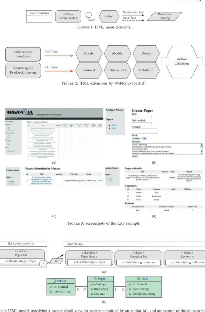
IFML defines the following core elements: View Con-tainer, View Component, Binding, Parameter, Event, Ac-tion, Navigation Flow, and Data Flow. Figure 1 presents their visual concrete syntax.
The main element is the View Container that specifies an interface view and its composition. This element may rep-resent, for instance, a window in a desktop application or a web page in a web application. View Container elements can be nested or contain View Component elements to define richer front-ends. Nested View Containers usually represent panels or tabs in the interface, which could be shown si-multaneously or mutually excluded ([XOR] tag). View Components represent front-end elements to display con-tent or data input. For example, a web form, a listing of objects, or a detail view of a data object are all View Components. Additionally, Data Binding elements link the displayed content to its corresponding data entity of the domain model, which is represented by a class diagram, an entity relationship diagram, or an ontology. Moreover, parameters allow the definition of filters over the displayed content.
Event elements represent the dynamic front-end behav-iour, e.g., the events triggered by the user or the system itself. For example, a user may trigger an event when clicking a menu item. They are commonly associated with View Containers and Components. Furthermore, they may be specialized to represent customized events, e.g., multiselection in a list of elements or form submission.
Action elements represent the business logic from an abstract point of view. They may reference behaviour models (UML activity diagrams, UML sequence diagrams, BPMN diagrams, etc.) describing the actual business logic to be performed. In addition, Actions may trigger a different kind of events, called ActionEvents, as the result of business logic computation termination or the occurrence of exceptions. Moreover, Actions may reside on the server or on the client side.
Interaction Flow elements represent a front-end state change. They can be of two different types: navigation flow and data flow. The former represents an input-output de-pendency between two different IFML elements, specifying their execution sequence, normally triggered by an event. Additionally, they may transport data, as parameter binding groups from one IFML element (source) to the other (target). Data flow represents data passing between view components or actions as a consequence of a previous user interaction.
IFML was designed to be easily extended so that different domains could define its own concepts as extensions of the IFML core elements. This is the case of WebRatio, which
provides a richer set of concepts by extending IFML ele-ments. In this work, we have used the following WebRatio-specific elements (Figure 2).
3.1. View Component Extensions. (1) Selectors, they fetch
data from a database according to a condition and may output these data to other elements; and (2) Messages, they display feedback information to the user.
3.2. Navigation Flow Extensions. (1) OK/KO flows, they
define the control flow based on the result of an operation execution: success is represented by an OK flow, while fail is depicted by a KO flow.
3.3. Action Extensions. (1) Create, (2) Modify, (3) Delete, (4)
Connect, (5) Disconnect, and (6) IsNotNull. They define common data operations. Moreover, WebRatio provides an additional element extension, called Action Definition, to define operation chains. They define input and output ports (squares in the figure) to pass data in and out.
4. Illustrative Example
In order to illustrate this approach, we use a previous case study named the Conference Review System (CRS) (https:// www.eweb.unex.es/eweb/migraria). CRS is a web applica-tion implemented by two different developer teams of our software laboratory. The first team implemented it using Java Enteprise Edition Platform, while the second team built it by means of WebRatio. This system is based on the case study proposed in the First International Workshop on Web-Oriented Software Technology (http://users.dsic.upv.es/ ∼west/iwwost01/).
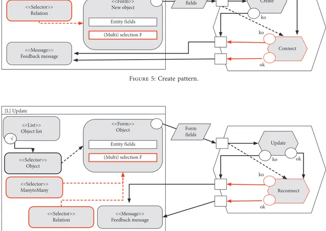
Figure 3 presents four screenshots of this web applica-tion for illustrative purposes: Figure 3(a) is showing a submission (paper) list in the PC member area; Figure 3(b) presents a web form to create a new submission (Paper); and Figures 3(c) and 3(d) implement the master-detail view pattern for submissions (papers) in the author area.
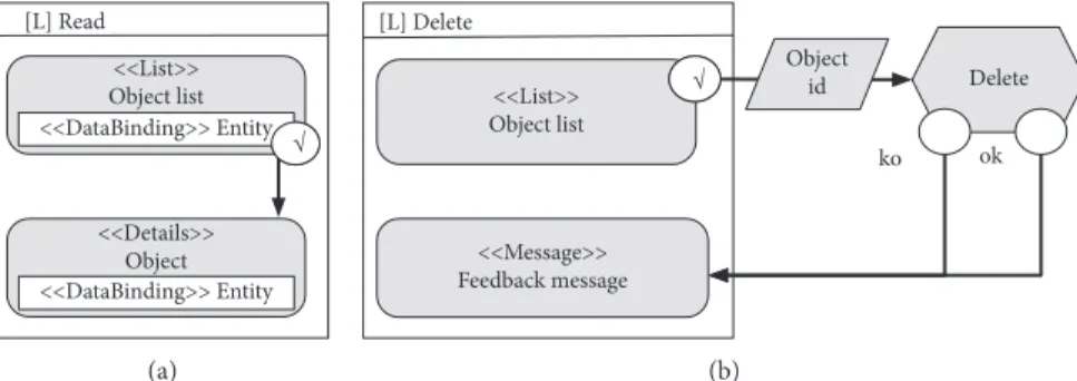
Additionally, Figure 4 displays a partial IFML specifi-cation of the previous web pages. Using a MDWE approach usually implies to work, at least, with two different models: the interaction model (e.g., IFML) and the domain model (e.g., entity relationship diagram). Figure 4(a) shows a simplified IFML specification for the master-detail view represented by web pages 3(c) (master) and 3(d) (detail). Basically, this IFML model contains two different view containers, one for each page. The first one displays a list containing all the submissions of a particular author by means of a list view component bound to the Paper entity. The second one contains three view components, one for each entity to display (1) a detailed view component dis-playing the properties of the selected paper, bound to the Paper entity; (2) a list view component listing the coauthors of that paper, bound to the Author entity; and (3) another list view component listing the available reviews for that paper, bound to the Review entity. Moreover, a navigation
View Container <<View Component>> Event Action Navigation Flow Data Flow Parameter Binding
Figure 1: IFML main elements.
<<Selector>> Condition
<<Message>> Feedback message
OK Flow Create Modify Delete
IsNotNull
Action definition Connect Disconnect
KO Flow
Figure 2: IFML extensions by WebRatio (partial).
(a) (b)
(c) (d)
Figure 3: Screenshots of the CRS example.
[L] Author paper list <<List>>
Paper list <<Details>>Paper details Coauthor list<<List>> Review list<<List>> <<DataBinding>> Paper Id <<DataBinding>> Paper <<DataBinding>> Author <<DataBinding>> Review
Paper details
√
(a)
Subject Paper
id: decimal id: integertitle: string abs: text Track id: decimal name: string discription: string name: string N N 1 N (b)
Figure 4: IFML model specifying a master-detail view for papers submitted by an author (a), and an excerpt of the domain model for example (b).
flow, triggered by the selected user event, transports the id of the paper from one view container to the other, so target view components can be properly populated with the cor-responding data. Note that Author and Review entities are not shown in Figure 4(b) for the sake of brevity. In addition, an excerpt of the domain model for this system is presented in Figure 4(b), which contains a simplified version of the following entities.
4.1. Paper. It represents the submissions in the system and
holds one relationship with each of the other two entities.
4.2. Track. It represents the tracks of a conference and holds
a onetomany relationship with Paper.
4.3. Subject. It represents the submission topics of a
con-ference and holds a manytomany relationship with Paper.
5. IFML Pattern-Based Approach
As commonly stated, design patterns must represent well-known solutions to recurrent problems. In this case, the CRUD patterns presented in this work stem from the vast experience of our industrial partner on the development of web applications using WebRatio for more than 10 years. Nevertheless, our approach fosters the definition and in-stantiation of new patterns in order to maintain a richer pattern repository for a given domain.
Pattern-based development comprises two main stages: (1) pattern definition, when engineers specify in detail the elements and structure of a new pattern and include it in the company repository, and (2) pattern instantiation or ap-plication, when developers select the right pattern from the repository and instantiate it into the web application specification. Following this, we present how patterns are defined in our approach and also how they are applied in the context of the illustrative example.
5.1. Pattern Definition. In order to define IFML patterns, we
follow the approach proposed for object-oriented design patterns, which basically show relationships and interactions between classes or objects, without specifying the final ap-plication classes or objects that are involved. Therefore, IFML patterns are structured IFML model snippets, sharing a common purpose or mission. For example, a Create pattern entails a collection of interconnected IFML elements repre-senting the view containers, view components, events, in-teraction flows, and actions involved in the input of new data by users. Eventually, some of those IFML elements will be parametrized when instantiated to define a final element in the IFML model of the web application under development. The primary parameter for patterns considered in this work is the target data entity (domain model), which rep-resents the data model entity over which the data operation will be performed. Moreover, this entity likely posses at-tributes and relationships with other entities, which may act as additional parameters in other elements of the pattern.
For example, they may be used for data displaying in view containers, data filtering, and data binding specified in navigation flows, among other things. Regarding the latter, the target entity relationships may play a fundamental role in the instantiation of a pattern because additional IFML el-ements may be needed to represent them. As a result, the pattern definition must enable the specification of optional IFML elements, whose instantiation will be triggered by the presence of a particular relationship.
In summary, a pattern is a structure of IFML elements, which will be instantiated by the target data entity. Such entity attributes, and relationships will act as additional parameters for the pattern.
5.1.1. IFML CRUD Patterns. In this section, CRUD patterns
are specified for IFML following the coding style guides of our industrial partner. Note that they are specified from a generic point of view to keep them independent of the app scenario.
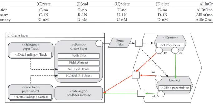
Figure 5 presents the Create pattern. In this case, its main elements are: (1) the Create page as the main view container of the pattern; (2) a view component defining a web form for users to input data, which will contain a field for every entity attribute (instantiation of parameters); (3) an event triggered by users to execute the proper action chain by means of a navigation flow, which contains a data binding group passing the form fields to the action chain; (4) a Create action chain, whose main element is a Create action eventually serializing data into the database; (5) OK and KO navigation flows outgoing from the create action to the (6) message view component, which displays feedback in-formation to users regarding the result of the performed data operation. The sequence of execution in IFML is basically defined by the navigation flows (create, OK and KO flows in the figure). When the user triggers the creation event, all the data operations are executed following the sequence defined by the navigation flows until reaching the message view component, which represents the end of the in-teraction flow for this pattern. So far, we have just pre-sented the mandatory elements of the Create pattern; however, there are also optional elements that need to be dynamically considered when data entity relationships are taken into account. Those optional elements are high-lighted in red in Figure 5 to be easily identifiable. For each relationship, no matter its cardinality, a selector compo-nent and its corresponding selection field inside the form are needed. They represent the data population of a se-lection field according to the entity related to the target data entity by means of the selected relationship. For example, a data entity representing the values of available shipping countries for an online store. Furthermore, for each
manytomany relationship, first, a multiselection field is
included in the form instead of a selection field, and second, a Connect action in the business logic must be executed to properly serialize it into the database.
Figure 6 shows the Update pattern, which presents a structure pretty similar to the previous pattern. Therefore, we are just commenting the differences here. Basically, as
mandatory IFML elements, it includes the following ad-ditional elements: (1) a list view component, which will list all the objects available of the target data entity and will act as the starting point of the data operation; (2) an update event, triggered by the user when clicking on a particular object of the list; (3) a navigation flow propagating the object id to a (4) selector view component, which will fetch the data of the corresponding object from the da-tabase; and (5) a transport flow passing the object data to the web form (view component) to properly populate all the related fields. Additionally, the object id is passed within the data binding group of the navigation flow between the form and the Update action chain. Further-more, optional elements are specified as before when re-lationships are considered.
Figure 7(a) presents the Read pattern. For the sake of brevity and simplicity, we just introduce a simple case of this pattern implementing a master-detail view, without optional elements associated to the presence of relation-ships mainly because there are no important differences between both versions of the pattern. The main elements of this pattern are (1) the Read page as the main view con-tainer of the pattern; (2) a view component (master) de-fining a list with all the objects available of the target data entity and acting as the starting point of the read operation; and (3) a navigation flow propagating the object id to a (4)
view component (detail), which will fetch the data of the corresponding object from the database to display them to the user.
Finally, Figure 7(b) presents the Delete pattern. Again, in this case, there is no need to consider relationships, so no optional elements are specified. Note that the deletion of related objects is commonly defined at data level by means of foreign keys and cascade deletion. The main elements of this pattern are (1) the Delete page as the main view container of the pattern; (2) a view component listing all the objects available of the target data entity and acting as the starting point of the deletion; (3) a navigation flow propagating the object id to a (4) Delete action, which will eventually execute the deletion statement in the database; and (5) OK and KO flows outgoing from the Delete action to the (6) message view component, which displays feedback information to users regarding the result of the data operation.
5.2. Pattern Instantiation. In our approach, the process of
instantiating a pattern entails the following steps: (1) selecting the particular pattern from the repository; (2) identifying the target data entity from the domain model (the data operation will be defined over this entity); (3) indicating the entity attributes to include in the pattern; and finally (5) selecting the entity relationships to consider.
[L] Update <<List>> Object list <<Selector>> Object <<Selector>> ManytoMany <<Selector>> Relation <<Message>> Feedback message Form fields Update Reconnect ok ok ko ko <<Form>> Object Entity fields (Multi) selection F √
Figure 6: Update pattern.
[L] Create <<Selector>> Relation <<Form>> New object Form fields Create ok ok ko ko Connect Entity fields (Multi) selection F <<Message>> Feedback message
Different relationship cardinality may involve some differences among the instantiations of a particular pattern by enabling the instantiation of its optional elements. As a result, we need to consider the following instantiation al-ternatives for every IFML pattern defined: (1) no
relation-ship, just the target data entity; (2) a onetomany relationrelation-ship,
the target data entity holds a 1-N relationship with another data entity and it must be considered when instantiating the pattern; and (3) a manytomany relationship, the target data entity holds a N-N relationship with another data entity, and it must be considered when instantiating the pattern. In a complex scenario, pattern instantiations have to deal with target data entities holding multiple relationships that must be included.
According to the previous relationship choices, Table 1 shows the instantiation alternatives (cases) for the CRUD patterns considered in this work. An additional pattern (AllInOne), representing an optimal specification of all the CRUD operations on a particular data entity, is included in the table but not explained in this work for the sake of brevity.
5.2.1. Pattern Instantiation Example. For illustrative
pur-poses, we have decided to exemplify the instantiation of the Create pattern over the data entity Paper from the Con-ference Review System. We model the web page shown in Figure 3(b), which represents precisely this data operation. A new submission (Paper) requires to consider data re-lationships with Track and Subject entities because each new submission must indicate a target track and, at least, one conference topic. As a result, this example is considering two relationships with different cardinality (onetomany and
manytomany) when instantiating the pattern. So two
dif-ferent instantiation cases are exemplified at the same time: C-1N and C-nM, according to Table 1.
After pattern instantiation, the final IFML snippet, shown in Figure 8, is automatically included into the model of the application. Concretely, the figure shows all the mandatory elements, which are properly instantiated with the corresponding data entity. Those elements are (1) the Create Paper page as main view container; (2) the form view component containing fields for each Paper attribute (title and abstract); (3) the submit event and its navigation flow associated with the form fields as a data binding group; (4) the Create action, taking as input the output of
the form and instantiated with the data entity Paper; and finally (5) the OK/KO flows departing from the action and ending into the message view component. Note that the view containers and components accurately represent the HTML elements identifiable in the web form of Figure 3(b). Now we focus on the optional elements of the pattern. Two selector view components are instantiated inside the page, one for each relationship considered: paperTrack and paperSubject. Those selectors are bound to their corresponding data entity and provide the form with the necessary data to populate the additional selection fields with the tracks available and the subjects considered. Finally, an additional action, connect, needs to be in-stantiated to properly store the subjects selected in the web form for the new paper. The presence of this new action makes necessary to deviate the OK flow departing from the create action because the successful execution sequence must include that connect action. Furthermore, a data flow is defined between the input port of the action chain and the new action to transport the data from the web form to the connect action.
Table 2 shows the number of IFML elements, grouped by type, necessary for the instantiation of this CRUD pattern in this particular case (just C-nM). An IFML modeler needs to use 15 different IFML elements to specify a create operation over a data entity and the involved interactions. Furthermore, IFML elements have been classified into three main groups: flows, units, and bind-ings. These groups have been defined based on the expected effort made by a developer to specify elements of a concrete group assisted by using the WebRatio tool. In other words, the elements that require a similar effort in their specifi-cation are classified into the same group. They will also be considered in the validation of the approach. It should be noticed that OKLink and KOLink flows are never con-sidered as binding holders because they just imply a single message passing.
According to the previous classification, Table 3 sum-marizes the number of IFML elements needed for the in-stantiation of a Create pattern over a target entity with a
manytomany relationship.
5.2.2. IFML Elements Generated for Each Instantiation.
The other IFML patterns for CRUD operations can be in-stantiated following a similar process. Although concrete
[L] Read <<List>> Object list <<Details>> Object <<DataBinding>> Entity <<DataBinding>> Entity √ (a) [L] Delete Object id Delete ko ok <<Message>> Feedback message <<List>> Object list √ (b)
details of their application are not discussed in this work, Table 4 presents a summary of the total number of IFML elements generated for the application of each CRUD pattern in every instantiation case considered. As a main conclusion, a developer has to use, connect, and configure more than 18 IFML elements in average to specify a CRUD operation over a data entity of the domain model. Note that Read and Delete patterns are not considering relationships herein, so their numbers are the same in the three different instantiation cases contemplated. Those values correspond to the no-relation case.
6. Tool Support
Along this work, we have developed two different versions of the tool supporting the pattern-based IFML specification of CRUD operations. This tool is named AutoCRUD, and its last version was published in [15], including its source code, user, and developer manuals. In this section, for the sake of completeness, we briefly illustrate the main use case of our tool.
AutoCRUD mainly plays the role of a scaffolding tool for WebRatio by providing engineers with a pattern repository of the most frequently used IFML snippets for their projects (pattern definition). This tool is open to extension; hence, its pattern repository may be conveniently customized by every development team to specifically tailor it to its own ne-cessities and styles.
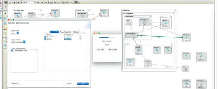
Once IFML patterns are defined and stored into the repository, our pattern-based development approach may be easily applied by instantiating patterns on concrete target data entities, further parametrized by their attributes and relationships. Figure 9 illustrates both the instantiation of a particular pattern (left side) and the generation of its final IFML specification in the project under development (right side).
Regarding the instantiation step, a particular wizard dialogue (left side) provides engineers with all the available patterns to apply (select pattern drop-down list), together with all the data entities of the domain model (select entity drop-down list). Moreover, relationship and attribute lists are dynamically updated according to the selected data entity. Therefore, engineers have in a single place all the data needed to perform a proper pattern instantiation in a matter of seconds. Additionally, this dialogue has a button to access the registry functionality, which maintains a detailed account of all the IFML elements created by the tool.
Regarding the IFML generation step, Figure 9 (right side) presents the generation of the IFML specification for the pattern defining all the CRUD operations for a data entity at the same time (AllInOne). In this case, the dialogue in the middle allows engineers to select between two dif-ferent operation modes: (1) step-by-step mode, which in-teractively generates IFML elements one by one (useful for educational purposes), or (2) fast forward mode, which generates the whole final IFML snippet in just one step (useful for production).
7. Industrial Validation
With the intention of assessing the utility of our approach, this section shows the results of its application to different projects developed by our industrial partner, Homeria SL [23]. The main goal of this evaluation is to analyze the impact of including our pattern-based approach and its supporting tool into the company development process in terms of their potential reduction in production costs.
Homeria is an official partner of WebRatio (http:// www.webratio.com/site/content/es/partners) with a large team of developers certified in web application
[L] Create Paper <<Selector>> paper Track <<Selector>> paperSubject <<Message>> Feedback message <<DataBinding>> Subject <<Form>> Create Paper <<Create>> Connect <<DB>> Paper ok ok ko ko <<DB>> paperSubject Form fields Field: Title Field: Abstract Sel. Field: Track MultiSel. F.: Subject <<DataBinding>> Track
Figure 8: Create pattern instantiation with two relationships: a onetomany (Track) and a manytomany (Subject). Table 1: CRUD patterns’ instantiation cases.
(C)reate (R)ead (U)pdate (D)elete AllInOne
No relation C-no R-no U-no D-no AllInOne-no
Onetomany C-1N R-1N U-1N D-1N AllInOne-1N
T able 2: IFML elements for the C-nM case. Flows Units Bindings T otal Navigation flow Data flow OKLink KOLink Page Index Data Form Selector Message Content Create Modify Delete Connect Disconnect IsNotNull Binding C- nM 1 2 2 2 1 1 1 1 1 1 3 15
construction with WebRatio, IFML, and data-driven methodologies. In the last 9 years, this company, which relies on an important client portfolio, has carried out more than 100 projects.
In this analysis, we have considered the development time as the production cost unit. Therefore, shorter devel-opment times mean lower production costs. In order to obtain relevant base time measurements, the next procedure has been followed:
(i) A group of developers was selected for the analysis. Concretely, 10 members were chosen from those with higher experience in WebRatio development. Hence, all the developers had a similar experience in developing data-intensive web applications with such technology.
(ii) That group of developers was responsible for cre-ating all the CRUD operations in the projects they were working at the moment of performing this study. They specified a variety of CRUD operations over different data entities in dissimilar situations. Therefore, all the possibilities considered in our approach were covered.
(iii) We measured the time spent on defining the whole collection of IFML elements needed to specify each CRUD operation. For this purpose, the time taken by each developer to specify each operation was recorded in a shared timesheet. Finally, the average time for each operation was calculated.
As aforementioned, regarding similar development times, IFML elements were classified into three main groups: flows, units, and bindings. The average development time for the different groups were obtained, which are shown in Table 5. They constitute a reference for the measurements performed during the study. This table also presents the standard deviation in each case. Note that insignificant deviations are obtained for the manual measurements, mainly due to the homogeneous expertise of the selected developers. These values are not significant compared to the average time assessed. Note that, although these values could vary in terms of developers’ expertise, this study could be replicated in other companies just by adapting the devel-opment base time values according to the expertise of a particular team (just repeating the measurement for each CRUD operation).
According to the values shown in Table 5, Table 6 presents the costs involved in the manual specification of each CRUD operation definition case (considering data entity relationships). In order to be able to compare manual to tool-aided development times, Table 6 also shows how long (on average) it takes a developer to specify each case for the CRUD operations using AutoCRUD. Note that we are not considering here the time spent on the automatic
generation of the final code because it is not significant enough.
Once the base time measurements were obtained, we analyzed 6 different projects previously developed by the company, whose source models were available. For this purpose, a quantitative analysis was carried out where the IFML elements needed for CRUD operations’ specification were identified.
As an example of the results, Table 7 shows for each project: (1) its size; (2) the amount of CRUD operations,
organized by cases; (3) the total number of CRUD operations; (4) the total number of data entities in the data model; (5) the total number of IFML elements used to specify all the CRUD operations (classified as flows, units, and bindings); and (6) the total time (in hours) dedicated to the project (based on
timesheets used by the developers). Based on the number of CRUD cases (instantiation cases according to data entity relationships, Table 1) in each project (row (2)) and the time spent on specifying each case (shown in Table 6), the total time needed for manually implementing these operations has been calculated for each project (row (7)). Based on rows
(6) and (7), the percentage of time dedicated to the CRUD
operations for each project is shown in row (8). Likewise, considering the time spent on specifying each CRUD op-eration with our tool (last column in Table 6), the time taken to define all the CRUD operations with AutoCRUD for each project has been calculated (row (9)). Finally, the table shows the difference (row (10)) between both costs (manually) vs. tool aided (showing the benefits in terms of hours and percentage).
As shown in Table 7, the development time reduction obtained by using our tool is above 95% of the total time dedicated to CRUD operations in all the projects. These results show a clear evidence of the significant productivity improvement provided by our approach and tool presented here since they practically eliminate the time dedicated to CRUD operations specification from the projects. Moreover, Table 7 shows also some evidence about a possible corre-lation between the benefit obtained and the project size. In other words, the larger the project, the more significant the productivity improvement obtained. As an example, a 99.88% time reduction in CRUD specification for the largest project was achieved.
Additionally, these results should also be considered regarding the percentage of time dedicated to CRUD specification in each project. Observe that, in the projects analyzed, these percentages range from 6.14% to 9.69% of the total development time (row (8) in Table 7). This means that, for instance, our tool-aided approach is able to achieve a 10% reduction in the total development time for the largest project. Moreover, such result becomes even more relevant considering the total development time involves many other activities, such as user interface design or scripting imple-mentation. Furthermore, according developers’ timesheets, the percentage of time dedicated to IFML specification in each project is presented in Figure 10 (horizontal axis). It also shows the percentage of the IFML specification time dedicated to CRUD operations (vertical axis) so that the reduction in the time dedicated to IFML in each project has
Table 3: Aggregated number of IFML elements for the C-nM case.
Flows Units Bindings
T able 4: Number of IFML elements for all possible instantiations. Navigation flow Data flow OKLink KOLink Page Index Data Form Selector Message Content Create Modify Delete Connect Disconnect IsNotNull Binding T otal C-no 1 0 1 1 1 0 0 1 0 1 0 1 0 0 0 0 0 1 8 R-no 1 0 0 0 1 1 1 0 0 0 0 0 0 0 0 0 0 1 5 U-no 2 1 1 1 1 1 0 1 1 1 0 0 1 0 0 0 0 3 14 D-no 1 0 1 1 1 1 0 0 0 1 0 0 0 1 0 0 0 1 8 All- no 5 3 4 4 5 1 1 1 1 1 1 2 0 1 0 0 1 6 37 C-1N 1 1 1 1 1 0 0 1 1 1 0 1 0 0 0 0 0 2 11 R-1N 1 0 0 0 1 1 1 0 0 0 0 0 0 0 0 0 0 1 5 U-1N 2 2 1 1 1 1 0 1 1 1 0 0 1 0 0 0 0 4 18 D-1N 1 0 1 1 1 1 0 0 0 1 0 0 0 1 0 0 0 1 8 All- 1N 7 4 4 4 5 1 1 1 2 1 1 2 0 1 0 0 1 9 44 C- nM 1 2 2 2 1 0 0 1 1 1 0 1 0 0 1 0 0 3 17 R- nM 1 0 0 0 1 1 1 0 0 0 0 0 0 0 0 0 0 1 5 U- nM 2 5 3 3 1 1 0 1 3 1 0 0 1 0 1 1 0 7 30 D- nM 1 0 1 1 1 1 0 0 0 1 0 0 0 1 0 0 0 1 8 All- nM 7 8 6 6 5 1 1 1 2 1 1 2 0 1 1 1 1 13 58
been calculated. This reduction varies from 14.99% (P2) to 28.15% (P6). As a result, considering that the time dedicated to CRUD specification is almost completely eliminated, a 19.75% (mean) reduction in the time dedicated to IFML specification is eventually achieved in these projects. Finally, as Figure 10 clearly illustrates, there seem to be no
correlation between the size of the project and the final time reduction achieved.
8. Conclusions
This paper has presented a pattern-based approach to reduce web application development effort when using IFML as specification language. The definition and instantiation of IFML patterns have been introduced with detail and ex-emplified by specifying common CRUD operations as IFML patterns. Those definitions have been developed in collab-oration with an industrial partner to properly derive them from experience. However, they are not mandatory. Therefore, every company can define them according to its own experience and style. Additionally, our approach fosters the definition and instantiation of new patterns in order to maintain a richer pattern repository for a given domain. Furthermore, we have developed a supporting tool to simplify and automate pattern instantiation and operation. The tool has been developed as a WebRatio plug-in by explicit requirement of our industrial partner so that it can be easily integrated into its development process. Finally, we presented the results of applying our approach (and tool) to real life projects developed by our industrial partner. As main benefits, we have observed the following: (1) a clear reduction of the time spent in repetitive tasks (specification of CRUD operations); (2) a significant decrement of errors due to redundant IFML specifications; and (3) a growing consistency across projects regarding CRUD modeling, which makes applications more regular and thus more usable.
As future work, we plan to follow several research lines. We want to define IFML patterns to automate other repetitive modeling activities in IFML, probably focusing on specific domains, e.g., mobile applications. We are also working on the definition of some heuristics to guide an algorithm on the automatic generation of the most likely useful CRUD operations for every data entity
Figure 9: Tool screenshot.
Table 5: Developer time average (secs) per group of IFML elements.
Group Flows Units Bindings
Dev. time (secs) 24 112 66
Standard deviation (S) 1.55 4.22 2.83
Table 6: Development time (secs) for the specification of every CRUD case: manually and AutoCRUD supported.
Flows Units Bindings Manual dev.
time (secs)
AutoCRUD dev. time (secs)
C-no 3 4 1 586 1 R-no 1 3 1 426 1 U-no 5 6 3 990 1 D-no 3 4 1 586 1 All-no 16 19 6 2908 2 Total-no 28 36 12 5496 6 C-1N 4 5 2 788 2 R-1N 1 3 1 426 1 U-1N 6 7 4 426 2 D-1N 3 4 1 1192 1 All-1N 19 16 9 2842 3 Total-1N 33 35 17 5674 9 C-nM 7 5 3 926 3 R-nM 1 3 1 426 1 U-nM 13 10 7 1894 3 D-nM 3 4 1 586 1 All-nM 27 18 13 3522 5 Total-nM 51 40 25 7354 13
Table 7: Results of the 6 projects under evaluation. Projects
P1 P2 P3 P4 P5 P6
(1) Size
Big Medium Medium Medium Small Small
(2) Different CRUD cases
C-no 115 8 5 3 2 2 R-no 107 9 4 3 1 1 U-no 116 7 5 4 2 1 D-no 112 7 5 5 1 1 All-no 116 9 5 3 2 2 C-1N 97 5 4 4 2 1 R-1N 94 7 4 3 2 1 U-1N 92 4 4 3 2 1 D-1N 95 6 3 3 1 1 All-1N 97 10 4 4 2 2 C-nM 26 6 3 4 3 3 R-nM 42 8 2 2 2 2 U-nM 42 9 6 4 3 2 D-nM 24 6 3 3 1 1 All-nM 83 7 6 5 4 2
(3) Total CRUD operations
1258 108 63 63 38 33
(4) Entities in the domain model
193 84 36 27 14 10
(5) Total IFML units
Total flows 11259 874 512 404 224 177
Total units 11285 848 533 391 222 168
Total bindings 5387 414 250 194 108 109
(6) Project total time
Hours 5380 650 350 230 125 80
(7) CRUD operation cost (manually)
Secs 1876777 143848 77388 65812 34258 28382
Hours 521.33 39.96 21.50 18.28 9.52 7.88
(8) Time dedicated to CRUD
% 9.69 6.15 6.14 7.95 7.61 9.85
(9) CRUD operations cost (tool aided)
Secs 2225 1370 1339 1330 1317 1307
Hours 0.62 0.38 0.37 0.37 0.37 0.36
(10) Time reduction in CRUD definition (manual-tool aided)
Hours 520.71 39.58 21.12 17.91 9.15 7.52 % 99.88 99.05 98.27 97.98 96.16 95.39 T ime (%) CR UD sp ecif ica tio n in IFML 30 25 P6 P5 P4 P3 P2 P1 20 15 10 35 40
Time (%) for IFML specification
50 45
given a domain model and a profile of the final appli-cation. In parallel, we plan to extend this algorithmic approach to automatically discover and register patterns from preexisting IFML models to improve their maintenance.
Data Availability
All the data used in the validation section are attached to the article as a supplementary file in order to allow researchers to verify the results, replicate the analysis, and conduct sec-ondary analyses.
Conflicts of Interest
All the authors confirm that the mentioned received funding did not lead to any conflicts of interest regarding the publication of this manuscript.
Acknowledgments
The authors wish to acknowledge the collaborative funding support from (i) POCTEP 4IE project (0045-4IE-4-P) and (ii) Consejer´ıa de Econom´ıa e Infraestructuras/Junta de Extremadura (Spain)-European Regional Development Fund (ERDF) projects (GR18112 and IB16055). The authors also wish to acknowledge the valuable contribution of Homeria as the industrial partner who participated in the development of the tool and its validation.
Supplementary Materials
Herewith this document, a spreadsheet with all the data needed to perform our validation has been included. Concretely, this file contains 4 different sheets, which are next described using their names as identifiers. Sheet 1 contains the data to populate Tables 5 and 6 of this paper. Such data are organized into three different tables: Table 1 shows the time spent by each developer on manually specifying each IFML element (summarized in Table 5 of the paper). Table 2 groups four different tables presenting the number of entities involved in the specification of each CRUD realization case, considering data entity relation-ships. This information is used in Table 6 of the paper. Table 3 just shows the mean times of manual development, which we used to calculate Table 2 (last column) of that sheet. Sheet 2 contains two tables necessary to create part of Table 7 in the paper. Concretely, Table 1 provides the values shown in its row 2, while Table 2 contains the base mea-surements to compute the values shown in its row 9 (CRUD operation costs (tool aided)). Sheet 3 contains data about CRUD operation cost for each project considered, useful for Table 7 in the paper. Table 1 shows manual specification cost (time) whilst Table 2 presents tool-aided cost (rows 7 and 9, respectively). Sheet 4 also contains data for Table 7 and Figure 10 in the paper. In particular, Table 1 presents the values needed for rows 6 to 10, while Table 2 shows the data to calculate the percentage of time dedicated to CRUD specification with respect to both the total project time and
the time dedicated to IFML specification for each project (row 8). (Supplementary Materials)
References
[1] N. Koch, S. Meli´a-Beigbeder, N. Moreno-Vergara et al., “Model-driven web engineering,” Upgrade-Nov´atica
Jour-nal, Council of European Professional Informatics Societies (CEPIS), vol. 9, no. 2, pp. 40–45, 2008, in English and
Spanish.
[2] G. Rossi, O. Pastor, D. Schwabe, and L. Olsina, Web
Engineering: Modelling and Implementing Web Applica-tions, Springer Science & Business Media, Berlin, Germany,
2007.
[3] P. Vuorimaa, M. Laine, E. Litvinova, and D. Shestakov, “Leveraging declarative languages in web application development,” World Wide Web, vol. 19, no. 4, pp. 519–543, 2016.
[4] M. Brambilla and P. Fraternali, Interaction Flow Modeling
Language: Model–Driven UI Engineering of Web and Mobile Apps with IFML, Elsevier Science, Amsterdam, Netherlands,
2014.
[5] S. Casteleyn, I. Garrig´os, and J.-N. Maz´on, “Ten years of rich internet applications: a systematic mapping study, and be-yond,” ACM Transactions on the Web (TWEB), vol. 8, no. 3, pp. 1–46, 2014.
[6] G. Toffetti, S. Comai, J. C. Preciado, and M. Linaje, “State-of-the art and trends in “State-of-the systematic development of rich internet applications,” Journal of Web Engineering, vol. 10, pp. 70–86, 2011.
[7] M. Fowler, Patterns of Enterprise Application Architecture, Addison-Wesley Longman Publishing Co., Inc., Boston, MA, USA, 2002.
[8] Ruby on Rails, April 2019, Available at: https://rubyonrails. org/.
[9] Djangoproject.com, The web framework for perfectionists with deadline|django, April 2019, Available at: https://www. djangoproject.com/.
[10] Castleproject.org, Monorail|castle project, April 2019, Available at: https://www.castleproject.org/projects/monorail/.
[11] funkreich.de, T Catalyst|perl MVC web application frame-work, Catalyst framework.org, April 2019, Available at: http:// www.catalystframework.org/.
[12] S. Mbarki and M. Erramdani, “Toward automatic generation of mvc2 web applications,” INFOCOMP, vol. 7, pp. 84–91, 2008.
[13] P. E. Papotti, A. F. Do Prado, W. L. de Souza, C. E. Cirilo, and L. F. Pires, “A quantitative analysis of model-driven code generation through software experimentation,” in
Proceedings of the International Conference on Advanced Information Systems Engineering, pp. 321–337, Valencia,
Spain, June 2013.
[14] R. Rodriguez-Echeverria, J. M. Conejero, J. C. Preciado, and F. Sanchez-Figueroa, “AutoCRUD-automating IFML spec-ification of CRUD operations,” in Proceedings of the 12th
International Conference on Web Information Systems and Technologies, vol. 1, pp. 307–314, Rome, Italy, December
2016.
[15] R. Rodriguez-Echeverria, J. C. Preciado, J. Sierra,
J. M. Conejero, and F. Sanchez-Figueroa, “AutoCRUD: au-tomatic generation of CRUD specifications in interaction flow modelling language,” Science of Computer Programming, vol. 168, pp. 165–168, 2018.
[16] A. Fatolahi and S. S. Some, “Assessing a model-driven web-application engineering approach,” Journal of Software
En-gineering and Applications, vol. 7, no. 5, pp. 360–370, 2014.
[17] Y. Mart´ınez, C. Cachero, and S. Meli´a, “Empirical study on the maintainability of web applications: model-driven engineer-ing vs code-centric,” Empirical Software Engineerengineer-ing, vol. 19, no. 6, pp. 1887–1920, 2014.
[18] G. Jaime, P. Sandy, D. Oscar et al., “A model-driven devel-opment for GWT-based rich internet applications with OOH4RIA,” in Proceedings of the Eighth International
Con-ference on Web Engineering, vol. 13–23, New York, NY, USA,
July 2008.
[19] Y. Mart´ınez, C. Cachero, M. Matera, S. Abrahao, and S. Luj´an, “Impact of MDE approaches on the maintainability of web applications: an experimental evaluation,” in Proceedings of
the International Conference on Conceptual Modeling,
vol. 233–246, Brussels, Belgium, November 2011.
[20] S. Ceri, A. Bongio, P. Fraternali, M. Brambilla, S. Comai, and M. Matera, “Designing data-intensive web applications,” in
Morgan Kaufmann Series in Data Management Systems,
Morgan Kaufmann Publishers, Burlington, MA, USA, 2003. [21] S. Ceri, P. Fraternali, and A. Bongio, “Web modeling language (WebML): a Modeling Language for designing web sites,”
Computer Networks, vol. 33, no. 1–6, pp. 137–157, 2000.
[22] Grocerycrud.com, Grocery CRUD|auto PHP codeigniter CRUD, April 2019, Available at: https://www.grocerycrud. com.
[23] Homeria.com, HOMERIA -open solutions, April 2019, Available at: https://www.homeria.com.
Computer Games Technology International Journal of Hindawi www.hindawi.com Volume 2018 Hindawi www.hindawi.com Journal of
Engineering
Volume 2018 Advances inFuzzy
Systems
Hindawi www.hindawi.com Volume 2018 International Journal of Reconfigurable Computing Hindawi www.hindawi.com Volume 2018 Hindawi www.hindawi.com Volume 2018Applied
Computational
Intelligence and Soft
Computing
Advances inArtificial
Intelligence
Hindawi www.hindawi.com Volume 2018 Hindawi www.hindawi.com Volume 2018Civil Engineering
Advances inHindawi
www.hindawi.com Volume 2018
Electrical and Computer Engineering Journal of Journal of Computer Networks and Communications Hindawi www.hindawi.com Volume 2018 Hindawi www.hindawi.com Volume 2018
Multimedia
International Journal ofBiomedical Imaging
Hindawi www.hindawi.com Volume 2018 Hindawi www.hindawi.com Volume 2018 Engineering Mathematics International Journal ofRobotics
Journal of Hindawiwww.hindawi.com Volume 2018 Hindawiwww.hindawi.com Volume 2018
Computational Intelligence and Neuroscience Hindawi www.hindawi.com Volume 2018 Mathematical Problems in Engineering Modelling & Simulation in Engineering Hindawi www.hindawi.com Volume 2018
Hindawi Publishing Corporation
http://www.hindawi.com Volume 2013 Hindawi www.hindawi.com