Instituto de Geociências - IG
Pós-Graduação em Geociências Aplicadas
Alexandre de Amorim Teixeira
Ottocodificação Estendida e Inteligência Hidrográfica em
Banco de Dados Geográficos
Tese de Doutorado Nº 02
Instituto de Geociências - IG
Pós-Graduação em Geociências Aplicadas
Alexandre de Amorim Teixeira
Ottocodificação Estendida e Inteligência Hidrográfica em
Banco de Dados Geográficos
Tese de Doutorado Nº 02
Tese apresentada à Banca Examinadora do Instituto de Geociências
como exigência final para obtenção do título de Doutor em Geociências Aplicadas
Ottocodificação Estendida e Inteligência Hidrográfica em Banco de
Dados Geográficos
Alexandre de Amorim Teixeira
BANCA EXAMINADORA
___________________________________
Prof. Dra. Adalene Moreira Silva
–
IG/UnB
___________________________________
Prof. Dr. Fernando F. Pruski - UFV
___________________________________
Prof. Dr. Clodoveu Davis Jr - UFMG
___________________________________
Prof. Dra. Noris Costa Diniz - IG-UnB
AGRADECIMENTOS
RESUMO
A presente tese apresenta um aprimoramento do sistema de codificação de bacias hidrográficas baseada na proposta de Pfafstetter, mas que resolve as principais limitações da representação de uma rede hidrográfica unifilar como confluências múltiplas, foz em delta, enlaces, entre outras. Além disso, o presente trabalho apresenta um novo modelo conceitual do pacote de hidrografia das Especificações Técnicas para
Aquisição e Estruturação de Dados Geoespaciais Digitais Vetoriais
ABSTRACT
SUMÁRIO
CAPÍTULO 1 – INTRODUÇÃO ... 01
1.1 Definição do Problema ... 02
1.2 Justificativa do Trabalho ... 05
1.3 Objetivos ... 06
1.3.1 Objetivo Geral ... 06
1.3.2 Objetivos Específicos ... 07
1.4 Área de Estudo ... 07
1.5 Origem dos Dados e Informações... 08
1.6 Modelo Analítico ... 09
CAPÍTULO 2 - BASIN CODING SYSTEM BASED ON PFAFSTETTER’S PROPOSAL ... 10
2.1 Introduction ... 10
2.2 Basin Coding Systems ... 12
2.3 Limitations of Pfafstetter Basin Coding System ... 22
2.4 Improvements on Pfafstetter Basin Coding System ... 28
2.4.1 Multiple Confluences ... 30
2.4.2 Cycles or Loops ... 35
2.4.3 Sink/Spillway ... 37
2.4.4 Water Masses ... 38
2.5 Conclusions and Recommendations ... 39
CAPÍTULO 3 - HYDROGRAPHIC MODELING IN SPATIAL DATABASE MANAGEMENT SYSTEM ... 40
3.1 Introduction ... 40
3.2 National Information System on Water Resources in Brazil – SNIRH... 41
3.3 Geographic Database Management System – SGBDG ... 41
3.4 National Spatial Data Infrastructure in Brazil – INDE ... 42
3.4.1 Brazilian Background ... 42
3.4.2 The OMT-G data model ... 44
3.4.3 Representation of Spatial Relationships in Class Diagrams ... 44
3.4.4 Structure of Digital Geospatial Data Vector – EDGV ... 53
3.4.4.1 EDGV Hydrographic Package ... 53
3.5 Proposed Conceptual Model of Geographic Database for Hydrography ... 53
3.5.1 Class Diagrams ... 54
3.5.2 Transformation Diagrams ... 58
3.5.3 Integrity Constraints ... 59
3.5.3.1 Geometric Constraints on Related Geometric objects ... 60
3.5.3.2 User-Defined Integrity Constraints ... 61
3.5.3.3 Integrity Constraints Obtained From Relationships ... 61
3.5.3.3.1 Basic Spatial Relationships ... 61
3.6 Implementation of Hydrographic Modeling into Spatial Database
Management System ... 65
3.6.1 Mapping OMT-G conceptual schemes for implementation schemes ... 65
3.6.1.1 Mapping of geo-referenced and conventional classes ... 65
3.6.1.2 Mapping simple associations ... 66
3.6.1.3 Mapping spatial relationships ... 67
3.6.1.4 Mapping of generalizations, specializations and spatial aggregations ... 68
3.7 Conclusions and Recommendations ... 68
CAPÍTULO 4 - OBJETOS HIDROGRÁFICOS EM SISTEMA GERENCIADOR DE BANCO DE DADOS GEOGRÁFICOS ... 70
4.1 Introdução ... 70
4.2 pgHydro: Objetos Hidrográficos em Sistema Gerenciador de Banco de Dados Geográficos PostGIS/PostgreSQL ... 71
4.3 Arquitetura Tecnológica ... 71
4.4 Modelagem Conceitual e Implementação Física do Banco de Dados Geográficos ... 73
4.5 Construção de uma Base Hidrográfica em Banco de Dados Geográficos ... 77
4.5.1 Inserção de Dados ... 78
4.5.2 Consistência da Rede Hidrográfica ... 79
4.5.2.1 Rede de Drenagem com Objetos Geométricos Únicos ... 80
4.5.2.2 Transformação da Rede Hidrográfica para Objetos Geométricos Únicos ... 80
4.5.2.3 Rede de Drenagem com Vetor Simples ou Vetor Válido ... 80
4.5.2.4 Rede de Drenagem sem Auto Sobreposição ... 80
4.5.2.5 Rede Hidrográfica sem Enlace (Loop) ... 81
4.5.2.6 Junção de Trechos de Drenagem ... 81
4.5.2.7 Gerar a Topologia da Rede de Drenagem ... 81
4.5.2.8 Determinar a direção de vetorização dos Trechos de Drenagem e Checar se a Rede de Drenagem está Conexa ... 82
4.5.2.9 Gerar a Valência dos Nós da Rede de Drenagem ... 82
4.5.2.10 Calcular o Valor de Comprimento dos Trechos da Rede de Drenagem ... 82
4.5.3 Verificação de Consistência das Áreas de Contribuição Hidrográfica ... 83
4.5.3.1 Áreas de Contribuição Hidrográfica com Objetos Geométricos Únicos .... 83
4.5.3.2 Áreas de Contribuição Hidrográfica sem Auto Sobreposição... 84
4.5.3.3 Áreas de Contribuição Hidrográfica sem Duplicação... 84
4.5.3.4 Áreas de Contribuição Hidrográfica com Vetor Simples ... 84
4.5.3.5 Áreas de Contribuição Hidrográfica com Vetor Válido ... 84
4.5.3.6 Calcular o Valor de Área das Áreas de Contribuição Hidrográfica ... 84
4.5.4 Verificação de Consistência das Áreas de Contribuição Hidrográfica com os Trechos da Rede de Drenagem ... 84
4.5.4.1 Carregar os Dados de Trecho de Drenagem com Sentido de Fluxo Correto ... 86
4.5.5 Gerar a Codificação de Bacias Hidrográficas de Pfafstetter ... 87
4.5.5.1 Função Consulta Trechos a Jusante Até a Foz da Bacia a Partir de Um Trecho ... 88
4.5.5.3 Função Distancia a Foz da Bacia a Partir da Foz de Um Trecho ... 88
4.5.5.4 Função Distancia à Foz da Bacia a Partir da Foz de Um Trecho da Rede de Drenagem Considerando a Linha de Costa ... 88
4.5.5.5 Função Consulta Trechos a Montante a Partir do Trecho ... 88
4.5.5.6 Função Cálculo de Área a Montante a Partir do Trecho da Drenagem .... 89
4.5.5.7 Função Consulta Seleção do Trecho Imediatamente a Jusante do Trecho ... 89
4.5.5.8 Função Consulta Seleção do Trecho Imediatamente a Montante da Foz do Trecho ... 89
4.5.5.9 Função Seleção de Trechos do Curso D’água Principal a Partir do Trecho que Contem a Foz ... 89
4.5.5.10 Função Seleção dos Trechos mais a Jusante dos Quatro Cursos D’água Principais que Desaguam No Curso D’água Principal da Bacia ... 89
4.5.5.11 Função Codificação de Bacia Continental de Pfafstetter ... 90
4.5.5.12 Função Codificação de Bacias Continentais de Pfafstetter ... 90
4.5.5.13 Função Codificação Final de Bacias Continentais de Pfafstetter ... 90
4.5.6 Geração das Informações Hidrográficas Finais ... 91
4.5.6.1 Inserção do código de bacia na tabela com as áreas de contribuição hidrográfica ‘geoft_areacontribuicaohidrografica’ ... 92
4.5.6.2 Inserção de dados na tabela de Cursos D’Água ‘geoft_cursodagua’ ... 92
4.5.6.3 Inserção dos dados da coluna da chave estrangeira da tabela ‘geoft_cursodagua’ na tabela ‘geoft_trechodrenagem’... 93
4.5.6.4 Inserção dos níveis de codificação de bacia e de curso d’água ... 93
4.5.6.5 Inserção da Ordem de Curso D’água ... 93
4.5.6.6 Inserção de dados na tabela ‘geoft_baciahidrografica’ ... 94
4.5.6.7 Inserção de dados na tabela ‘geoft_cursodaguaprincipal’ ... 94
4.5.6.8 Atualização de dados na tabela ‘geoft_pontodrenagem’ ... 94
4.5.6.9 Inserção de dados na tabela ‘geoft_pontoiniciodrenagem’ ... 95
4.5.6.10 Inserção de dados na tabela ‘geoft_pontofimdrenagem’ ... 95
4.5.6.11 Inserção de dados na tabela ‘geoft_confluencia’ ... 95
4.5.6.12 Inserção dos relacionamentos topológicos ... 95
4.6 Vantagens Computacionais do Sistema de Codificação de Bacias Hidrográficas de Pfafstetter ... 95
4.7 Estudo de Caso ... 99
4.8 Conclusões e Recomendações ... 103
CAPÍTULO 5 – CONCLUSÕES E RECOMENDAÇÕES ... 106
LISTA DE FIGURAS
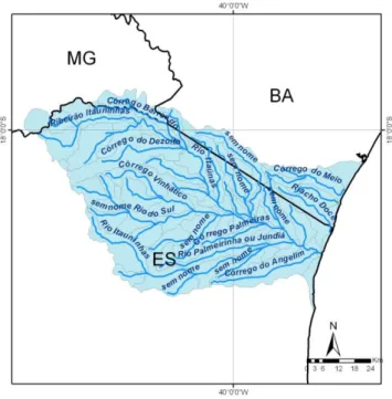
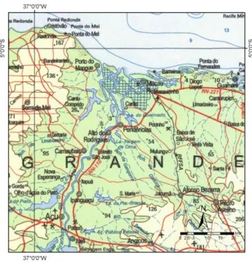
Figura 1 - Localização da área de estudo (Bacia do rio Itaúnas, IBGE,
1:1.000.000) ... 08
Figure 2.1 - Ordering of channel drainage systems (Beckinsale, 1991) ... 11
Figure 2.2.1 - Example of Pfafstetter (1989) coding system... 18
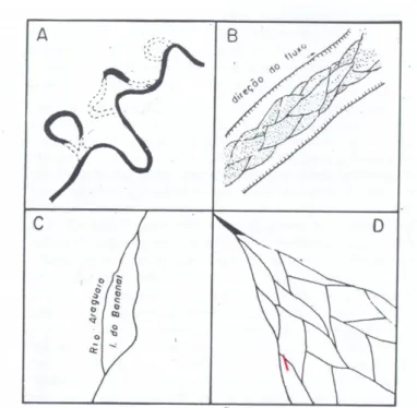
Figure 2.3.1 - Example of river channels: A) Braided, B) Anastomosed, C) Branched, D) Reticulated (Christofoletti, 1981). ... 24
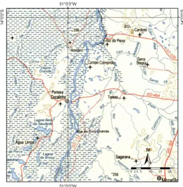
Figure 2.3.2 - Example of branched channel according to IBGE at scale of 1:100.000 ... 25
Figure 2.3.3 - Example of a deltaic channel according to IBGE’s 1:1000.000 chart ... 26
Figure 2.3.4 - Example of anastomasing channel according to IBGE’s 1:1000.000 chart ... 26
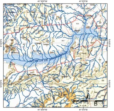
Figure 2.3.5 - Example of classification of natural channels of a Dam according to IBGE’s 1:1000.000 map ... 28
Figure 2.4.1 - Example numbering a basin with double confluence whose both tributaries are located at the same bank of the main stem ... 31
Figure 2.4.2 - Example of numbering a basin with double confluence whose tributaries are located at different banks of the main stem ... 32
Figure 2.4.3 - Example of numbering of a basin with double confluence whose both tributaries are located at the same bank of the main stem ... 33
Figure 2.4.4 - Example of numbering a basin with double confluence whose both tributaries are located at the same bank of the main stem ... 33
Figure 2.4.5 - Example of numbering a basin with double confluences whose tributaries are located at opposite banks of the main stem ... 34
Figure 2.4.6 - Another example of numbering a basin with double confluences whose tributaries are located at opposite banks of the main stem ... 34
Figure 2.4.7 - Example of numbering basins with multiple channels ... 36
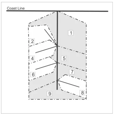
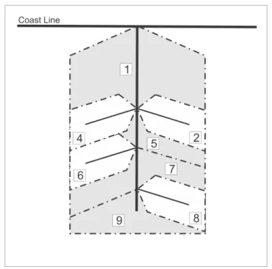
Figure 2.4.8 - Example of numbering basins with river delta ... 37
Figure 2.4.9 - Example of coding basin of a sink/spillway ... 38
Figure 2.4.10 - Example of numbering basins with water mass ... 39
Figure 3.5.1 - Class Diagram of the Hydrographic Information Package ... 57
Figure 3.5.2 - Transformation Diagram – Schema 1 ... 58
Figure 3.5.3 - Transformation Diagram – Schema 2 ... 59
Figura 4.1 - Diagrama de Classes do Pacote de Informação de Hidrografia ... 74
Figura 4.2 - Tabelas núcleo da implementação física do Pacote de Informação de Hidrografia ... 76
Figura 4.3 - Fluxograma geral do processo ... 77
Figura 4.4 - Fluxograma da consistência da rede hidrográfica ... 79
Figura 4.5 - Fluxograma da consistência das Áreas de Contribuição Hidrográfica ... 83
Figura 4.6 - Fluxograma da geração das informações hidrográficas ... 91
Figura 4.7.1 - Trechos e nós da rede de drenagem. Cor verde: Ponto Início Drenagem; laranja: Confluências e Magenta: Ponto Fim Drenagem ... 100
Figura 4.7.2 - Identificação da codificação de bacias hidrográficas de Pfafstetter (1989)... 101
LISTA DE TABELAS
LISTA DE APÊNDICES
APÊNDICE I - Especificação Técnica para a Aquisição de Dados Geoespaciais Vetoriais/Relação de Classes do Diagrama de classes da categoria de informação HIDROGRAFIA ... 115 APÊNDICE II - Especificação Técnica para a Aquisição de Dados Geoespaciais Vetoriais/Construtores de Geometria de Objetos da categoria de informação HIDROGRAFIA ... 173 APÊNDICE III - Diagrama do Modelo Físico do Pacote de Hidrografia ... 272 APÊNDICE IV - Instruções SQL para a Construção do Modelo Físico do Pacote de Hidrografia ... 274 APÊNDICE V - Codificação Principal de Funções e Procedimentos do
CAPÍTULO 1 - INTRODUÇÃO
A Lei Federal no 9.433, de 08 de janeiro de 1997 (Brasil, 1997) institui a Política Nacional de Recursos Hídricos (PNRH) e cria o Sistema Nacional de Gerenciamento de Recursos Hídricos (SINGREH), além de tratar de outras regulamentações.
Dentre os instrumentos da Política Nacional de Recursos Hídricos, o art. 25 da referida lei estabelece que “o Sistema de Informações sobre Recursos Hídricos é um sistema de coleta, tratamento, armazenamento e recuperação de informações sobre recursos hídricos e fatores intervenientes em sua gestão”, e que “os dados gerados pelos órgãos integrantes do SINGREH serão incorporados ao Sistema Nacional de Informações sobre Recursos Hídricos (SNIRH)”.
Os princípios básicos do SNIRH, citados no art. 26 da mesma lei, compreendem a descentralização da obtenção e produção de dados e informações, a coordenação unificada do sistema e o acesso aos dados e informações garantidos a toda a sociedade.
Por fim, o art. 27 define os objetivos do SNIRH, que são: reunir, organizar, dar consistência e divulgar os dados e informações sobre a situação qualitativa e quantitativa dos recursos hídricos no Brasil; atualizar permanentemente as informações sobre disponibilidade e demanda de recursos hídricos em todo o território nacional; e fornecer subsídios para a elaboração dos Planos de Recursos Hídricos.
Um dos fundamentos da Lei no 9.433 (Brasil, 1997) estabelece que “a bacia hidrográfica é a unidade territorial para implementação da Política Nacional de Recursos Hídricos e atuação do Sistema Nacional de Gerenciamento de Recursos
Hídricos”. Isso vai de acordo com o movimento global de gestão de recursos hídricos,
estabelecido desde 1992 na Dublin Conference on Water and the Environment (Verdin & Verdin, 1999).
(Brasil, 2006) e passou utilizá-la como suporte à gestão em seus processos internos.
A metodologia de construção de uma base hidrográfica ottocodificada tem como objetivo compatibilizar as unidades de gestão utilizadas em recursos hídricos, visto que a Lei no 9.433/1997 (Brasil, 1997) define a bacia hidrográfica como unidade de planejamento e gestão dos recursos hídricos nacionais e a Resolução no 30 do Conselho Nacional de Recursos Hídricos (CNRH) (Brasil, 2003) adota o sistema de codificação de bacias hidrográficas proposta por Pfafstetter (1989) como instrumento de referência utilizado na Política Nacional de Recursos Hídricos (PNRH).
A metodologia de construção de uma base hidrográfica ottocodificada proposta pela ANA (Brasil, 2006) consiste de um conjunto de processos em ambiente desktop para tratamento topológico da rede hidrográfica com base no sistema de codificação de Otto Pfafstetter (1989) que permite associar e extrair informações a jusante e a montante de cada trecho da rede hidrográfica, por exemplo.
1.1 Definição do Problema
Em termos práticos, a manipulação de dados e informações de recursos hídricos para atender ao Sistema Nacional de Informações sobre Recursos Hídricos (SNIRH) requer um apelo geográfico e espacial significativo, pois a representação espacial de cursos d’água, nascentes, fozes, usuários de água, barragens, entre outros e as informações geométricas e espaciais derivadas dessas representações são decisivas na tomada de decisão em recursos hídricos.
Desde quando se começou a tomar decisões em recursos hídricos a partir da manipulação de dados espaciais por meio de Sistemas de Informações Geográficas (SIG), a arquitetura tecnológica utilizada era comumente baseada em sistemas desktops, em que dados e informações estavam descentralizadas e localizadas no próprio computador do usuário. Quando possível, essas informações eram disponibilizadas à sociedade por meio de CDs e DVDs. Pelas características apresentadas, essa solução atendia parcialmente aos princípios e objetivos do SNIRH, que, dentre outras prerrogativas, exige o acesso aos dados e informações garantidos a toda a sociedade.
os órgãos dos poderes públicos federal, do Distrito Federal, estaduais, e municipais cujas competências se relacionem com a gestão de recursos hídricos e as Agências de Água.
Com o amadurecimento e maior acessibilidade às ferramentas de sistemas computacionais corporativos é possível integrar os sistemas desenvolvidos para gestão de recursos hídricos dos membros que compõem o Sistema Nacional de Gerenciamento de Recursos Hídricos (SINGREH). Dentre as tecnologias existentes podem-se citar os Sistemas Gerenciadores de Banco de Dados Geográficos e a Arquitetura Orientada a Serviço (SOA) (Bell, 2008).
Os membros do SINGREH desenvolvem seus próprios sistemas de gerenciamento de recursos hídricos e, no que diz respeito à origem dos dados geográficos, utilizam como referência espacial a base hidrográfica cartográfica na escala de detalhe que melhor lhes convém. Com o intuito de compatibilizar as diferentes escalas cartográficas das bases hidrográficas desses sistemas com a base hidrográfica de referência do SNIRH, a ANA desenvolveu uma metodologia de construção de uma base hidrográfica ottocodificada (Brasil, 2006). Esta base é compatível com as unidades de gestão de recursos hídricos definidas pela Resolução no 32, de 15 de outubro de 2003 do CNRH (Brasil, 2003), pois ambas são baseadas no sistema de codificação de bacias hidrográficas proposto por Pfafstetter (1989).
Apesar das vantagens do sistema de codificação de Pfafstetter (1989), a principal limitação desse sistema de codificação está relacionado à representação da rede hidrográfica por meio de um grafo binário do tipo anti-arborescência (Netto, 2006). Esse tipo de representação é caracterizada pela orientação do arco das folhas para a raiz, ou de montante para jusante, com a convergência de dois arcos em um nó, com exceção do nó que representa a foz ou a anti-raiz da arborescência, onde um único arco converge em um único nó. A anti-arborescência também exige que todos os arcos estejam conexos e que não existam ciclos ou enlaces (Netto, 2006).
hidrográfica por meio de uma anti-arborescência não é possível em regiões onde existam canais múltiplos dos tipos ramificado, anastomosado, reticulado, deltaico ou labirínticos em trechos rochosos (Christofoletti, 1981).
Assim, a adoção da metodologia de construção de uma base hidrográfica ottocodificada proposta pela ANA (Brasil, 2006) não resolve completamente a compatibilidade das diferentes escalas de mapeamento cartográfica de onde se originaram as bases hidrográficas. As inconsistências cartográficas que podem ser observadas na base espacial onde foi aplicada essa metodologia advêm em grande parte da representação da rede hidrográfica por meio de um grafo binário do tipo anti-arborescência e do mapeamento sistemático cartográfico que lhe deu origem.
Uma forma de melhorar a qualidade dos elementos que representam a rede hidrográfica é aderir o Modelo Digital de Elevação aos elementos de hidrografia do mapeamento sistemático para geração do Modelo Digital de Elevação Hidrologicamente Consistente (MDEHC) com a geração sintética dos elementos que compõem a bacia hidrográfica, como cursos d’água e divisores de bacia. Além disso, o MDEHC é condição primordial para que ferramentas de simulação dinâmica sejam integradas à base hidrográfica ottocodificada, como modelos distribuídos chuva-vazão, modelos de propagação de água subterrânea, modelos hidráulicos que dependem da informação de declividade do leito do rio, entre outros.
A adoção de um MDEHC como elemento estruturador dos diversos elementos que compõem uma base hidrográfica ottocodificada é um aspecto da maior relevância quando se tem em foco a destinação maior dessa base, que é a integração e compatibilização das informações espaciais do Sistema Nacional de Informações sobre Recursos Hídricos (SNIRH).
Vale dizer que, sem a adoção do MDEHC para a estruturação de uma base hidrográfica ottocodificada, tem-se uma dissociação entre a base hidrográfica do mapeamento sistemático e o modelo de elevação de superfície, o que certamente acarretará problemas à medida que forem implementados módulos mais avançados de análise hidrológica.
É interessante que qualquer base hidrográfica utilizada na tomada de decisão em recursos hídricos leve em consideração as especificações técnicas para a Aquisição e Estruturação de Dados Geoespaciais Digitais Vetoriais (ADGV/EDGV), componente da Mapoteca Digital Nacional (MND) da Infraestrutura Nacional de Dados Espacial do Brasil (INDE). Apesar da ADGV/EDGV ser uma referência, a sua proposta para a categoria de informação HIDROGRAFIA carece de revisão para que esta seja aderente ao sistema de codificação de bacias de Otto Pfafstetter (1989).
1.2 Justificativa do Trabalho
Apesar da codificação de bacias de Otto Pfafstetter (1989) ser referência nacional na gestão de recursos hídricos (Brasil, 2003), essa metodologia possui limitações inerentes à representação vetorial da rede hidrográfica, pois não permite a representação de canais anastomosados, confluências múltiplas ou trechos segmentados. Para este trabalho, sugere-se um aprimoramento ao sistema de codificação de bacias hidrográficas baseada na proposta de Pfafstetter (1989) que solucione essas limitações.
A proposta da ANA de construção de uma base hidrográfica ottocodificada (Brasil, 2006) utiliza atualmente uma série de procedimentos manuais e descentralizados que são executados por meio de uma plataforma SIG (ArcGIS/ArcInfo) (ESRI, 2012) e de um repositório de dados (Microsoft Access). Esses processos são executados por meio da manipulação de dados geoespaciais em plataforma SIG e por meio de consultas presentes no repositório de dados e em formato proprietário Geodatabase (ESRI). Além disso, a solução atual não permite a conexão com dados espaciais nativos de outros sistemas gerenciadores de banco de dados geográficos, sejam eles proprietários como o Oracle Spatial (Oracle, 2012), ou software livre, como o PostGIS (PostGIS, 2012).
Geospatial Consortium (OGC, 2012) adotados pelo Governo Eletrônico Brasileiro (Brasil, 2007) e pela INDE (Concar, 2012) não está de acordo com as especificações técnicas para a aquisição e estruturação de dados geoespaciais digitais vetoriais (ADGV/EDGV) estabelecidos pela Comissão Nacional de Cartografia (Concar, 2012).
O estágio mais recente de formulação de uma proposta para construção de uma base hidrográfica ottocodificada indica a adoção dos elementos que derivam do Modelo Digital de Elevação Hidrologicamente Consistente (MDEHC), bem como a revisão da aplicação do sistema de codificação de bacias de Pfafstetter (1989) que seja baseado em ferramentas de sistema gerenciador de banco de dados geográficos.
A presente pesquisa engloba estudos que contribuem com o processo de construção de uma base hidrográfica ottocodificada automatizado com uma significativa redução dos custos operacionais de implantação, baseado em sistema gerenciador banco de dados geográficos e sistema de informações geográficas livres (open-source). Essa contribuição facilitará a disseminação da metodologia junto aos membros do SINGREH que desejem implementar uma base hidrográfica ottocodificada em seus sistemas em escalas de maior detalhe que a atualmente utilizada na ANA (1:1.000.000) (Teixeira et al., 2007). Além disso, essa proposta permite o continuo desenvolvimento dessa tecnologia por meio da colaboração em massa por todos os interessados nesse processo.
Assim, justifica-se a execução dessa tese, pois ao final ter-se-á: a) um aprimoramento do sistema de codificação de bacias hidrográficas baseada na proposta de Pfafstetter (1989) que solucione as suas principais limitações, b) nova proposta de construção de uma base hidrográfica ottocodificada em banco de dados geográficos; c) utilização dos elementos derivados do modelo digital de elevação hidrologicamente consistente (MDEHC) para a construção de uma base hidrográfica ottocodificada; d) desenvolvimento da inteligência hidrográfica em banco de dados geográficos para tomada de decisão em recursos hídricos; e e) estudo de caso com aplicação das tecnologias propostas na escala de mapeamento 1:1.000.000.
1.3 Objetivos
1.3.1 Objetivo Geral
1.3.2 Objetivos Específicos
Em função do objetivo geral traçam-se os seguintes objetivos específicos:
(1) Apresentar aprimoramento do sistema de codificação de bacias hidrográficas baseada na proposta de Pfafstetter (1989), que solucione as limitações inerentes à representação da rede hidrográfica por meio de um grafo binário do tipo anti-arborescência;
(2) Apresentar novo modelo conceitual em banco de dados geográficos baseado
na categoria de informação “Hidrografia” das especificações técnicas para aquisição e
estruturação de dados geoespaciais vetoriais (ADGV/EDGV) da Mapoteca Nacional Digital (MND), componente da Infraestrutura Nacional de Dados Espacial (INDE), que seja compatível com a codificação de bacias hidrográficas de Pfafstetter (1989);
(3) Implementar em sistema gerenciador de banco de dados geográficos objeto-relacional o novo modelo conceitual baseado na categoria de informação “Hidrografia” das especificações técnicas para aquisição e estruturação de dados geoespaciais vetoriais (ADGV/EDGV) da Mapoteca Nacional Digital (MND);
(4) Desenvolver os algoritmos que fazem parte da metodologia de construção de uma base hidrográfica ottocodificada em sistema gerenciador de banco de dados geográficos objeto-relacional;
(5) Apresentar um estudo de caso na bacia do rio Itaúnas da aplicação da metodologia de construção de uma base hidrográfica ottocodificada em banco de dados geográficos e que seja hidrologicamente consistente para tomada de decisão em recursos hídricos.
1.4 Área de Estudo
A área de estudo teórico compreende as áreas de conhecimento de tecnologia da informação, modelagem conceitual de banco de dados geográficos, sistema gerenciador de banco de dados geográficos (SGBDG), grafos, sistemas de codificação de bacias hidrográficas, sistema de informações geográficas (SIG), interoperabilidade e padrões geotecnológicos internacionais, análise espacial e topológica, álgebra relacional e modelagem hidrográfica.
Itaúnas apresenta 5.298 km2 e está localizada entre os estados do Espírito Santo, Minas Gerais e Bahia. Os principais rios dessa bacia costeira são os rios Itaúnas, Itauninhas, Palmeirinha e do Sul.
Figura 1 - Localização da área de estudo (Bacia do rio Itaúnas, IBGE, 1:1.000.000).
1.5 Origem dos Dados e Informações
Os dados e informações utilizadas nessa pesquisa são oriundos de fontes secundárias disponibilizadas por outras instituições, principalmente de dados do mapeamento cartográfico do IBGE e dados do modelo digital de elevação do projeto Shuttle Radar Topographic Mission (SRTM) (Nasa, 2012).
A rede hidrográfica utilizada nesse trabalho é a base digital vetorial do mapeamento cartográfico do IBGE na escala 1:1.000.000. As áreas de contribuição hidrográficas foram obtidas como produto derivado do modelo digital de elevação hidrologicamente consistente obtido pelo modelo digital de elevação do projeto Shuttle Radar Topographic Mission (SRTM) (Nasa, 2012) com a aderência da rede hidrográfica do IBGE na escala 1:1.000.000.
1.6 Modelo Analítico
CAPÍTULO 2 - BASIN CODING SYSTEM BASED ON PFAFSTETTER’S PROPOSAL
Abstract
Notable amongst the various proposals for codification of basins is Otto Pfafstetter's proposed numbering system, whose digit-codes carry out the topological relationship between the stretches of the drainage network. However, despite Pfafstetter system has been widely used as the basis for the development of several information systems on water resources, it places inherent limitations in the representation of river systems by means of a binary anti-arborescence graph-type that have led to the loss of hydrographic information when the drainage network is simplified.
In view of that, the present research paper seeks to undertake a comprehensive literature review of existing basin coding systems and to present a new scheme for the numbering and ordering of watersheds based on Otto Pfafstetter's system. In the end, the proposed scheme shall maintain the simplicity of Pfafstetter's label code while preventing the loss of hydrographic information.
2.1 Introduction
The ordering or numbering of drainage system channels aims to contribute to the management of water resources based on a hierarchical classification of watersheds that make use of different criteria and approaches. To that end, several proposals for codification of watershed areas have been formulated so far, both in Brazil and abroad.
Beckinsale & Chorley (1991) state that one of the first studies undertaken to order and hierarchize branches within a drainage basin goes back to Jackson (1834). In his work, Jackson (1834) proposes a classification scheme in which the stream that flows into the sea is classified as a first-order stream, while the second-order stream is formed by the junction of two first-order streams, and so on. The analysis is performed from downstream to upstream, and the sea is the initial reference (Figure 2.1).
basins have the same stream order, there would still be remarkable difference among their sizes.
Horton (1945) proposed in his methodology that drainage channels which have no tributaries should be considered first-order streams. Second-order channels are those which have as tributaries only first-order streams (Figure 2.1). Third-order channels receive of second-order or first-order tributaries, and so forth, from the source to the mouth of the basin.
The method of stream order classification proposed by Strahler (1957) was based on the first part of Horton’s proposed stream-ordering (1945). According to Strahler (1957), first-order streams are those having no tributaries, second-order streams are formed when two first-order streams come together downstream, and so forth to the mouth of the basin. When streams of unequal order join each other, the stream downstream of the junction has the same order as the higher order stream.
Tucci (1993) states that the main difference between Horton’s (1945) and Strahler’s (1957) stream-coding is that Strahler’s system (1957) considers that the main stream and tributaries do not maintain the order number in all of its extensions as is the
case with Horton’s system (1945). Another difference is that Strahler’s stream-coding
(1957) considers that all channels having no tributaries are of first order, including the headwaters of major rivers and tributaries. This is contrary to the subjective Horton’s criterion (1945) as regards determining the source.
Figure 2.1 - Ordering of channel drainage systems (Beckinsale, 1991).
2.2 Basin Coding Systems
Among some efforts made abroad for the determination of basin coding systems, Verdin & Verdin (1999) highlighted the work of the U.S. Geological Survey (USGS) (Seaber et al., 1987), the U.S. National Water Information System (NWIS) (Wahl 1985), the French ORSTOM (Roche, 1968) and the Global Runoff Data Centre (GRDC, 1996) to the World Meteorological Organization coordinated by the Federal Institute of Hydrology in Koblenz, Germany. However, neither of the codification systems proposed by these organizations have employed digits which carry topological information on the links between the stream segments.
The USGS Division of Water Resources has proposed the division of the U.S. territory in 21 river basin regions composed of 222 subregions. In this proposal, hydrologic unit boundaries for drainage basins greater than 700 square miles (1,800 square kilometers) are depicted, except for Alaska. Each hydrologic unit is identified by a hydrologic unit code consisting of an eight-digit number that has two digits each to indicate the region, subregion, accounting unit and cataloging unit. For each level of classification, there is an estimated association of catchment area of approximately 500,000 square kilometers for regions, 50,000 square kilometers for the subregions, 25,000 square kilometers for the accounting units and 4,000 square kilometers for cataloging units (Seaber et al., 1987).
The US National Water Information System (NWIS) is the repository for stream gauge stations of the USGS surface water and employs a system based on the drainage system for the numbering of these stream gauge stations. The identification number of stream gauging stations consist of eight-digit numbers whose ordinal values increase in a downstream sense. The position of a station on a tributary is indicated by an indentation of the number, and there is successive indentation to indicate the tributary rank. Numbers themselves do not offer any distinction between the tributary and the main stream, nor do they indicate the drainage system topology (Wahl, 1985).
The French research organization, ORSTOM, presents another example of classification applied to the drainage system for the identification of stations, based on a nine-digit system. The first digit of the proposed system identifies the continent where the station is found, the second and third digits identify the country. The fourth and fifth digits identify the main river where the station is located. To this end, the ORSTOM selects and sorts the 99 major rivers of the continent in alphabetical order. The sixth and seventh digits are used to identify the stream where the gauging station is positioned, and the eighth and ninth digits are the numerical order of the station itself (Roche, 1968).
In 1972, the former National Hydroelectric Power Agency of Brazil, DNAEE, proposed the first coding system to identify gauging stations that formed the Hydrological Information System (Ibiapina et. al., 1999). This system is very similar to the one proposed by NWIS (Wahl, 1985).
DNAEE codification scheme uses two digits to represent basins and subbasins, and six digits to identify the station number. The first digit represents one of the eight basins in which the country was divided into, except for number 9, which is used to determine any basin in South America with no network interference in Brazil (Galvao & Meneses, 2005). Each of these basins is divided into ten major subbasins numbered from 0 to 9. Digits from three to eight are used to identify station numbers, with values increasing from upstream to downstream (Fernandes, 1987).
Late Otto Pfafstetter (1989), an engineer with the former National Bureau of Sanitation Works (DNOS), proposed a new codification system for watershed classification which was later employed by the National Irrigation Register (Rubert & Figueiredo, 2001) of the former National Irrigation Department. This system employs the ten digits of the base-10 numbering system and was devised to exploit the features of the catchment area, its topology or connectivity and drainage system position. Compared to other codification systems, Pfafstetter’s (1989) coding system has several advantages, since it is a natural, hierarchical method based on the topography of the drained area and the topology of the drainage system. Besides, the codes convey topological information (Galvao & Meneses, 2005).
Institute of Environment and Renewable Natural Resources (IBAMA). The codification was based on the system devised by Pfafstetter (1989) and was detailed up to level 5 of the river system (Silva, 1999).
Following the review and modifications to Silva’s (1999) approach by means of an agreement with the Development Company of the Sao Francisco Valley (Codevasf), it was possible to detail Level 1 regions delineated by Pfafstetter’s (1989) coding system (Rubert & Figueiredo, 2001). In this paper, Rubert & Figueiredo (2001) state that the resulting Level 1 codification differs from that one proposed by Pfafstetter (1989). The difference is due to three main factors: the digital and most accurate nature of the river system, the basemap at a scale of 1:1000.000 and the change of the boundary between number one and number nine basins.
Parallel to this effort, in 2000 the Brazilian Institute of Geography and Statistics (IBGE) presented a general classification for Brazilian river basins that divided them into 10 basins and 57 subbasins based on the cartographic mapping at scale of 1:1,000,000.
In 2002, Brazil’s National Council of Water Resources (CNRH) approved the Resolution n. 30 (Brazil, 2003) establishing Pfafstetter coding system (1989) as a reference tool to be used in the National Water Resources Policy (Silva, 1999).
In 2003, the CNRH established the National Water Division, which was composed of 12 Level 1 hydrographic regions and 30 Level 2 regions through Resolution n. 32 (Brazil, 2003). In order to guide the planning and management of water resources, the delineation of these regions is not limited to their hydrographic features, as they are characterized by the Brazilian territorial space within a basin, group of adjacent basin or subbasins with homogeneous or similar natural, social and economic characteristics.
Brazil’s National Water Agency (ANA), established in 2000 by Law 9,984 (Brasil, 2000) for the management of Brazil’s hydro-meteorological network, has employed the DNAEE coding system (Fernandes, 1987) to identify gauging stations to date. However, in 2006 ANA introduced a hydrological database for the Brazilian
territory based on Pfafstetter’s coding system at the scale of 1:1000.000 (Brasil, 2006;
the system. Unlike previous works, this database is not limited to numbering basins up to Pfafstetter Level 5. Instead, considering that the development process of this database was carried out in a computing environment and involving a Geographic Information System (GIS), the catchment areas of all stream segments have been numbered, with 96.38 percent of Pfafstetter basins being of at least Pfafstetter Level 6 (Teixeira et al., 2007a).
Pfafstetter coding system has been implemented abroad since 1997, including by Verdin (1997) for the numbering of the North American continent and by Verdin & Verdin (1999) for the numbering of the seven continents in the world, except Antarctica, using GIS techniques based on the GTOPO30, an elevation model produced by the U.S. Geological Survey.
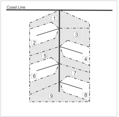
The Norwegian National Catchment Database (REGINE, 2009) was established and maintained by the Directorate Norwegian Water Resources and Energy (NVE). Norway’s coding system of hydrographic units proposed to REGINE form a hierarchy, each level being more detailed than the last. This hierarchical classification comprises the following nine categories: 1) Water system area, 2) River basin, 3) Sub-unit in river basin, 4) Central catchment, 5) Sub-unit in central catchment, 6) Edge area, 7) Sub-unit in edge area, 8) Coastal area, 9) Sub-unit in coastal area.
The REGINE coding system is composed of several levels and criteria for codification. It is very complex compared to other existing coding systems (Flavin et al., 1998).
The basin coding system proposed by the German Working Group on Water (Länder-Wasser-Arbeitsgemeinschaft – LAWA) in 1993 (Flavin et al., 1998) is very similar to Pfafstetter’s proposed coding system (1989), the major difference being that the codification in the first starts from the source towards the mouth of the river and not from the mouth as in the latter. Besides, in relation to the LAWA proposal, the greater the number of the code, the greater the increase in drainage area. Another feature of the LAWA system (1993) is that it does not provide digit numbers for coastal basins, only for continental basins (Flavin et al., 1998).
of those databases into the monitoring program of the EEA member states by means of a coding system using indirect spatial reference (Flavin et al., 1998).
The ERICA codification system consists of four parts: (1) two-digit code for sea basins where the river flows into, (2) three-digit code for the shoreline code, (3) digit code for basin and inter-basin areas (4) and a basin-area-indicator.
Still, the ERICA system proposes that the codification of basins and interbasins is carried out for each coding cycle within a catchment area, whereby the 49 largest tributaries of the main river within that area are identified and numbered using even numbers from 2 to 98. Thereafter, interbasins located between major tributaries shall be assigned odd numbers between 1 and 99.
The development of the ERICA codification system followed an evaluation of the European systems REGINE and LAWA, which had been deemed unclear or inconsistent when dealing with shorelines, respectively (Flavin et al., 1998). According to Nery et al. (2001), the most challenging point about ERICA system was the difficulty to identify the 49 major tributaries of each of the European rivers, especially in the treatment of smaller catchment areas.
The European Union Members, Norway and the European Commission have jointly developed a common strategy for supporting the implementation of Directive 2000/60/CE, or Water Framework Directive (WFD), establishing a Community action plan in the field of water policy. The main objective of this strategy was to enable a coherent and appropriate implementation of Directive 2000/60/CE while focusing on methodological issues related to a common understanding of its technical and scientific implications. Therefore, the implementation of the GIS elements of the Water Framework Directive proposed a basin coding system based on Pfafstetter system (1989), with the inclusion of a pair of two digit codes each to be assigned before Pfafstetter digit codes. Both codes are composed of the 2-character Member State identifier of the Member State responsible for code assignment and the Marine Waters identifier code in accordance with the International Hydrographic Organization (Vogt, 2002). The code takes the following form: MS MW N1 N2 N3...NN.
drained hydrological objects of the European continent based on the delineations of the seas and oceans as well as river basins in continental landmasses and islands.
In 2009, Furst & Horhan applied the LAWA coding system (1993) for Austria’s rivers and basins (the Danube, the Rhine and the Elbe), which is a modified version of the Pfafstetter system. The major difference here is that the order of numbering is downstream from the source to the mouth instead of upstream as originally proposed by Pfafstetter. Another feature of the coding system proposed by Furst & Horhan (2009) is that the criterion for defining the main stem within a basin would be first by name and second by the main stem being defined as having the longest flow path, i.e. drainage area upstream.
Furnans (2001) developed a computing algorithm that is based on Pfafstetter coding system (1989) for defining stretches of drainage system upstream of the mouth of a particular point and applied for the Yangtze River Basin, China (Furnans & Oliveira, 2001).
Silva et al. (2008) proposes a modified version of Pfafstetter coding system (1989), whose main reference is based on the size of the stretch of drainage system instead of the size of the catchment area as originally proposed by Pfafstetter (1989). Silva et al. (2008) also suggests the adoption of this method if no catchment area within a basin is available.
Another proposal for basin numbering system was put forward by Figueiredo (1999), who suggested the numbering of all streams of the drainage system through the systematic mapping of the state of Minas Gerais at scale of 1:100,000. This proposal was based on the DNAEE system as regards the name of the stream, the order and the bank of the tributary. The codification consists of numbers and letters, where the first two digits identify streams within the basin and sub-basin based on the codification proposed by DNAEE. The remaining digits indicate, from downstream to upstream, the order of the main tributary, and the left (L) and right (R) banks. This procedure is performed until the last body of water upstream has been numbered. Although the adopted criterion is based on the name of the river and does not take into account the discharge or the catchment area upstream, this scheme allows the identification of all streams that are downstream of a particular river that has already been labelled.
are for inter-basins. The zero number is for basins draining into the sea or endorheic basins.
Pfafstetter (1989) defines as main stem of the basin the group of stretches of connected stems with the highest annual runoff. However, as the general annual runoffs are approximately proportional to the areas of their basins, this variable is used as a criterion for numbering. Interestingly, Pfafstetter system (1989) should not be employed in regions with high climate variability.
Thus, it is possible to delineate the four tributaries with the largest drainage areas discharging to the main stem from downstream to upstream at any level of classification. At each point of bifurcation, the tributary is defined as the smaller drainage area and main stem is defined as the one with the largest area. The four major tributaries of the main stem in each branch level are assigned even numbers 2, 4, 6 or 8 from downstream to upstream. The four major tributaries are once again delineated for each one of these tributaries by simply assigning a value to the end of the Pfafstetter digit code of the next lowest level and so forth until all the streams within the drainage system have been numbered. All other tributaries within a main river are grouped into five areas designated by Pfafstetter (1989) as inter-basins, which are assigned the odd numbers 1, 3, 5, 7 and 9, again moving from downstream to upstream (Figure 2.2.1).
Although Pfafstetter (1989) claims that the partial basins of the headwaters of each river are inter-basins because they are assigned, in effect, the final digit code 9, there are cases where this code could be 3, 5 or 7, such as when there are only 1, 2 or 3 tributaries of the main stem, respectively. Apart from that, Pfafstetter (1989) stressed that the area of partial basins of each headwater would be larger than the area of the last tributary.
Among the potential disadvantages or difficulties of this approach pointed out by Pfafstetter (1989) is that a simple analysis of the code can draw conclusions such as: if a basin has the first number, or the number farther to the left, and is an odd number, then the stream is part of one of the four coastal basins under evaluation. On the other hand, if this code farther to the left is an even number, the stream is part of one of the four major tributaries of the basin under evaluation. Besides, any simple analysis of the digit code helps to identify which stream is upstream or downstream of any particular point.
Pfafstetter coding system (Pfafstetter, 1989) is based on a discrete model of vector and geospatial data represented by drainage areas, where each area is associated to a river stretch that has been defined as of drainage segment beginning or ending with a confluence, and may characterize or not the source or the mouth of the stream, respectively.
By making an analogy of the drainage system studied by Pfafstetter (1989) and graph theory, the river system can be described as an anti-root connected graph without oriented cycles, known as anti-arborescence (Netto, 2006). Such a statement is based on the fact that the stream flow is oriented from the leaves towards the anti-root, i.e. from the source to the mouth. Netto (2006) also notes that the arborescence (tree) is associated with the idea of hierarchy or classification, and therefore is of order relation, ruled by a single element. These features indicated by Netto (2006) are crucial as a tool to help in decision-making procedures related to water resources, because their management is carried out at different levels. Besides, the drainage system cannot be considered as being a tree in graph theory because a tree is a connected graph with no cycles and no orientation.
In 2006, the Brazilian National Water Agency (ANA) presented the Brazilian Pfafstetter System Database to the community at the scale of 1:1000.000 (Brasil, 2006; Teixeira et al., 2007a,b) composed of hydrographic network and catchment areas. This database was developed on the grounds of Otto Pfafstetter system, and consists of a series of data repository and geoprocessing procedures for the numbering of watershed in line with Pfafstetter’s proposed coding system (1989).
The main purpose of this method is to provide the community with a mechanism that can be used by other water resource managers for the standardization of the current reference hydrographic database. The standardization of this hydrographic database was proposed with the aim of meeting the objectives of the Brazilian National Water Resource Information System (SNIRH), specifically with regards to the treatment of geospatial data on the drainage system for the provision of information for the system as a whole.
Based on Pfafstetter System Database, it is possible to identify the relationship between the different river stretches and to deal with issues related to the position of elements along the drainage system, such as which river is downstream or upstream of any particular reference point.
This method also presents the hydrographical elements modeled as a geographic database, using for this purpose the OMT-G geographic data model (Borges et.al., 2001). Therefore, in accordance with this method, the Pfafstetter System Database modeled as part of a series of geospatial logical data elements such as Mouth, Confluence, Confluence-Mouth, Spring, River Stretch, Stream, River and Pfafstetter basin.
The definition of the logic element watercourse adopted in this model is consistent with the technical criteria for identifying Brazilian watercourses and their classification as to the level, whether federal or state, set out in Resolution No. 399 of 2004 of the National Water Agency (Brazil, 2004). The same definition is in accordance with the main stem described by Pfafstetter (1989) in his proposed coding system.
The methodology for the development of a Pfafstetter System Database (Brazil, 2006) adds two new concepts to Pfafstetter coding system (1989): the watercourse code and the river code. Originally, Pfafstetter coding system (1989) is focused on basin codification, but the association of basin codification to the related watercourse is inherent in the development process. That is remarkable in the very description of Pfafstetter’s codification methodology (1989) when it defines the main basin watercourse and four major tributaries.
Thus, according to the methodology for the development of the Pfafstetter System Database, the watercourse code stems from the basin code itself, while all odd numbers are set aside, from right to left, until the first even number has been reached. This procedure leads to the deletion of the code number of the inter-basin, i.e. it presents the basin digit code of the main watercourse where the inter-basin is in between.
The river code stems from the watercourse code and it was designed to distinguish stretches of any connected watercourse with the same toponym. To this end, the watercourse code further upstream is used, adding to it the next river’s name present in that watercourse. This river code aims to systematize the names given to drainage, such as generic names (river, arroyo, stream, brook, etc.), linking names (of) and specific names (Amazon, Sao Francisco, Araguaia, Tocantins, etc.).
A series of pre-processed information is associated with elements that compose the Pfafstetter System Database other than the basin. This pre-processed information falls into three categories: native, hydroreferenced and aggregated (Brazil, 2006).
The concept of hydroreferencing (Brazil, 2006) established by the development method of the Pfafstetter System Database includes the projection of specific geometric features in the Pfafstetter System Database. Based on this projection, it is possible to link pre-processed information in the hydrographical network with the projected point. Similarly to the georeferencing process of a point, instead of providing latitude or longitude of a point, the hydroreferencing provides the watercourse’s code related to the projected point and its native information.
Hydroreferencing (Brazil, 2006) puts forward as a solution the integration of Pfafstetter System Database developed under cartographic mapping at different scales considering that the code and detail of a basin’s code can change within coexisting watercourses, while the watercourse code remains the same. The distance to the mouth of the basin may vary because of the detail of the drainage with the largest scale and, as a result, increased distance to the mouth of the basin. Nevertheless, it is possible to apply a correction factor between the scales to estimate the approximate distance of the mouth of the basin at different scales.
The inclusion of spatial information into the Pfafstetter System Database, which describes the physical features of the topography, is possible through the intersection of these information plans with the catchment areas. Thus, pre-processed aggregated information is limited to the representation of elements that form the base, in this case the boundaries of catchment areas. Any needed information that does not fall within this context is limited to that type of representation, such as finding out about specific aggregated information upstream of any particular point located in the middle of a watercourse stretch. Then, under the development methodology of Pfafstetter System Database (Brazil, 2006), it is suggested to apply a hybrid model, composed of a hybrid solution that consists of a discretized model represented by the Pfafstetter System Database and a continuous model based on incremental area, as determined by hydrologically consistent digital elevation model.
2.3 Limitations of Pfafstetter Basin Coding System
the drained area, in which the drainage system topology can be identified through the digits code, and is easily implemented by a computer program, as well as the Geographic Information System (GIS).
These advantages allowed the dissemination of Pfafstetter system (1989) in the international community and adoption, for example, by the USGS for the numbering of basins worldwide (Verdin & Verdin, 1999), and more recently by the European Commission for the implementation of the elements that form the Geographic Information System of the Water Framework Directive (WFD).
Despite the advantages of Pfafstetter coding system (1989), the main limitation of this coding system is related to the representation of the river system by means of an anti-arborescence binary graph (Netto, 2006). This type of representation is characterized by the direction of the arc from the leaves towards the root, i.e. from upstream to downstream, with the convergence of two arcs on a node, except the node that represents the mouth or the anti-root of the arborescence structure, where a single arc converges on a single node. The anti-arborescence structure also requires that all arcs are connected and do not present cycles nor loops (Netto, 2006).
Figure 2.3.1 - Example of river channels: A) Braided, B) Anastomosed, C) Branched, D) Reticulated (Christofoletti, 1981).
Figure 2.3.2 - Example of branched channel according to IBGE at scale of 1:100.000.
Reticulated channels (Christofoletti, 1981) are characterized by the overlapping of channels that split apart and rejoin on a random basis, somewhat resembling anastomosed channels, with the only difference that the flow in reticulated channels is ephemeral and channels are sub-divided into several mouths that drain into lowlands or temporary lakes.
Figure 2.3.3 - Example of a deltaic channel according to IBGE’s 1:1000.000 chart.
Thus, the spatial representation of Pfafstetter drainage system (1989), as well as of all other proposed drainage coding systems, has a limitation in areas where the drainage system has multiple junctions or branched channels with cycles in the delta mouth, anastomosing, branched and braided channels.
Another problem related to the representation of the river system is the presence of sinks and water masses. Currently, these limitations are overcome by simplifying the drainage system where these phenomena occur. The procedures for such a simplification are subjective, and even in situations where systematized and computational processes are used (McAllister, 1999) too much hydrographic information is lost.
Moreover, although uncommon, in nature there are situations where three or more drainage channels converge to a single point. This phenomenon is known as multi-confluences, the most typical example of which is the double confluence. The problem with this type of phenomenon under Pfafstetter system coding (1989) is that when numbering the four major tributaries downstream to upstream, the double confluences shall theoretically be at the same level after odd numbers are assigned. Currently, this has been solved by inserting a small drainage stretch in between both confluences, moving the stretch to downstream or upstream. While resolving the ambiguity of the codification, this attitude does not represent the real nature of the drainage system.
In regions where there is a delta mouth (Christofoletti, 1981), the mouth is usually simplified into a single drainage channel that empties to the sea. Even the presence of significant islands within river water masses makes the representation of the hydrographic network without cycles or loops more difficult. The simplification of the drainage system in these regions as an anti-arborescence structure is very complex, if not impossible. Any solution to make the codification drainage system simpler involves a considerable distortion of the actual features of the hydrographic area.
The representation of the river system in a karst region poses a problem inherent in this type of region, specifically the presence of sinks and the resulting interruption of the drainage system. The representation of the river system through Pfafstetter coding system (1989) in an anti-arborescence structure does not allow the drainage system to be disrupted.
representation of the natural channel of the river before the very emergence of that water mass or the representation of a central line over a very wide river (Figure 2.3.5).
Figure 2.3.5 - Example of classification of natural channels of a Dam according to IBGE’s 1:1000.000 map.
McAllister (1999) proposes a series of computational geometric algorithms within geographic information systems to define the centerline of bodies of water or rivers that match with the representation of the river system under Pfafstetter coding system (1989) in an anti-arborescence format. Although his representation is systematized and does not resort to the errors inherent in manual and subjective process, still there is loss of hydrographic information.
2.4 Improvements on Pfafstetter Basin Coding System
The Pfafstetter coding system (1989) can be summarized as follows:
a) the main stream of the basin is defined from the mouth to the source of the main stream, where the only criterion looked at is the largest area upstream at each point of bifurcation in the river system;
b) the four largest tributaries stemming from the main stream are identified; c) the four largest tributaries are assigned the numbers 2, 4, 6 and 8 from
downstream to upstream;
d) inter-basins, which are found in between coded basins, receive the odd digits 1, 3, 5, 7 and 9 from downstream to upstream;
e) steps from (a) to (d) are repeated for each of the tributaries of the main stream, and a new digit is added to the end of the codification. This procedure is applied recursively until all stream segments have been coded. The improvements on Pfafstetter basin coding system (1989) consists of the following steps:
a) the flow direction shall be defined from the source of the drainage system to the mouth, using as criterion the shortest distance to the mouth;
b) based on the flow direction, the main streams are defined between the source of the drainage system and the mouth of the basin. There shall be a stream at each source of drainage;
c) the main stream of the basin is defined between the mouth and the source of the main stream, using as criterion the direction of the flow and the largest drainage area in the upstream direction at each point of bifurcation;
d) the four major tributaries are defined based on the main stream;
e) the four major tributaries are assigned even numbers 2, 4, 6 and 8 from downstream to upstream;
f) the remaining inter-basins, positioned in between the coded basins or resulting from the segment of drainage system, are assigned the odd numbers 1, 3, 5, 7 and 9 from downstream to upstream;
g) steps (c) to (f) are repeated for each of the tributaries of the main stem, adding the new code at the end of the codification. This procedure can be repeated over and over until all stream segments have been coded;
i) the remaining secondary inter-basins, positioned between coded basins or basins resulting from the segment of drainage system, are assigned odd numbers 1, 3, 5, 7 and 9 from downstream to upstream;
j) steps (g) to (i) are repeated for each of the tributaries of the secondary stream, adding the new digit code at the end of the codification. This process is repeated until all the remaining secondary streams have been coded.
2.4.1 Multiple Confluences
In situations in which the river system has multiple confluences (Figures 2.4.1 to 2.4.6), the inter-basin that would be inserted into the drainage system is deleted in the editing geometric network in order to adapt it to an anti-arborescence structure. Where double confluences are two of the four major tributaries of the basin and are further downstream in relation to the other two major tributaries, they are numbered 2 and 4. In that case, two locations are possible: (a) both tributaries are located in the same bank of the main stem, or (b) each of the tributaries is located in one of the banks of the main stem.
Figure 2.4.1 - Example numbering a basin with double confluence in which both tributaries are located at the same bank of the main stem.
Figure 2.4.2 - Example of numbering a basin with double confluence In which tributaries are located at different banks of the main stem.
Figure 2.4.3 - Example of numbering of a basin with double confluence in which both tributaries are located at the same bank of the main stem.
If the smaller tributary is located between the stream segment upstream of the double confluence and the larger tributary (Figure 2.4.4), this tributary shall be given digit code 32, while basin 31 is omitted. The main stream segment downstream of the double confluence is given number 1, and the main stream segment upstream of the double confluence is given number 33.
If both tributaries of the double confluence are located at opposite banks, the largest tributary shall be given typical digit code, but according to the criterion of the tributary at the right bank further downstream, the smaller tributary located at the right bank shall be given digit code 12 (Figure 2.4.5), or digit code 32 (Figure 2.4.6) if it is located at the left bank.
The procedure for numbering double confluences also applies for confluences of three and four streams, but it should be noted that the greater the number of streams merging into a single stream, the rarer its occurrence in nature. However, this type of occurrence is very common in river systems that are defined using reliable hydrological digital elevation models. In that case, with regard to local flow obtained using the D8 (eight flow directions) method, it is possible to describe up to six streams flowing together. However, if there are over five streams joining at a single point, the numbering shall no longer follow the homogeneous order. A solution to this problem would be the implementation of a coding system based on Pfafstetter’s proposed system, providing the numbers are based on the base 16-number system.
2.4.2 Cycles or Loops
Cycles or loops of stream segments are found at the multiple channels of the drainage system and in regions that depend on factors such as topography of the drainage area or the amount of sediments in the discharge of a river (Figure 2.4.7). The simplification in those cycles or loops to represent a river system as an anti-arborescence structure leads to the loss of hydrographic information that, depending on the degree of simplification, puts at risk the quality of data that are intended to help the water decision maker.
Figure 2.4.7 - Example of numbering basins with multiple channels.
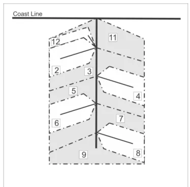
One of the challenges in structuring the drainage system by any coding system is the integration of coastal and continental basins. One solution proposed by Teixeira et al. (2007a), developed using the Brazil’s Pfafstetter System Database, is the integration of coastal basins with continental basins by using the shoreline reference as the integrating element of the drainage system. This ensures that the whole drainage system in different coastal or continental basins is connected. The definition of the coastline is beyond the limit established by the cartographic mapping developed by relevant bodies, because this line does not depend on physical and chemical features, such as salinity, administrative or political issues. Furthermore, this line represents the boundaries of the hydrographic units and therefore interferes directly in the determination of the code of the basin.
Figure 2.4.8 - Example of numbering basins with river delta.
2.4.3 Sink/Spillway
Figure 2.4.9 - Example of coding basin of a sink/spillway.
2.4.4 Water Masses