Ricardo Filipe Chaves Gaspar
Master of Science in Computer Science
Orchestration of a large infrastructure of Remote
Desktop Windows Servers
Dissertation submitted in partial fulfillment of the requirements for the degree of
Master of Science in
Computer Science and Informatics Engineering
Adviser: Paulo Orlando Reis Afonso Lopes, Assistant Professor, Faculdade de Ciências e Tecnologia da Universidade Nova de Lisboa
Co-adviser: Sebastian Bukowiec, IT Systems Engineer,
European Organization for Nuclear Research (CERN)
Examination Committee
Chairperson: Prof. Doutor João Manual dos Santos Lourenço Raporteur: Prof. Doutor José Henrique Pereira São Mamede
Orchestration of a large infrastructure of Remote Desktop Windows Servers
Copyright © Ricardo Filipe Chaves Gaspar, Faculty of Sciences and Technology, NOVA University Lisbon.
The Faculty of Sciences and Technology and the NOVA University Lisbon have the right, perpetual and without geographical boundaries, to file and publish this dissertation through printed copies reproduced on paper or on digital form, or by any other means known or that may be invented, and to disseminate through scientific repositories and admit its copying and distribution for non-commercial, educational or research purposes, as long as credit is given to the author and editor.
This document was created using the (pdf)LATEX processor, based in the “novathesis” template[1], developed at the Dep. Informática of FCT-NOVA [2].
Dedico este trabalho à minha família que me apoiou ao longo desta jornada. Em especial, à minha mãe, Rosa, pelo seu amor e apoio incondicional mesmo à distância. À minha namorada, Ana Sofia, que embarcou comigo nesta aventura, me apoiou e
Ac k n o w l e d g e m e n t s
First, I would like to thank my faculty, Faculdade de Ciências e Tecnologias da Univer-sidade Nova de Lisboa, and the Department of Informatics for the past few years of great teachings and opportunities. A special thanks to Professor Pedro Medeiros, coordinator of the Master degree in Computer Science, for supporting my application for the Technical Student Programme at CERN; and helping me with the needed bureaucracy so I could do my master thesis abroad.
Many thanks to my adviser, Professor Paulo Lopes, without whom it wouldn’t be possible to write this thesis. Thanks for the help with the writing and the support along the way.
Secondly, I want to thank CERN for the opportunity I’ve been given; it was a long-time wish that became true. Of course, this was only possible thanks to my supervisor, Sebastian Bukowiec, who chose me to collaborate with him. I’m grateful for the things he taught me, the freedom and creativity to do my work and write my thesis, and for the great support and encouragement.
I would also like to thank my section leader, Michal Kwiatek, who challenged me to do a small Python project, one that I enjoyed and drove me to learn new things.
Thanks to my co-workers for the interesting conversations, the funny moments and the support.
A b s t r a c t
The CERN Windows Terminal Service infrastructure is an aggregation of multiple virtual servers running Remote Desktop Services, accessed by hundreds of users every day; it has two purposes: provide external access to the CERN network, and exercise access control to certain parts of the accelerator complex.
Currently, the deployment and configuration of these servers and services requires some interaction by system administrators, although scripts and tools developed at CERN do contribute to alleviate the problem. Scaling up and down the infrastructure (i.e., adding or removing servers) is also an issue, since it’s done manually.
However, recent changes in the infrastructure and the adoption of new software tools that automate software deployment and configuration open new possibilities to improve and orchestrate the current service. Automation and Orchestration will not only reduce the time and effort necessary to deploy new instances, but also simplify operations like patching, analysis and rebuilding of compromised nodes and will provide better perfor-mance in response to load increase.
The goal of this CERN project, we’re now a part of, is to automate provisioning (and decommissioning) and scaling (up and down) of the infrastructure. Given the scope and magnitude of problems that must be solved, no single solution is capable of addressing all; therefore, multiple technologies are required. For deployment and configuration of Windows Server systems we resort to Puppet, while for orchestration tasks, Microsoft Service Management Automation will be used.
R e s u m o
O CERN dispõe de uma infraestrutura que designa por “Windows Terminal Service Infrastructure”(WTS), e que é um agregado de servidores (que são, de facto, VMs) que executam os serviços de Remote Desktop e são acedidos diariamente por centenas de utilizadores. Os dois objectivos principais da WTS são: permitir o acesso aos utilizadores credenciados que se encontram off-site, e controlar o acesso ao software que manipula certas zonas do complexo onde se localiza o acelerador de partículas.
Neste momento a implantação (deployment) e configuração de serviços requer alguma interacção por parte dos administradores de sistema - embora com o auxílio de ferramen-tas escriptsdesenvolvidos no CERN. As operações de aprovisionamento e remoção de servidores também requerem alguma interacção, o que contribui para piorar a situação atrás descrita.
Contudo, recentemente têm surgido novas ferramentas que permitem automatizar os processos de distribuição e configuração de software, bem como orquestrar múltiplas ac-tividades desencadeadas sobre múltiplos alvos (por exemplo, servidores). Pode-se, assim, melhorar a qualidade dos serviços prestados pela infraestrutura, já que como resultado da introdução da automação e orquestração pode-se não só diminuir o tempo de apro-visionamento, mas também simplificar operações de patchinge análise e reconstrução de nós problemáticos. Subsidiariamente, pode-se ainda conseguir reagir em tempo útil a aumentos de carga.
O objectivo deste projecto em que estamos inseridos é automatizar o aprovisiona-mento e remoção de servidores e serviços, e a escalabilidade da infraestrutura WTS. Con-siderando o âmbito e a magnitude dos problemas a resolver, não existe uma ferramenta única que, de uma assentada, os permita resolver todos, pelo que é necessário utilizar múltiplas tecnologias: para o aprovisionamento e configuração de sistemas Windows Ser-ver utilizaremos o Puppet; para orquestração de tarefas, vamos usar o Microsoft Service Management Automation.
C o n t e n t s
List of Figures xvii
List of Tables xix
Glossary xxiii
Acronyms xxv
1 Introduction 1
1.1 Context . . . 1
1.2 Motivation . . . 3
1.3 Contributions . . . 4
1.4 Document Organisation . . . 5
2 CERN’s Windows Terminal Service Infrastructure 7 2.1 The infrastructure . . . 7
2.1.1 CERN Cloud Infrastructure (OpenStack) . . . 8
2.1.2 Remote Desktop Services . . . 13
2.1.3 HAProxy . . . 17
2.2 Monitoring the WTS Operations: SCOM . . . 19
2.3 Management and Configuration of the WTS infrastructure . . . 20
2.3.1 Active Directory . . . 20
2.3.2 Group Policy . . . 21
2.3.3 Scripting . . . 22
2.3.4 Computer Management Framework . . . 23
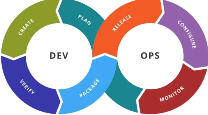
3 Agility 25 3.1 DevOps . . . 25
3.1.1 Before DevOps . . . 26
3.1.2 What is DevOps? . . . 28
3.2 Infrastructure as Code . . . 33
3.2.1 Principles of IaC . . . 34
CO N T E N T S
4 Configuration Management 37
4.1 SCM Tools: an Introduction . . . 37
4.2 SCM Tools: a brief survey . . . 39
4.2.1 Overview . . . 39
4.2.2 Puppet . . . 40
4.2.3 Ansible . . . 50
4.2.4 PowerShell DSC . . . 56
4.3 SCM Tools’ Evaluation . . . 60
4.3.1 Tool Installation and Configuration . . . 60
4.3.2 Testing the Tools . . . 62
4.3.3 Integration with PowerShell DSC . . . 63
4.3.4 Evaluation Results . . . 66
4.4 WTS Configuration Management using Puppet . . . 68
4.4.1 Puppet-wmimodule . . . 69
4.4.2 puppet-sslcertificatemodule . . . 69
4.4.3 cernsslcertificatemodule . . . 71
4.4.4 teigimodule andteigi_subfileresource . . . 73
4.4.5 Building Puppet types from DSC modules . . . 75
4.4.6 WTS Puppet manifests . . . 77
5 Automation and Orchestration 79 5.1 Automation and Orchestration . . . 79
5.1.1 Runbooks and Workflows . . . 80
5.2 Evaluated Automation & Orchestration tools . . . 80
5.2.1 System Center Orchestrator . . . 81
5.2.2 Service Management Automation . . . 83
5.3 Windows PowerShell Workflows Concepts . . . 85
5.3.1 InlineScript . . . 87
5.3.2 Checkpoints . . . 89
5.3.3 Parallel Execution . . . 90
5.4 Service Management Automation usage at CERN . . . 91
5.5 Our Work with the SMA . . . 92
5.5.1 CERNOperations Integration Module . . . 92
5.5.2 Runbookcreate-vm-with-volume . . . 96
6 Conclusions & Future Work 101 6.1 Conclusions . . . 101
6.2 Future Work . . . 103
Bibliography 105
CO N T E N T S
II Ansible test playbook 119
III PowerShell DSC test configuration script 121
IV DSC configuration script to set Group Policy rules 123
V Manifest to set Group Policy rules using DSC resources 125
VI Ansible playbook to set Group Policy rules using DSC resources 127
VII Original version ofpuppet-wmimodule 129
VIII Improved version ofpuppet-wmimodule 131
IX Original version ofpuppet-sslcertificatemodule manifest 133
X Original version of inspect.ps1.erb template 137
XI Original version of import.ps1.erb template 139
XII Improved version ofpuppet-sslcertificatemodule manifest 141
XIII Improved version of inspect.ps1.erb template 145
XIV Improved version of import.ps1.erb template 147
XV cernsslcertificatemodule manifest 149
XVI Windows provider for teigi_subfile 153
XVII Improved teigi_subfile manifest to contemplate Windows systems 157
XVIII Puppet Manifest to configure Remote Desktop Servers of CERN’s WTS 161
XIX Puppet Manifest to configure Remote Desktop License server 167
XX Sync-Files PowerShell script to synchronise a folder structure 169
XXI CERNOperations SMA Integration Module 171
L i s t o f F i g u r e s
1.1 Life cycle of a VM in the WTS infrastructure. . . 5
2.1 Traditional IT vs. Cloud computing service models [21]. . . 9
2.2 OpenStack components [22]. . . 11
2.3 OpenStack & WTS overview (adapted from [17]). . . 12
2.4 Remote Desktop Services Component Architecture. . . 14
2.5 CERN Terminal Service architecture. . . 15
2.6 CERN Windows Terminal Service connection workflow. . . 16
2.7 Remote Desktop Connection to CERN workstation. . . 16
2.8 Load balancing example showing the back-end concept [41]. . . 18
2.9 HAProxy+keepalived example. . . 19
2.10 Active Directory logical structure [51]. . . 21
2.11 Computer Management Framework logical structure [58]. . . 24
3.1 Waterfall model [62]. . . 26
3.2 Evolution of software development (adapted from [63]). . . 27
3.3 DevOps life cycle [68]. . . 31
4.1 Push and pull models [85]. . . 38
4.2 Puppet client-server model [90]. . . 41
4.3 An overview of a puppet run - only steps 2 to 5 (adapted from [97]). . . 48
4.4 Foreman Hostgroup example. . . 50
4.5 Ansible architecture overview [103]. . . 51
4.6 Ansible components [104]. . . 52
4.7 Inventory and playbooks in Ansible [106]. . . 54
4.8 PowerShell DSC push and pull models overview (adapted from [109]). . . 57
4.9 PowerShell DSC execution phase [111]. . . 57
4.10 PowerShell DSC push model [111]. . . 58
4.11 PowerShell DSC pull model [111]. . . 59
4.12 Group Policy GUI displaying the rule to set. . . 64
4.13 Group Policy GUI displaying the settings of the rule to set. . . 65
L i s t o f F i g u r e s
4.15 Cernsslcertificate execution
flowchart. . . 74
5.1 Orchestrator runbook example [133]. . . 80
5.2 Provisioning steps of a VM in the WTS infrastructure. . . 81
5.3 Orchestrator architecture [133]. . . 82
5.4 SMA architecture [14]. . . 84
5.5 SMA runbook execution steps [14]. . . 85
5.6 Execution of PowerShell commands on remote computers using InlineScript [141]. . . 88
5.7 Making a request to OpenStack through AIADM servers. . . 93
5.8 Flowchart of theWaitForVMfunction. . . 94
5.9 Flowchart of theWaitForCMFfunction. . . 95
5.10 Contact CMF Web Service to get the status of a VM’s CMF Agent. . . 95
5.11 Invoking ai-kill to delete Puppet-managed servers on OpenStack. . . 95
5.12 Orchestrating the provisioning process of a VM in the WTS infrastructure. . 96
L i s t o f Ta b l e s
2.1 Subset of CERN’s OpenStack flavours. . . 12
3.1 Conceptual framework characterising DevOps (adapted from [4]). . . 28
3.2 How DevOps addresses different challenges (adapted from [64]). . . . 29
3.3 DevOps practices (adapted from [2]). . . 30
4.1 Foreman Hostgroups. . . 49
4.2 Puppet code and hostgroup organisation. . . 50
4.3 Characteristics of the evaluated SCM tools. . . 61
L i s t o f L i s t i n g s
1 Puppet (hostgroup) manifest example for Windows systems. . . 44
2 Another Puppet (hostgroup) manifest example for Windows systems. . . 46
3 YAML syntax examples [105]. . . 53
4 Example of an inventory file using the INI format. . . 54
5 Example of an inventory file using the YAML format. . . 55
6 Playbook with one play. . . 55
7 Playbook with two plays. . . 55
8 PowerShell DSC configuration script example [112]. . . 60
9 PowerShell DSC configuration script to set a Group Policy rule. . . 65
10 Puppet manifest using a DSC to set a Group Policy rule. . . 66
11 Ansible playbook using a DSC to set a Group Policy rule. . . 67
12 Original version ofpuppet-wmimodule. . . 70
13 Improved version ofpuppet-wmimodule [119]. . . 71
14 Improved version ofpuppet-sslcertificatemodule manifest. . . 72
15 Sample ofcernsslcertificatemodule showing the use of resource collectors. 74 16 Docker file to create a container to build Puppet types from DSC mod-ules [128]. . . 76
17 Sample manifest using DSC resources . . . 77
18 Windows PowerShell Workflow basic structure (adapted from [141]). . . 86
19 Windows PowerShell Workflow calling a function. . . 87
20 InlineScript syntax [141]. . . 87
21 Formatting a new volume in a remote computer using an InlineScript [141]. 88 22 Passing and returning values from an InlineScript activity. . . 89
23 Checkpoint-Workflow example. . . 89
24 An example using the Parallel block. . . 90
25 An example using the Parallel block with a sequence of commands. . . . 91
G l o s s a r y
Ceph Ceph is a software storage platform that implements object storage on a distributed computer cluster and provides interfaces for object-, block- and file-level storage. Ceph aims primarily for completely distributed operation without a single point of failure, scalable to the exabyte level, and freely available.It replicates data and makes it fault-tolerant, using commodity hardware and requiring no specific hard-ware support. As a result of its design, the system is both healing and self-managing, aiming to minimise administration time and other cost [32].
Docker Docker is a software technology providing containers, promoted by the com-pany Docker, Inc. It provides an additional layer of abstraction and automation of operating-system-level virtualisation on Windows and Linux. Docker uses the re-source isolation features of the Linux kernel such ascgroupsand kernelnamespaces, and a union-capable file system (e.g. OverlayFS) to allow independent “containers” to run within a single Linux/Windows instance, avoiding the overhead of starting and maintaining virtual machines (VMs) [79] .
MOF The Managed Object Format (MOF) defined by DMTF is a file format with it’s own language based on IDL (the Object Management Group’s Interface Definition Lan-guage). It provides a way to describe object-oriented class and instance definitions in textual form, with the goals of human readability and parsing by a compiler. The main components of a MOF specification are textual descriptions of element quali-fiers (meta-data about classes, properties, methods, etc.), comments and compiler directives, and the specific class and instance definitions [108].
SOAP Simple Object Access Protocol (SOAP) is a lightweight protocol for exchange of information in a decentralised, distributed environment. It is an XML based proto-col that consists of three parts: an envelope that defines a framework for describing what is in a message and how to process it, a set of encoding rules for expressing in-stances of application-defined datatypes, and a convention for representing remote procedure calls and responses [101].
G LO S SA RY
It provides an API, an in-process workflow engine, and a designer to implement long-running processes as workflows within .NET applications [143].
WinRM Windows Remote Management (WinRM) is the Microsoft implementation of WS-Management Protocol, a standard firewall-friendly protocol that allows hard-ware and operating systems, from different vendors, to interoperate [99].
WMI Windows Management Instrumentation (WMI) is the Microsoft implementation of Web-Based Enterprise Management (WBEM), which is an industry initiative to develop a standard technology for accessing management information in an en-terprise environment. WMI uses the Common Information Model (CIM) industry standard to represent systems, applications, networks, devices, and other managed components. CIM is developed and maintained by the Distributed Management Task Force [55].
Ac r o n y m s
ACL Access Control List.
AD Active Directory.
API Application Programming Interface.
CD Continuous Delivery.
CDev Continuous Development.
CERN Conseil Européen pour la Recherche Nucléaire.
CI Continuous Integration.
CLI Command-line Interface.
CM Continuous Monitoring.
CMF Computer Management Framework.
CPU Central Processing Units.
CT Continuous Testing.
DevOps Development and Operations.
DMTF Distributed Management Task Force.
DSC Desired State Configuration.
DSL Domain Specific Language.
FA Feedback Agent.
GPO Group Policy Object.
GUI Graphical User Interface.
GUID Global Unique Identifier.
AC R O N Y M S
IaaS Infrastructure-as-a-Service.
IaC Infrastructure-as-Code.
IP Internet Protocol.
IT Information Technologies.
LCM Local Configuration Manager.
NIST National Institute of Standards and Technology.
NSS Name System Set.
OS Operating System.
OU Organisation Unit.
QA Quality Assurance.
RDCB Remote Desktop Connection Broker.
RDG Remote Desktop Gateway.
RDL Remote Desktop Licensing.
RDP Remote Desktop Protocol.
RDS Remote Desktop Services.
RDSH Remote Desktop Session Host.
RDVH Remote Desktop Virtualization Host.
RDWA Remote Desktop Web Access.
SaaS Software-as-a-Service.
SCM Software Configuration Management.
SCOM System Center Operations Manager.
SDN Software Defined Network.
SMA Service Management Automation.
SRS Software Requirements Specification.
SSL Secure Sockets Layer.
TDD Test-Driven Development.
AC R O N Y M S
VCS Version Control System.
VM Virtual Machine.
WMF Windows Management Framework.
C
h
a
p
t
e
r
1
I n t r o d u c t i o n
1.1 Context
As one can imagine, an organisation like Conseil Européen pour la Recherche Nucléaire (CERN), whose main goal is to do research in the field of High Energy Physics (HEP) and has more than 16000 employees from 22 countries, requires a huge amount of computing resources to carry out its research and support daily operations - two Data Centres (one in Geneva, Switzerland and another in Budapest, Hungary) with roughly 12,500 physical servers and 25,000 virtualised servers .
This document focuses on CERN’s Windows Terminal Service (WTS), a subset of these computing resources that provides user access to the CERN intranet and controls the access to certain parts of the accelerator complex. The CERN’s WTS is, furthermore, virtualised: its servers are virtual machines (VMs) organised in multiple groups (referred to as clusters) and assigned to different user groups and departments.
Installing, configuring and managing a large number of machines (virtual or not), some of them with quite different configuration parameters, requires a lot of effort from systems administrators (SysAdmins) mainly because there’s a significant amount of hu-man interaction. For example, to deploy a new cluster for, e.g., a CERN department, multiple servers must be deployed, networking must be set up, and several Windows soft-ware components and/or services must be configured. The current approach to minimise the SysAdmin’s work is to use multiple services and tools:
• directory services (Active Directory) - to manage users, groups, computers and other devices;
C H A P T E R 1 . I N T R O D U C T I O N
• scripts - to automate some deployment and configurations tasks;
• configuration management software - to install and/or remove software applica-tions.
CERN’s WTS current management approach relies on the previous mentioned tools plus scripts and an in-house developed configuration management tool, dubbed Computer Management Framework (CMF) (see section 2.3.4) to automate several types of actions; however, there is still a lot of room for improvement.
Unfortunately Windows Server components have distinct interfaces (command line, Graphical User Interface (GUI), Application Programming Interface (API), etc.) which make the scripting approach a possible but tedious solution, as each resulting script deals with a particular component and has little opportunity for reuse. So, one must take a step back and reexamine the problem of Configuration Management.
We begin by stating the obvious: what system administrators want is to have a compli-ant (all the machines in a group have the “same” target software configuration), scalable and easy to manage infrastructure. Therefore, the main objective is the orchestration of common activities by defining workflows to reduce error-prone manual actions and operational workload.
To address this goal, given the size and growth rate of IT infrastructures all over the world, a new paradigm of configuration management was born: Infrastructure-as-Code (IaC) [1], itself a descendant of the Development and Operations (DevOps) paradigm [2–6]. IaC states that configuration management problems can be solved using the same concepts of software development: the idea is to write programs that specify the desired configuration states, and then execute them.
The result is the availability of a number of Software Configuration Management (SCM) [7] tools to tackle these challenges, like Puppet [8], and Chef [9]. The first incar-nation of those tools was targeted at server architectures running UNIX-like operating systems, since they represented the majority when compared to, e.g., Windows. This has been reflected in the way they operate and manage resources since, in UNIX-like systems, most configurations are stored in files and software is installed via packages. Only in recent years these tools have begun to support Windows, and that process is ongoing, with an increased number of features available in every new version of a tool. Windows server deployments (core versions excluded) were mostly based on GUI and their config-uration and management has traditionally required a lot of user interaction. However, in recent versions of Windows Server, many efforts have been made by Microsoft to offer tools like PowerShell extensions (cmdlets, in their terminology) such as Desired State Configuration (DSC) [10] that allow programmers to create scripts that require no user interaction to deploy software packages and configure system components.
1 . 2 . M O T I VAT I O N
Note that automation, as carried out by configuration management software tools, is concerned with a single task (e.g. installing an application, configuring a web server or stopping a service) while orchestration is concerned with the execution of a process or workflow - multiple tasks that can involve multiple systems. An example of a workflow can be setting up an infrastructure for a complex service consisting of several, simpler ones: a web server, an application server and a database server [11].
The usage of automation and orchestration tools may significantly improve the man-agement of large computing infrastructures, as well as reduce the systems administrators’ workload. Some use cases can be alert remediation - monitor a resource and react to a trigger -, maintenance tasks and cross-technology integration1[12]. For Windows Server systems, Microsoft has been releasing products that address those needs, like Orchestra-tor [13] and, more recently, Service Management Automation (SMA) [14].
1.2 Motivation
Within CERN’s Information Technologies (IT) Department, the Applications and De-vices group is the one responsible for the Windows Terminal Service infrastructure which, as referred previously, grants access to servers in the CERN intranet to authorised users. These servers are grouped in clusters which can be categorised in two types: General Purpose (a.k.a. Public) clusters and Specialised (a.k.a. Dedicated) clusters.
There are 3 General Purpose clusters with a total 21 servers which goal is to allow CERN users to remotely log in and use the pre-installed productivity software (Microsoft Office, etc.) and provide access to resources available only in the CERN intranet . The Specialised clusters, for which there are there are 30 (with a total of circa 130 servers), are dedicated to different teams and departments as they serve different purposes related to specific tasks such as accelerator’s experiments, beam monitoring, etc.. A more detailed explanation is described in section 2.1.
The Applications and Devices team must deploy, configure and manage these servers and, currently, a sizeable amount of that work requires human interaction; and, to worsen things up, these tasks must be performed quite often. The challenge, therefore, resides in how to maintain compliance and adherence to CERN’s standards and best practices in a vast, highly dynamic, and growing infrastructure.
In 2011, CERN’s IT Department began to review the data centre infrastructure in order to expand and optimise the its usage [15]. The goal was to explore widely-used tech-nologies for cloud computing, virtualisation, and configuration management to reduce the operational effort, improve agility and support lights-out (i.e., no human presence) remote data centres. Hence, the birth of the CERN’s Agile Infrastructure project [15, 16] which aimed to deploy in CERN data centres, with minimal customisation, the same set of tools and processes for data centre management that was used in data centres elsewhere.
C H A P T E R 1 . I N T R O D U C T I O N
At that time, OpenStack [17, 18] - a software stack that can be used to provide Infrastructure-as-a-Service (IaaS) private clouds- was chosen for CERN data centres. As the IT Department embraced that new paradigm, it was decided that the WTS infrastruc-ture should also be deployed on top of OpenStack.
The reasons for adopting a private cloud infrastructure are manifold, but we will point just two: the sharing of hardware resources (compute, storage and networking) among cloud consumers; and its intrinsic ability to rapidly deploy (and retire) a virtual machine - either through cloning of a base image (a.k.a. template or golden image), or from scratch. In short, WTS servers are Windows Server VMs that can be rapidly deployed with OpenStack; but, after the initial deployment step, further configuration and/or installation of software components must be performed. To automate these tasks, ensure compliance across servers providing the same services and reduce administrator burden, Puppet was chosen.
Since 2013 the Agile Infrastructure is in place and continues to evolve [16] but now, with the introduction of Puppet versions with support for the Windows platform together with Microsoft changes that enable its server tools to be used in non-interactive ways, an opportunity arises to extend those benefits to the Windows Terminal Service infrastruc-ture.
Therefore, our goal is to leverage automation and orchestration across WTS to reduce error-prone manual actions and operational workload. By endowing the infrastructure with automated mechanisms it is possible to reduce both the time to provision new servers and the number of misconfiguration events.
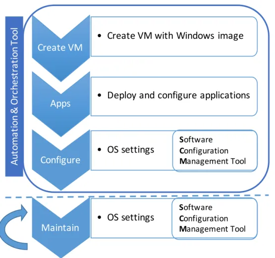
Fig. 1.1 depicts the life cycle of a VM in the WTS showing the steps to provision and maintain it as well as the tools required for these steps. In the next section we will further detail our contributions to the WTS infrastructure including the process illustrated in the fig. 1.1 using the tools previously mentioned.
1.3 Contributions
Our aim is to address the challenges of configuration management, automation and orchestration using an IaC approach in order achieve an automated infrastructure with less operational costs. To reach the above goals, and as there is no single “silver bullet” solution that solves them all, several technologies had to be used together: Puppet for configuration management and SMA for automation and orchestration.
With the adoption of these technologies a reduction has been achieved in the number of operations requiring human (system administrator) intervention for:
• WTS components (servers, software, services) provisioning and decommissioning;
• remedial services (taking a component out and refreshing it or reinstalling it);
1 . 4 . D O C U M E N T O R GA N I SAT I O N
• Create VM with Windows image
Apps
• Deploy and configure applications
Configure
• OS settings
Create VM
Au
to
m
a
ti
o
n
&
O
rc
h
e
st
ra
ti
o
n
T
o
o
l
Maintain
• OS settings
S
oftware
C
onfiguration
M
anagement Tool
S
oftware
C
onfiguration
M
anagement Tool
Figure 1.1: Life cycle of a VM in the WTS infrastructure.
As a result of the use of Puppet for configuration management of the WTS VMs (Windows servers), a number of improvements were made to some Puppet community modules targeted to Windows systems, namelypuppet-sslcertificateandpuppet-wmi, and also to modules privately used at CERN, such ascernsslcertificateandteigi.
Other contributions were made as a result of using Service Management Automation -the automation and orchestration tool. A PowerShell module namedCERNOperationswas developed to abstract the most common operations invoked by other SMA runbooks (e.g. Delete VM, Delete Volume, Wait for VM, Wait for CMF, etc.). Another major contribution was a runbook to orchestrate the provisioning of a WTS VM, following the steps depicted on fig. 1.1.
1.4 Document Organisation
The remainder of this document is organised as follows:
C H A P T E R 1 . I N T R O D U C T I O N
managed.
Chapter 3 starts by describing the birth of DevOps and explains the concepts asso-ciated with it, as configuration management technologies play an important part in this paradigm, one that relies on automation and collaboration between development and operations teams to deliver properly configured infrastructures to run applications and services. It also introduces the motivations for the existence of tools that automate the configuration of large infrastructures.
Chapter 4 starts with a brief introduction of SCM tools, and then presents and de-scribes some of the tools available to increase the level of automation in WTS and makes a comparison between them. It concludes by presenting the work done using Puppet, the tool that was selected to configure and manage the WTS infrastructure.
Then, Chapter 5 begins with the introduction of a set of tools that were selected as candidadtes for automation and orchestration of the WTS infrastructure, followed by a more detailed presentation of the SMA and how it was used to develop workflows to automate the provisioning of servers and execution of maintenance tasks.
C
h
a
p
t
e
r
2
C E R N ’s Wi n d o w s Te r m i n a l Se r v i c e
I n f r a s t ru c t u r e
CERN’s Windows Terminal Service (WTS) infrastructure has two major purposes: pro-vide access to the CERN network from the outside and control the access to certain parts of the accelerator complex. This chapter presents the WTS architecture and the soft-ware technologies that CERN’s IT Department is currently using to deploy, configure and manage WTS hosts and services.
2.1 The infrastructure
The WTS is an infrastructure of virtualised hosts that, for the sake of simplicity of this document, are grouped into two categories that we shall refer to asinfrastructure services (e.g., proxy, broker and licensing hosts) anduser services(i.e., hosts that are accessed by users to run applications, etc.). Hosts running user services are grouped in clusters and assigned to different user groups and departments at CERN; they all run the Windows Server operating system and allow incoming remote connections in order to provide the same user experience as if they were accessed locally. Remote access to a Windows Server host can be enabled through the activation of a server role - a software service embedded in the operating system - called Remote Desktop Services [19].
With RDS, users can access resources in CERN’s internal network using a secure connection without providing direct access to these resources, i.e., the user’s computer (accessing the remote server’s desktop) has no access to the internal resources but the user, indirectly through the remote server, can access those resources. A more detailed description can be found in section 2.1.2.
C H A P T E R 2 . C E R N ’ S W I N D OWS T E R M I N A L S E RV I C E I N F R A S T R U C T U R E
Public clusters (for which there are three, with a total of 21 servers) allow any user with a valid CERN account to log in and use one of the available hosts; these hosts are pre-installed with productivity software (Microsoft Office, etc.) and enable users’ access to resources available only in the CERN intranet (e.g. documents in file servers, internal websites).
Dedicated clusters (for which there are 30, with a total of circa 130 servers) have different purposes, since they are assigned to different groups at CERN and their access is restricted (e.g. monitoring services for the experiments). Each cluster (i.e., its member servers) requires its own software stack since they have different purposes. Only users that are members of a group can access the group’s dedicated cluster(s).
In public clusters, servers accessed by the users are pre-installed and ready-to-use, while servers in dedicated clusters are handed out to group/team managers and assigned administrative privileges that let them deploy new software. Nevertheless, the hosts in the dedicated clusters also have to follow general rules and polices that are in place to ensure a compliant and secure infrastructure.
Gateway servers are also a part of CERN’s WTS; they run a service that enables users to remotely connect directly to their (physical) workstations. In this case, users can remotely work on their workstations located at CERN in the same way they would do if they were in their office.
Given the size of this infrastructure, it makes sense to have tools that automate the deployment and configuration, and provide mechanisms that (re-)apply configuration parameters (either because they have been inadvertently or maliciously altered or because a new configuration must be pushed).
The remaining subsections describe the technologies that are in place to support the WTS infrastructure, and how they are used.
2.1.1 CERN Cloud Infrastructure (OpenStack)
As previously mentioned, our WTS is run as a virtualised infrastructure where the VMs are executed on top an IaaS private cloud; therefore, we would like to start introducing two concepts - cloud computing and IaaS - quoting the National Institute of Standards and Technology (NIST) definitions (the bold markup being ours):
“Cloud computing is a model for enabling ubiquitous, convenient,on-demandnetwork access to a shared poolof configurablecomputing resources (e.g., networks, servers, storage, applications, and services) that can berapidly provisioned and released with minimal management effort or service provider interaction.” ([20])
2 . 1 . T H E I N F R A S T R U C T U R E
consumer usually interacts with the cloud software through portals and requests services (e.g., in a IaaS - see below - service model, the consumer asks for a Virtual Machine (VM) with some characteristics); the provider manages the cloud resources (physical infrastructure, software, etc.) and makes them available to consumers.
Among the different types of service models provided by clouds (see fig. 2.1), the most basic is the Infrastructure as a Service (IaaS). In IaaS, “the capability provided to the consumer is to provision processing, storage, networks, and other fundamental computing resources wherethe consumer is able to deploy and run arbitrary software, which can include operating systems and applications. The consumerdoes not manage or control the underlying cloud infrastructurebut has control over operating systems, storage, and deployed applications.” ([20])
Figure 2.1: Traditional IT vs. Cloud computing service models [21].
The main reasons for using a virtualised, cloud-based infrastructure relates to the flexibility and efficiency it provides: existing hardware may be more efficiently used since it is possible to have multiple VMs per physical host with just a small increase in power usage; and resource sharing is what gives the flexibility for this approach, since it provides the means to allocate resources to those who need them (e.g., new VMs are created) and deallocate/recall them from those which need less, or do not need them anymore (e.g., some VMs are destroyed).
C H A P T E R 2 . C E R N ’ S W I N D OWS T E R M I N A L S E RV I C E I N F R A S T R U C T U R E
VMs for CERN’s Windows Terminal Service are hosted in the Meyrin site (Geneva DC). OpenStack is composed by a set of independent community projects which provide different services and are coupled together to assemble a private cloud infrastructure. Their independence comes from the fact that they can be updated independently, thus having different versions, and not all are required to build a cloud infrastructure. These projects can be also designated as components or services interchangeably. OpenStack features the following main components/projects (adapted from [22]):
• Compute (a.k.a. Nova) allows the user to create and manage a large number of VMs using a set of predefined images. It is the “brain” of the cloud. Nova facili-tates this management through an abstraction layer that interfaces with supported hypervisors.
• Block Storage (a.k.a. Cinder) provides persistent block storage for compute in-stances (VMs). Cinder creates software-defined storage via abstraction by virtual-ising pools of block storage from a variety of back-end storage devices which can be either software implementations (e.g. Ceph) or traditional hardware storage products. Cinder’s primary functions are to manage the creation, attaching and detaching of the block devices. The consumer requires no knowledge of the type of back-end storage equipment or where it is located [24]. This flexible architecture makes creating and managing block storage devices very easy.
• Networking (a.k.a. Neutron)provides various networking services to cloud users (tenants) such as IP address management, DNS, DHCP, load balancing, and security groups (network access rules, like firewall policies). It also provides a framework for Software Defined Networks (SDNs) that allows for pluggable integration with various networking solutions. Neutron allows cloud tenants to manage their guest network configurations. Security features include network traffic isolation, avail-ability, integrity and confidentiality.
• Image Service (a.k.a. Glance)provides disk image management services: image discovery, registration, and delivery to the Compute service, as needed. Users can upload and discover data assets that are meant to be used with other services. This currently includes VM images and metadata definitions. Glance has a RESTful API that allows querying of VM image metadata as well as retrieval of the actual image.
2 . 1 . T H E I N F R A S T R U C T U R E
offers an Amazon Web Services S3 compatible API. Swift provides a high degree of resiliency through data replication and can handle petabytes of data.
• Identity Service (a.k.a. Keystone)provides a central directory of users mapped to the OpenStack services. It is used to provide an authentication and authorisation service for other OpenStack services.
• Dashboard (a.k.a. Horizon) is a web-based portal that interacts with all the un-derlying OpenStack services such as Nova, Neutron, etc. Through this interface cloud administrators and tenants (users) can provision, manage, and monitor cloud resources.
Figure 2.2: OpenStack components [22].
CERN’s OpenStack infrastructure has all components deployed, with the exception of Swift and a few others not referred here (e.g. Ceilometer and Heat) [18].
As previously described, OpenStack Nova supports multiple hypervisors [25], such as KVM [26], Xen [27], Hyper-V [28] and VMWare ESXi [29]. For the sake of comprehension, it’s important to introduce here the concept of hypervisor: an hypervisor is a software module that abstracts (virtualises) hardware resources and multiplexes and manages them so that multiple Operating Systems (OSs) can run simultaneously on the same physical computer. Bugnion et al. [30] define an hypervisor as a specialised piece of system software that manages and runs virtual machines; the concept was first introduced by Popek and Goldberg [31].
Nowadays, WTS VMs are run on top of the KVM hypervisor as KVM’s current versions also support Windows guests; previously, both KVM (for Linux guests) and Hyper-V (for Windows guests) were used, but after some time CERN’s OpenStack team chose to adopt one hypervisor only, because that simplifies the development and management.
C H A P T E R 2 . C E R N ’ S W I N D OWS T E R M I N A L S E RV I C E I N F R A S T R U C T U R E
Figure 2.3: OpenStack & WTS overview (adapted from [17]).
Table 2.1: Subset of CERN’s OpenStack flavours.
Name Memory (MB) Disk (GB) vCPU’s (Cores)
m2.small 1875 10 1
m2.medium 3750 20 2
m2.large 7500 40 4
m2.xlarge 15000 80 8
m2.2xlarge 30000 160 16
In WTS, all Windows VMs use the m2.xlarge flavour since it provides enough disk space to store the Windows operating system, and also sufficient CPU and memory re-sources to execute it. The use of more generous flavours is possible, but due to the amount of resources they require, it’s often difficult to find available resources to allocate. In ad-dition, the large number of VMs already used for WTS is continuously growing and the team responsible for WTS infrastructure has adopted a horizontal scaling (having more machines) approach as opposed to vertical scaling (have less machines but with more resources) to ensure a good availability and quality of service.
OpenStack images (a.k.a golden images or templates) are managed through Glance, but stored on a Ceph [32] back-end. When an image is chosen to start a VM, the instance’s (virtual) system disk is created locally on the host that is going to execute the VM; the host’s local storage for those disks is based on SSD technology. However, if the instance needs more storage, that space is assigned as a new disk volume, with a custom size; usually additional volumes are crafted from Ceph’s HDD-based storage pools.
2 . 1 . T H E I N F R A S T R U C T U R E
Note: The purpose of this document is not to describe the OpenStack-based CERN’s private cloud in detail, but rather describe how the cloud is used to host the different types of (virtual) servers that are used to build the WTS infrastructure. For a more detailed description of OpenStack, see [22]. To learn more about CERN’s OpenStack private cloud, see [18, 33–36].
2.1.2 Remote Desktop Services
Microsoft’s Remote Desktop Services (RDS) [19] are implemented in a role included in Windows Server; when enabled, it allows remote connections to access and control Windows machines over the network. Previous to Windows Server 2008 R2 the role was named Terminal Services; CERN’s IT Department has kept the original name, hence the WTS acronym: “CERN Windows Terminal Service”.
Note:Throughout this document the service provided by the IT Department at CERN will be referred to as “CERN’s Windows Terminal Service” but, for the sake of convenience, “Remote Desktop Services Infrastructure” or, in short, “RDS Infrastructure” will also be
used to refer to an infrastructure running these services.
RDS uses the Remote Desktop Protocol (RDP) [37, 38] to establish connections between clients and servers, enabling users to connect to remote computers and interact with them as if they were “right there”, at the user’s desk where the computer is located. Users can connect to remote computers using thin-client applications such as Remote Desktop Connection or RemoteApp.
In RDP, a client receives the (screen) image of the remote system’s desktop, displays that image locally, and sends the input from the local mouse and keyboard back to the remote system, which receives that input and responds accordingly, as if the input was coming from directly connected devices. As a result, all execution takes place on the remote system.
Figure 2.4 depicts the six fundamental components of the Remote Desktop Services architecture (the Server Manager is not a part of it, it’s just a management console included in Windows Server systems).
• Remote Desktop Session Host (RDSH):formerly named Terminal Server, enables a server to host remote desktop sessions. Users can connect to an RDSH server to execute programs, manage files and use network resources on that server. The access can be performed through the Remote Desktop Connection client.
C H A P T E R 2 . C E R N ’ S W I N D OWS T E R M I N A L S E RV I C E I N F R A S T R U C T U R E
Remote Desktop Web Access
Remote Desktop Gateway
Remote Desktop Licensing
Remote Desktop Session Host Component Architecture
Server Manager
SQL Database
Remote Desktop Connection
Broker
Remote Desktop Virtualization Host
Figure 2.4: Remote Desktop Services Component Architecture.
new connection, the Connection Broker redirects the user to the same Session Host server; this prevents the user from being connected to a different server in the farm, thus starting a new session.
• Remote Desktop Web Access (RDWA):once named Terminal Server Web Access, allows users to make Remote Desktop connections to remote servers using a web browser.
• Remote Desktop Gateway (RDG):formerly named Terminal Server Gateway, en-ables authorised users to connect to resources on an internal corporate network over the Internet or on the same network. The network resources can be RDSH servers running virtual desktops, or physical computers with Remote Desktop Services enabled.
• Remote Desktop Licensing (RDL):named Terminal Server Licensing in the past, manages the Remote Desktop Services client access licenses (RDS CALs) that are required for each device or user to connect to an RDSH server. It is used to install, issue, and track the availability of CALs on a Remote Desktop license server. It only allows remote connections if there are licenses available, otherwise they are rejected.
2 . 1 . T H E I N F R A S T R U C T U R E
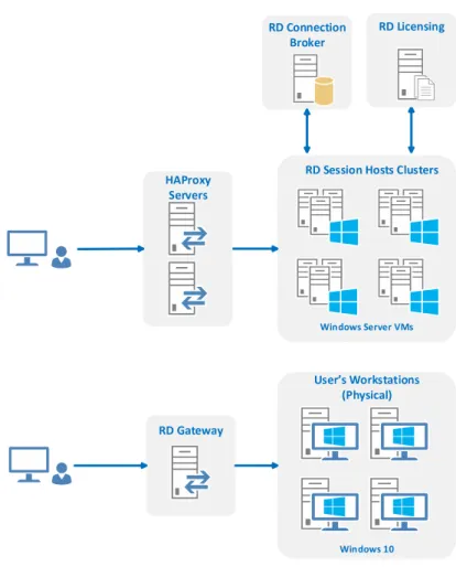
The above is just a general description of RDS; CERN’s Windows Terminal Service infrastructure has a somewhat different structure, illustrated in fig. 2.5 for two use cases: the first scenario (the upper-half of the figure) shows how remote desktop connections to public/dedicated servers are dealt with; the second portrays remote desktop access to physical Windows 10 workstations, placed in user’s desks.
Figure 2.5: CERN Terminal Service architecture.
In the first scenario (see fig. 2.6), a cluster of HAProxy [39, 40] servers running on top of Linux VMs, acts both as a proxy and a load balancer for the RDP traffic, effectively replacing RDCB which is used in CERN’s WTS just to keep track of user sessions. When a remote desktop connection, initiated at the user’s client (1) reaches one HAProxy server, the load balancer chooses one of the RDSH servers (2) to try to establish the remote desktop connection. To do that, the chosen RDSH server has to request a license from RDL (3) and then ask if the RDCB has any connection state for that user (4); if one is found, the session is resumed; if not, a new session is created. Afterwards (5), the remote desktop connection is established.
C H A P T E R 2 . C E R N ’ S W I N D OWS T E R M I N A L S E RV I C E I N F R A S T R U C T U R E
Figure 2.6: CERN Windows Terminal Service connection workflow.
made to RDG (1), which validates if there are licenses available to accommodate a new connection (2) and then establishes the connection (3).
Figure 2.7: Remote Desktop Connection to CERN workstation.
In both scenarios, the only components exposed to the outside network are HAProxy and Remote Desktop Gateway servers. Even though it is not depicted, there is a firewall between the HAProxy/RDG and the external network, for enhanced security.
It is also important to refer why a (Windows) Server version is used for the user-accessible (i.e., running RDSH server role) hosts, instead of the usual desktop versions (e.g. Windows 7,8,10). The reason has to do with the ability to allow multiple Remote Desktop sessions at the same time: only server versions allow them.
2 . 1 . T H E I N F R A S T R U C T U R E
2.1.3 HAProxy
HAProxy [39, 40] stands for “High Availability Proxy”, an open source software that is both a proxy server and a load balancer that can be run on Linux, Solaris, and FreeBSD. It has been designed for scenarios where availability is an important requirement, i.e., down times should be short (a few minutes, at most). It is capable of load balancing and proxying TCP and HTTP-based traffic and also has monitoring capabilities. It’s used by many high-profile websites including: GitHub, Stack Overflow and Twitter.
HAProxy uses two concepts to deal with the services (e.g., webservers/applications) it mediates access to: back-end and front-end.
• Aback-endis a set of servers that receives forwarded requests and is defined by the load balancing algorithm to use and a list of servers and ports.
• Afront-enddefines how requests should be forwarded to back-ends. Their defini-tions are composed by a list of Internet Protocol (IP) addresses and ports, ACLs and back-end rules. A front-end can be configured to various types of network traffic.
HAProxy can be considered a fairly complete load balancer regarding the set of al-gorithms it supports (9 different load balancing algorithms) [40]. The most common are:
• round-robin- for short connections, pick each server in turn;
• leastconn- for long connections, chose the least recently used of the servers with the lowest connection count;
• source- for SSL farms (groups of servers) or terminal server farms, where the server directly depends on the client’s source address;
• uri- for HTTP caches, the server directly depends on the HTTP URI;
• hdr- the server directly depends on the contents of a specific HTTP header field;
• first- for short-lived virtual machines, all connections are packed on the smallest possible subset of servers so that unused ones can be powered down.
In the WTS infrastructure theleastconnalgorithm is used to ensure a good load balance of RDS sessions (long connections).
C H A P T E R 2 . C E R N ’ S W I N D OWS T E R M I N A L S E RV I C E I N F R A S T R U C T U R E
Figure 2.8: Load balancing example showing the back-end concept [41].
RDS session can be recorded, enabling requests (from same client) to be redirected to the same server.
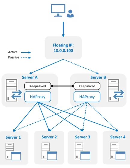
High Availability for the HAProxy: Keepalived
CERN uses the Keepalived [42] software to monitor services or systems for failures and, upon failure, restarts the failed service/server - in a different node, if needed.
Keepalived uses a floating IP address that can be moved between servers. In the case of two servers, for example, if the primary server goes down, the floating IP will be automatically moved to the second server, allowing it to resume the service with the same IP, thus keeping it transparent to clients [43]. An example diagram showing the usage of Keepalived with two HAProxy servers is depicted in figure 2.9.
CERN Windows Terminal Service has two HAProxy servers monitored by keepalived to provide a highly available and redundant infrastructure, eschewing a single point of failure.
Feedback Agent
Feedback Agent (FA) [44, 45] is a daemon designed to run on back-end servers that provides a way for HAProxy to get their workload status (CPU and memory usage percent-age). HAProxy servers can take into account the server’s workloads and redirect traffic to those which are less loaded.
This agent has three modes: normal, down and drain. Normal, means that the server can receive connections; Down, means the server stops all the connections and doesn’t accept new ones; Drain, server doesn’t accept new connections, current connections are kept until they are terminated.
2 . 2 . M O N I T O R I N G T H E W T S O P E R AT I O N S : S CO M
Figure 2.9: HAProxy+keepalived example.
2.2 Monitoring the WTS Operations: SCOM
System Center Operations Manager (SCOM) [46] is a comprehensive monitoring solution that offers centralised monitoring and management of applications, virtual environments, physical environments, and cloud-based workloads. SCOM is the core monitoring solu-tion from Microsoft for over a decade and supports both Microsoft Windows Server and Unix-based systems.
SCOM uses a single interface that shows the state, health and performance informa-tion of computer systems, and also provides alerts generated in response to events that may signal problems, e.g., in availability, performance, configuration or security.
C H A P T E R 2 . C E R N ’ S W I N D OWS T E R M I N A L S E RV I C E I N F R A S T R U C T U R E
the scale of the infrastructure, the more challenging this task becomes [47].
In System Center Operations Manager, the administrator can configure what to moni-tor by selecting targets as diverse as computers, devices, services and applications. Some targets may require importing management packs that provide specific agents for the items being monitored.
A SCOM is infrastructure is composed by 4 components [46]:
• Management Server- is the central point for administering the management group and communicating with the database.
• Operational Database - is a SQL Server database that contains all configuration data for the management group and stores all monitoring data that is collected and processed for the management group. It retains short-term data, by default 7 days.
• Data Warehouse Database- is also a SQL Server database that stores monitoring and alerting data for historical purposes. Data that is written to both databases, so reports always contain current data. The data warehouse database retains long-term data.
• Reporting Server- is responsible for generating and presenting reports based on the data stored in the data warehouse database.
In WTS, SCOM is used to monitor availability, workload and health status of servers and databases; SCOM alarms are also used to trigger alerts when some resources are reaching critical status (e.g. not enough free disk space in a particular server).
2.3 Management and Configuration of the WTS infrastructure
As previously referred, the WTS infrastructure is currently configured and managed using services commonly found in Windows domain networks, such as Active Directory and Group Polices (that help manage computing resources like users, computers and printers) and other mechanisms like scripts and configuration management software tools. In this subsection we briefly introduce these services and mechanisms and explain how they are used in CERN’s WTS.
2.3.1 Active Directory
Active Directory (AD) [48] is a directory service that Microsoft developed to centralise management of Windows (domain) networks.
2 . 3 . M A N AG E M E N T A N D CO N F I G U R AT I O N O F T H E W T S I N F R A S T R U C T U R E
security principals (user or computer accounts, and groups). Each object represents a single entity (user, computer, group, or printer) and its attributes.
AD allows clients to find objects within its namespace - the area in which a network component can be located. Using the previous example, phone books provide a names-pace for resolving names to telephone numbers in the same way that DNS is a namesnames-pace that resolves host names to IP addresses. In AD, the namespace is used for resolving the names of network objects to the objects themselves. Namespaces can be organised into multiple hierarchical levels: forest, tree, and domain.
A domain is as a logical group of network objects (computers, users, devices) that share the same AD database, while a tree is a collection of one or more domains into a contiguous namespace.
The forest represents the top of the structure and is a collection of trees that share a common global catalog, directory schema, logical structure, and directory configuration. The forest represents the security boundary within which users, computers, groups, and other objects are accessible.
The objects held within a domain can be grouped into Organisational Units (OUs) allowing to mimic an organisation structure and thus simplifying the implementation of policies and reducing administration burden [49, 50].
Typically, to apply and enforce a set of configurations and polices to same OUs or domains, Group Polices are used, as explained in subsection 2.3.2 below.
Figure 2.10: Active Directory logical structure [51].
2.3.2 Group Policy
C H A P T E R 2 . C E R N ’ S W I N D OWS T E R M I N A L S E RV I C E I N F R A S T R U C T U R E
Group policies are Active Directory objects formally named Group Policy Objects (GPOs) that contain the rules and settings to be applied to an Organisation Unit (OU) or domain. If a set of users needs to have the same standard desktop configuration and the same set of applications, the users can be put into an OU, and Group Policy can then be used to configure the desktop and to manage the installation of applications [50]. There are many types of policy settings available; we list a few below:
Administrative templates Used to manage registry-based parameters for configuring application settings and user desktop settings, including access to operating system com-ponents and to the control panel.
Security Used to manage the local computer, domain, and network security settings, including controlling user access to the network, configuring account policies, and con-trolling user rights.
Software installation Used to centralise the management of software installations and maintenance.
Scripts Used to specify scripts that can be run when a computer starts or shuts down, or when a user logs on or off.
Folder redirection Used to store certain user profile folders on a network server. These folders, such as the My Documents folder, appear to be stored locally but are actually stored on a server where they can be accessed from any computer on the network.
Preferences Used to manage options related to Windows settings or Control Panel set-tings, including drive mappings, environment variables, network shares, local users and groups, services, devices, and many more.
Group Policy allows the SysAdmin to define policies that control software deployment in a very limited form. It is GUI-based, and therefore doesn’t provide an automated way of deploying software, or reporting about its installation status.
2.3.3 Scripting
Scripting is most basic approach when it comes to automate the deployment and con-figuration of operating systems. SysAdmins rely on them to do most of the tedious and repetitive tasks that involve multiple steps in order to obtain the desired effects, while avoiding error prone operations.
2 . 3 . M A N AG E M E N T A N D CO N F I G U R AT I O N O F T H E W T S I N F R A S T R U C T U R E
Until the introduction of PowerShell, Windows SysAdmins had to rely on the system shell and other scripting languages (e.g. JScript [52], VBScript [53]) to automate tasks. However, the system shell cannot be used to automate all facets of the GUI’s functionality, in part because command-line equivalents of operations exposed via the graphical inter-face are limited, and the scripting languages are elementary and don’t allow the creation of complex scripts [54].
In 2006, Microsoft introduced the PowerShell automation and scripting language for the Windows platform, one that allows to simplify the management of these systems [54]. Unlike other text-based shells, PowerShell takes advantage of .NET Framework, providing an object-oriented paradigm and a massive set of built-in functionality for taking control of Windows environments.
PowerShell enables scripts to perform virtually any task one can do using the Win-dows’ GUI; it includes numerous system administration utilities, and has consistent syn-tax and naming conventions, and improved navigation for common management data, such as the registry, certificates stores, and WMI [55] - a core technology for Windows system administration, because it exposes a wide range of information in a uniform man-ner [56]. As described by Microsoft:
“Windows Management Instrumentation (WMI) is the Microsoft implementation of Web-Based Enterprise Management (WBEM), which is an industry initiative to develop a standard technology for accessing management information in an enterprise environment. WMI uses the Common Information Model (CIM) industry standard to represent systems, applications, networks, devices, and other managed components. CIM is developed and maintained by the Distributed Management Task Force (DMTF).” ( [57])
PowerShell provides an interface and programming environment that allows users and administrators to access and set system properties through .NET objects and single-function command-line tools calledcmdletswhich are the building blocks of PowerShell scripts.
A lot of the current automation and configuration effort of WTS is based on PowerShell scripts, due to their flexibility and to the advantages presented above.
2.3.4 Computer Management Framework
The Computer Management Framework (CMF) [58] is a software framework, designed and developed at CERN, that offers a range of tools that enables groups of Windows computers to be easily managed. CMF’s main functionality is to distribute software applications to computers in a user-friendly and managed way; it replaced the Microsoft Systems Management Server (SMS) [59] tool and some group policies and start-up scripts that were previously used.
C H A P T E R 2 . C E R N ’ S W I N D OWS T E R M I N A L S E RV I C E I N F R A S T R U C T U R E
also offers improved security, stricter control on patch deployment and reboot actions, and enables instant reporting.
A domain is called a Name System Set (NSS) in CMF, and the framework is based on the concept of hierarchical delegations between a master NSS (domain) and sub-domains. The master NSS has full control over the whole domain and can create other NSSs and grant them permissions; the idea is to structure NSSs in a way so that each NSS can control a well defined set of computer or user groups. The role for each NSS is defined by the permissions that were granted by the master NSS.
C
h
a
p
t
e
r
3
Ag i l i t y
This chapter is about agility; agility is of paramount importance today, not only in development but also in operations, as only after deployment the new product or version can be used and appreciated.
Introduction of agility in the development process is generally acknowledged to have happened around the year 2000 (although some trace it back into the 70s and Smalltalk) but, as far as infrastructure operations are concerned, that process is very recent.
In this chapter we start by introducing DevOps, which has merged agile software development with agile infrastructure operations and then explain how the later was a result of the adoption of the Infrastructure-as-Code (IaC) paradigm in the new tools that are now in place.
3.1 DevOps
C H A P T E R 3 . AG I L I T Y
3.1.1 Before DevOps
Before agile development methodologies were adopted, the traditional approach of developing software was based on the Waterfall model [60], which was first formally defined by Winston W. Royce in 1970 - although he didn’t use the term “waterfall”. In the Waterfall model, the whole process of software development is divided in distinct phases which are carried out sequentially - a phase only starts when the previous one has ended. Phases in Waterfall model are [61]:
1. Requirement Gathering and Analysis- All possible requirements of the system to be developed are gathered and documented in a Software Requirements Specifica-tion (SRS) document.
2. System Design- The requirement specifications from first phase are studied and the system design is prepared. This system design helps in specifying hardware and system requirements and helps in defining the overall system architecture.
3. Implementation- Based on system design, the system is first developed in small programs called units and then integrated in the next phase. Each unit is developed and tested for its functionality, a.k.a. Unit Testing.
4. Integration and Testing - All the units developed in the implementation phase are integrated into a system after testing of each unit. Post integration, the entire system is tested for any faults and failures.
5. Deployment- Once the functional and non-functional testing are done, the product is deployed in the customer environment or released to the market.
6. Maintenance- After deployment, usually there are some issues which come up in the customer environment. Hence, patches or new versions are released in order to enhance the system. Maintenance is the delivery of changes to the customer environment.
3 . 1 . D E VO P S
This model is simple and easy to understand and implement: each phase has to be completed in sequence, and has specific deliverables (documents, tests, code); and this approach is quite suitable for small projects where the requirements are very well defined and understood.
But the waterfall model is not suitable for projects whose requirements are subject to frequent change and when the final software/product is not clear; it is also not suitable for projects that require large-scale infrastructures - the waterfall model was not designed to cope with uncertainty and frequent changes: once in a testing phase, is very difficult to go back and change something that was not very well thought in the design phase.
In recent years, big software projects and large-scale infrastructures are more common and it’s hard to design and develop software using models that don’t cater for unforeseen changes. Adopting such a model would be designing to failure, increasing the costs of such projects. On the other hand, the Agile development model, an approach that results in faster software development, incorporates design changes and relies on small but frequent releases of new features.
However, this approach raises lots of conflicts between the development and opera-tions teams: developers want to deliver new functionalities as soon as they have them, following an Agile development model, while operators resist against new changes as they are afraid of disrupting production services. Operations teams usually have plenty of responsibilities in addition to software deployment, including managing costs, user accounts and overall capacity, and ensuring overall security [6]. Continuous integration and testing teams served as a buffer between the other two groups, thus avoiding some conflicts, but a better solution was the introduction of the DevOps approach, something that we will study in more detail further down.
Figure 3.2: Evolution of software development (adapted from [63]).
So, in order to achieve frequent delivery of small software changes, a new set of tools and techniques was needed. The new set of tools that was created was heavily influenced by two concepts: Infrastructure as Code (IaC) and Software Configuration Management (SCM) [6].
![Figure 2.1: Traditional IT vs. Cloud computing service models [21].](https://thumb-eu.123doks.com/thumbv2/123dok_br/16525292.735973/37.892.144.748.469.800/figure-traditional-vs-cloud-computing-service-models.webp)
![Figure 2.2: OpenStack components [22].](https://thumb-eu.123doks.com/thumbv2/123dok_br/16525292.735973/39.892.160.737.461.647/figure-openstack-components.webp)
![Figure 2.3: OpenStack & WTS overview (adapted from [17]).](https://thumb-eu.123doks.com/thumbv2/123dok_br/16525292.735973/40.892.174.723.152.379/figure-openstack-amp-wts-overview-adapted.webp)

![Figure 2.10: Active Directory logical structure [51].](https://thumb-eu.123doks.com/thumbv2/123dok_br/16525292.735973/49.892.229.663.681.977/figure-active-directory-logical-structure.webp)
![Figure 2.11: Computer Management Framework logical structure [58].](https://thumb-eu.123doks.com/thumbv2/123dok_br/16525292.735973/52.892.140.764.362.619/figure-computer-management-framework-logical-structure.webp)