FACULDADE DE CIÊNCIAS
DEPARTAMENTO DE ENGENHARIA GEOGRÁFICA, GEOFÍSICA E ENERGIA
Analysis of a District Energy system containing Thermal
Energy Storage and Heat Pumps
Fábio Emanuel Lourenço Batista
Mestrado Integrado em Engenharia da Energia e do Ambiente
Dissertação orientada por:
Prof. Dr. Guilherme Carrilho da Graça
In the context of meeting the targets set by 2050 for reducing greenhouse gas emissions, District Energy (DE) systems are considered to be a proven solution. This is essentially due to their ability to re-use energy that would otherwise be wasted, and its compatibility with a variety of other technologies, such as Thermal Energy Storage (TES) and renewable energy sources. When available, thermal energy storage provides greater flexibility, reliability, as well as energy security and it can be used to optimize equipment responsible for thermal energy production, as for instance, heat pumps.
The main objective of this project is to study the influence of the introduction of short-term thermal storage in a DE, where heat and cold requirements are supplied by a combination of seasonal TES and heat pumps. To be specific, the focus is to analyze to what extent can short-term TES be used to shift the heat pumps electrical heating loads, from peak to off-peak periods, and quantify the influence of this strategy on energy production and electricity consumption.
In order to do this, space heating and cooling demand data regarding a group of buildings is determined in Dymola/Modelica, and the energy systems performance is evaluated by using an analytical MATLAB model. The results obtained show that the introduction of short-term storage allowed to shift some of the thermal load from peak to off-peak periods. This operation led to a significant reduction in the individual electricity costs for the heat consumers (11.5% to 37.5%), which were determined based on electricity prices from the Dutch EPEX day-ahead spot market. Regarding electricity consumption and total heat production, it was noticed that the introduction of short-term storage led to an increase in the total heat output from heat pumps (~7%), mainly due to higher thermal losses. However, the global heat pumps coefficient of performance (COP) also increased (~14%), which resulted in less electricity consumption (~-13%), despite of the higher heat production.
Keywords: District Energy, Seasonal Thermal Energy Storage (STES), Short-term Thermal Energy
No contexto de atingir as metas estabelecidas até 2050 para a redução da emissão de gases de efeito de estufa, as redes urbanas de energia são já consideradas uma solução provada. Isto deve-se esdeve-sencialmente ao facto de estas possibilitarem recuperar energia que deve-seria de outra forma desperdiçada. Para além disso, possibilitam a integração de diferentes fontes de energia renovável, ou outras tecnologias, como é o caso de armazenamento térmico de energia. Quando presente, armazenamento de energia térmica confere maior flexibilidade, bem como maior segurança energética e pode ser usado para otimizar o equipamento responsável pela produção de energia térmica, como por exemplo bombas de calor.
O principal objetivo deste projeto é estudar a influencia da introdução de armazenamento de energia térmica de curta duração numa rede urbana de energia, em que o abastecimento de calor é suprido por uma combinação de armazenamento de energia térmica sazonal e bombas de calor. Em particular, pretende-se analisar de que forma pode o armazenamento de curta duração, que consiste num tanque de água, ser usado para deslocar a produção de calor (carga térmica), de períodos de cheia ou ponta, para períodos de vazio, e quantificar as consequências desta estratégia (load shifting) na produção de energia térmica e consumo de eletricidade.
Para que isto seja possível, o consumo de energia relacionado com aquecimento e arrefecimento de um grupo de edifícios é determinado usando um modelo implementado em Modelica, e a análise dos sistemas de energia é feita através de um modelo analítico, implementado em Matlab. Os resultados obtidos mostram que a introdução de armazenamento térmico de curto prazo, permitiu deslocar parte da carga térmica de períodos de pico, para períodos de vazio. Isto levou a uma redução significativa (11.5% a 37.5%) nos custos individuais de eletricidade para os consumidores de calor, que foram determinados com base nos preços de mercado de eletricidade holandês (EPEX), e em tarifas de distribuição e transmissão. Paralelamente, verificou-se um aumento na produção total de calor (~ 7%), principalmente devido a maiores perdas térmicas face ao sistema sem armazenamento de curta duração. No entanto, a eficiência global das bombas de calor (COP) também aumentou (~ 14%), o que resultou ainda assim num menor consumo global de eletricidade (~ -13%), apesar da maior produção de energia.
Palavras-Chave: Redes Urbanas de Energia, Armazenamento térmico de curta duração, Armazenamento
Table of contents
Chapter 1 - Introduction ... 1
1.1. Scope and Method ... 2
1.2. Thesis outline ... 3
Chapter 2 - District Energy Systems ... 5
2.1. Heat and cold Generation ... 6
2.1.1. Heating systems ... 6
2.1.2. Cooling systems ... 10
2.2. Heat and Cold Distribution ... 12
2.3. Heat and Cold Consumption ... 13
2.4. Final remarks ... 15
Chapter 3 - Energy Storage ... 17
3.1 Electrical Energy Storage ... 18
3.2 Thermal Energy Storage ... 19
3.2.1. Short-term thermal storage ... 21
3.2.2. Seasonal thermal storage ... 24
3.3. Combination of TES and Heat Pumps ... 26
Chapter 4 - Case Study and System Configurations ... 29
4.1. Neighborhood case study ... 29
4.2. System Configurations ... 30
4.3. Simulation software tools ... 31
Chapter 5 - Implementation in Dymola and MATLAB ... 33
5.1. Heating and Cooling Demand ... 33
5.1.1. Occupant’s behavior and other inputs ... 36
5.2. Heat and Cold Generation ... 37
5.2.1. Heating System ... 37
5.2.2. Cooling system ... 41
5.3. Thermal Energy Storage ... 43
5.4. Heat and Cold Distribution ... 47
5.4.1. Hydraulic Considerations ... 47
5.4.2. Thermal Considerations ... 48
5.5. Complete system and final remarks ... 49
Chapter 6 - Results and Discussion ... 51
References ... 59
Appendix A - Neighborhood Case Study Related Inputs ... 63
Appendix B - MATLAB relevant code ... 67
I – Main functions ... 67
Heating ... 67
Reference Case ... 67
System 1 (Short-term storage at each building) ... 69
System 2 (Centralized heat production and storage) ... 72
Cooling ... 73
II – Secondary functions ... 75
Thermal losses Pipe ... 75
Hydraulic Power (pumping) ... 76
Enthalpy ... 77
Soil temperature (Kusuda model) ... 78
Figure index
Figure 1.1 - World primary energy consumption: (left) per source in Mtoe, 1990 – 2015; (right) Share per source in 2015. [3]... 1 Figure 1.2 - Share on Final Energy consumption per sector in Europe, 2015.[6] ... 1 Figure 2.1 - Historical development of district energy networks, to the modern day and into the future. [9] ... 6 Figure 2.2 - COP of water-to-water heat pumps according to the heating capacity range. The numbers above red bars represent number of units reported. [21] ... 8 Figure 2.3 - Partial load factor vs. partial load ratio for water-to-water HP. [21] ... 9 Figure 2.4 – Existing district network in Amsterdam, and sources of unused heat. [8] ... 10 Figure 2.5 – Types of district energy networks: (a) Radial systems; (b) Ring networks; (c) Meshed networks. [33] ... 12 Figure 2.6 - Daily distribution of sensible and latent cooling loads for an apartment building in Hong Kong. [41] ... 14 Figure 3.1 - Principal electrical energy storage technologies [44] ... 18 Figure 3.2 - Thermal energy storage categories, according to criteria relevant to this project. ... 19 Figure 3.3 – Left - Temperature and stored heat for a solid-liquid phase change, compared with sensible heat [53]; Right - Classes of materials that used as PCMs and their typical range of phase change temperatures and melting enthalpy [54]. ... 20 Figure 3.4 - Breakdown of electricity consumption among residential end-use equipment in EU-15 (black slices represent electricity consumption for heating and cooling that can be managed by TES) [45]. ... 22 Figure 3.5 - Strategies for peak shifting: (I) partial-storage load leveling; (II) partial-storage demand limiting and (III) full storage [57]. ... 23 Figure 3.6 - Schematic representation of common technologies for seasonal thermal energy storage. [59] ... 24 Figure 3.7 - Schematic representation of an ATES system operation when combined with heat pump: (left) – heat injection and cold extraction (Summer); (Right) – heat extraction and cold injection (Winter) [63]. ... 26 Figure 4.1 - Neighborhood case-study layout. ... 29 Figure 4.2 – Configurations used to supply the space heating and cooling requirements of the neighborhood considered in this project. Adapted from [19] and [52]. ... 30 Figure 4.3 – Chain of the described global methodology. ... 32 Figure 5.1 - Schematic view of the RC building model in Dymola (initial approach). ... 34 Figure 5.2 – Model structure in Dymola: (left) is the bottom layer, and (right) is the top layer. The dark blue lines refer to internal gains and controls, blue represent fluids, red heat transfer, and yellow weather data. Source: [70] ... 35 Figure 5.3 – MixedAir model from Buildings library: (a) – Icon layer view. (b) – Diagram layer view. Source: [70] ... 35 Figure 5.4- Top: Calculated supply (red) and return (blue) water temperatures for the first 48h of the simulated year, using S1 building typology demand data; Bottom: Outside air temperature for the first 48h. ... 39 Figure 5.5 – Vapor Compression cycle (left): Schematic representation; (right): Temperature – Entropy diagram. ... 39 Figure 5.6 –Schematic representation of the cooling process implemented on Space_cooling.m script. ... 41
Figure 5.7 – (a): Air supply (blue) and ATES water (black) mass flow rate; (b) Temperature of the air during the cooling process; (c) Energy transferred from air to water (ATES) on the cooling coil.
For a typical summer day, building typology D2 ... 43
Figure 5.8 - Short-term storage control strategy diagram. ... 45
Figure 6.1 – Heat pump heat output for the reference (black) and system 1 (blue); 2nd week of January, D2 typology. ... 51
Figure 6.2 – Heat pump’s heat output (red), heating demand (black) and energy stored in the short-term storage (blue). 2nd week of January, D2 typology. ... 51
Figure 6.3 – Heat pump’s monthly averaged Coefficient of Performance, for reference case, system 1 and system 2. ... 52
Figure 6.4 – Monthly heat exchange with ATES, system 1. ... 53
Figure A.1 - Layout of the different building typologies which form the neighborhood case study. ... 63
Table index
Table 1.1 - Energy storage classification regarding storage location and duration. [12] ... 2Table 2.1 - Principal district heating technologies and its respective fuel source. [8] ... 7
Table 2.2 - Main district cooling technologies and its respective fuel source [8]. ... 11
Table 3.1 - Criteria for selecting energy storage technologies. [44] ... 17
Table 3.2 - Comparison of some technical characteristics of electrical energy storage systems [42]. ... 18
Table 3.3 - Energy storage density and medium of the most common seasonal storage systems. [19] ... 25
Table 5.1 – Nominal conditions defined for the design hour. ... 37
Table 5.2 – Storage related design conditions. ... 44
Table 5.3 – Main initial conditions implemented in MATLAB, regarding short-term storage heat balance calculation. ... 46
Table 6.1 – Summary of the most relevant annual results. ... 54
Table A.1 - Distance in meters between the connection nodes of the buildings. ... 63
Table A.2 - Thermal insulation of the main construction elements of the building envelope, for thermal quality 1. ... 63
Table A.3 – Thermal insulation of the main construction elements of the building envelope, for thermal quality 2. ... 63
Table A.4 – Infiltration rate for each thermal quality group. ... 64
Table A.5 – Occupancy, heating schedules and temperature set-points applied in each building typology... 64
Table A.6 – Detailed office buildings occupancy schedule. ... 64 Table A.7 - Internal gains due to equipment. (Low = 2W/m2, Medium = 4W/m2; High = 6 W/m2) 65
Chapter 1 - Introduction
Energy is closely linked to every aspect of modern human life. It is a key element for the economic growth by contributing to the development of different sectors, within a nation [1]. During last decades, there has been a nonstop increase in the global energy demand, particularly due to rapid development of nations located in Asia and in the Middle East [2]. In addition, the global share of oil, natural gas and coal, used as primary energy, remains dominant (figure 1.1).
Figure 1.1 - World primary energy consumption: (left) per source in Mtoe, 1990 – 2015; (right) Share per source in 2015. [3] There is today the awareness that in order to sustain the living standards in developed nations, as well as, to improve the social and economic status in the developing countries, future energy systems must become more sustainable from the economic and environmental points of view.
International Energy Agency (IEA) recommends a reduction in greenhouse gas emissions by 80% below 1990s levels in 2050 [4]. An important step to achieve this, is to reduce buildings related emissions. The building sector alone, including households and services, is responsible for more than one-third of the global final energy consumption in Europe [5].
Figure 1.2 - Share on Final Energy consumption per sector in Europe, 2015.[6]
In this context, IEA refers that stricter building codes and efficiency standards, in combination with the development of a set of low-carbon technologies, are key actions [6], [7]. Among others, energy efficient equipment/envelope and a greater use of renewables, heat pumps, energy storage, and most importantly, a decarbonized power sector are pointed as the main drivers of decarbonization in buildings.
3%
33%
26% 38%
Furthermore, one of the topics currently discussed is the way to ensure space heating and cooling in the future. Thermal needs account for nearly 60% of the global energy consumption in buildings, therefore representing the largest opportunity to reduce energy demand and CO2 emissions, within the sector [5].
District Energy (DE) is a proven energy solution to this issue [8]. It basically consists on using an underground piping network, to distribute thermal energy from a central source, to a group of consumers [9]. By doing this, the energy supply can be considered on a district scale, which allows to identify and use energy that is already available, and that would otherwise be wasted. For example, the water of an aquifer, or the internal excess heat of a shopping center [10].
In addition, DE systems can integrate various technologies. Energy Storage (ES) is one technology often present in these systems. It can be utilized to temporarily retain energy for later use, and it can be applied in a number of different applications. In general, these systems can either be electric or thermal. Additionally, one can categorize them regarding its location and storage duration, as described in the following table.
Table 1.1 - Energy storage classification regarding storage location and duration. [12]
Location
Centralized, if the storage unit is connected to all or the majority of the components of
the system.
Distributed, if storage is applied in smaller scale and associated to particular
production plant, building or other specific part of the system.
Duration
Short-term, if energy is retrieved on an hourly, daily or weekly basis.
Long-term, if energy is recovered from season to season (Seasonal storage) or even
larger periods.
As it is showed in table 1.1, the existing storage duration ranges from hours to months. Therefore, energy storage can help to address the typical mismatches between times with high energy production and times with high energy requirements. For instance, considering solar thermal energy, the highest production occurs during summer, which is not parallel with the highest demand, that occurs during winter. Moreover, combining electrical heating and cooling equipment with Thermal Energy Storage (TES) has advantages. To be specific, TES can be used for electric load management, by shifting electrical heating and cooling demands from peak to off-peak periods. In other words, during off-peak times, heating or cooling can be generated using electric equipment (e.g. heat pump), stored in a short-term thermal energy storage unit, and then used during peak-hours. This process brings benefits both for customers and utilities. Customers can have more efficient systems and save money if they take advantage of different electricity prices, and the same applies to utilities, that can spread the demand over more time.
1.1. Scope and Method
The main objective of this project is to investigate the influence of introducing short-term thermal energy storage into a district energy system. In particular, the focus is to analyze to what extent can short-term TES be used to manage the electrical load of water-to-water heat pumps, that are used to supply space heating requirements, by using as sink and source the water of a centralized aquifer system (seasonal thermal storage).
It is expected that the addition of short-term storage will reduce the individual electricity costs for the energy consumers, that can take advantage of low-price electricity to produce and store thermal energy during off-peak hours, for later use when electricity prices and global demand are higher. Furthermore, this strategy should allow to decrease the capacity of the installed energy producing equipment, leading to less investment costs and better global efficiency. Therefore, the thermal energy production, and respective electricity consumption are two important performance indicators, that will be used to support analysis. A secondary objective is also defined. It consists on comparing two district system configurations, both containing short-term storage; One, in which short-term storage is present at each building in a distributed manner, and another considering that storage and energy production equipment are centralized, and connected to the entire district.
The first step towards the objectives defined is to do a bibliographic review, focusing on thermal energy storage and all the three main components of District Energy, which are the thermal energy production units, the distribution system and finally, the energy consumers. The aim is also to provide some insight on current and future development in DE and TES applications and technologies. The most relevant information is presented in the first part of this report.
The second part of this project consists on defining and implementing a methodology in order to evaluate the above referred topics. First, to generate heating and cooling demand data, a neighborhood case study was defined. It is based on a small set of buildings which are combined to form a street section. This representative district typology was taken from IEA-EBC Annex 60 (International Energy Agency – Energy in Buildings and Communities) Programme [11]. The demand data is determined using Modelica simulation language on Dymola software. After this, the calculated demand values are inputted into a numerical MATLAB model, in which different system configurations are implemented. This way, sets of performance indicator values resulting from having or not short-term storage, in a centralized or distributed manner, can be obtained, compared and used to support conclusions.
1.2. Thesis outline
This master thesis report is structured as follows:
- Chapter 2 gives an overview on District Energy systems, embracing and describing its three essential aspects, the energy generation, energy distribution and energy consumers.
- Chapter 3 addresses energy storage, focusing on short-term and seasonal thermal energy storage. It also provides particular information on the heat pump – seasonal TES combination. - Chapter 4 describes the case study buildings and energy system configurations implemented in
this study, as well as the software tools utilized;
- Chapter 5 focus on describing the methodology followed to determine heating and cooling demands in Dymola/Modelica, as well as, energy systems implementation in Matlab.
- Chapter 6 compares the energy performance of the three system configurations implemented in Matlab. These are, the reference case without term storage; system 1 with distributed short-term TES and heat pumps; and finally, system 2 consisting on centralized short-short-term TES and energy production.
- Chapter 7 summarizes and conclude this report and identifies directions for future work.
Chapter 2 - District Energy Systems
Cities must play a central role in the transition to sustainable energy. In fact, they represent more than 70% of the global energy demand, of which approximately half is for heating and cooling purposes [8]. In this context, district energy (DE) systems are a proven energy solution, referred to as a cost-effective technology, capable of reducing the use of primary energy and greenhouse gas emissions [4]. It provides already approximately 13% of the building thermal demand in the European Union [12].
A district energy network or district heating and cooling is a system where thermal energy, centrally produced and/or stored, is delivered to different consumers by using steam, chilled or hot water as energy carrier [9]. The water distributed is generally at a temperature level adequate to its final purpose (rather than being generated on site at each facility); Nonetheless, it can be a low temperature thermal source ready to be used by another production equipment (e.g. Heat Pump) at the consumer site.
District systems may be beneficial both from economic and environmental points of view. In the first place, centrally produced energy assures higher efficiency by replacing less efficient equipment in individual buildings, which consequently leads to lower primary energy consumption. In addition, emissions are easier to control and, in aggregate, are lower because of the higher quality of equipment and improved level of maintenance/operation [9], [13]. Moreover, by producing energy away from the consumer, harmful noises or odors produced by the equipment do not affect the final user, not to mention that the usable space in building increases, since it is no longer necessary to have energy producing related apparatus [9].
This technology is planned considering local fuels, resources or opportunities, and the associated costs are distributed among all customers. Furthermore, centralizing the operation, allows to create synergies between the production and supply of thermal energy and electricity, and other municipal systems such as sanitation or sewage treatment [8]. On the other hand, a large initial capital investment is often required not only for planning and designing, but also in both infrastructure and production utilities. District energy project costs vary greatly and depend on local construction environment and site conditions, such as soil type, availability of materials, labor rates and others [9].
In what concerns the maturity of these systems, one can identify four generations. Through the first three, the techniques evolved towards lower distribution temperatures, new materials and prefabricated equipment, including metering and monitoring tools [8]. The latest fourth-generation, which is currently under research, is first of all, capable of further decrease grid loss, making it feasible to connect to areas with low energy density (e.g. areas with many low-energy buildings). In addition, it uses even more diverse sources of heat, including low-grade waste heat, and can allow consumers to supply energy as well (figure 2.1).
For these systems, energy storage and information technology equipment, capable of communicating real data between supply and demand, are crucial components. When combined, they create the flexibility required to integrate high levels of variable renewable energy sources into the grid, and, really define fourth-generation district energy as an integrated part of smart grid systems [14].
In this sense, different authors [8], [15] discuss the role of 4th generation districts in future energy
systems. In general, they concluded that DE is the most relevant solution to reach the existing environmental and energy goals. For this reason, the continuous expansion of existing networks, as well as, using individual reversible heat pumps on the remaining buildings, is advised.
Figure 2.1 - Historical development of district energy networks, to the modern day and into the future. [9]
Finally, in what regards the configuration of these systems, a wide range of different approaches are possible. Even so, according to the ASHRAE handbook, [9] a district energy basically consists of three primary modules: the central source or production plant, the distribution network and the consumer interface units. These components are described in more detail in the sub-sections below.
2.1. Heat and cold Generation
District energy systems are adaptable to a large variety of energy sources and are designed taking into consideration the local resources. This way, it is possible to decrease the dependency on scarce or imported fuels. Moreover, the fundamental idea is to use energy that is already available and that would otherwise be wasted, through recovery and recycling [12].
2.1.1. Heating systems
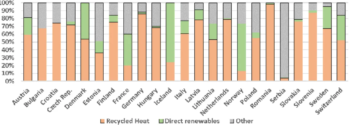
Figure 2.2 illustrates the energy supply composition for generated district heating in Europe [12]. The results differ from country to country, but in the majority of them the heat generation is essentially based on recycled heat. This parcel includes the surplus heat from electricity production (CHP), waste-to-energy plants and industrial processes. Additionally, approximately two-thirds of the waste-to-energy delivered by heat pumps, is also considered as recycled heat. The remaining part, is either based on the direct use of renewable energy sources and installations others than CHP, or in fossil fuel boilers and the other one-third of the heat originating from heat pumps.
In the larger systems, more than one source or technology can be used. In this case, a priority regime has to be established in order to guarantee that the system operation is as optimized as possible [16]. As such, the cheaper technologies are generally used during base load periods, whereas other more expensive are most commonly available as stand-by and peak load providers only.
Figure 2.2 – Energy supply composition for district heat generated among European countries in 2015. [12] In light of its flexibility, one can find a range of heat generation technologies associated to district energy systems. This topic is relatively well-documented, and various up-to-date public reports are available [17], providing extensive information in what regards technical and economic aspects. For this reason, this chapter focuses mainly on features within the scope of the project.
The table below list the main district heating technology options, along with its fuel source. Table 2.1 - Principal district heating technologies and its respective fuel source. [8] Technical solution Fuel source
Combined heat and
power (CHP) Gas, biomass, coal, biogas, waste
Heat Pump A heat source (e.g. ambient air, water or waste heat) and electricity Solar thermal Sun
Geothermal Heat from water underground Boiler Gas, biomass, oil products, electricity
Waste-to-energy plant Municipal solid waste and other combustible wastes
Waste heat recovery Waste heat from an industrial process or low-grade heat from sewage
Combined heat and power plants (CHP) are specific combustion units, capable of supplying both heat and electricity simultaneously. The heat is generated as a by-product of electricity production, which would otherwise be rejected or wasted. By recovering it, this technology is able not only to operate with higher efficiencies than conventional power plants, [13] but also to supply heat directly to consumers. In what concerns its priority regime, it is used to provide the baseload generation and, in order to achieve improved results [18], it is typically combined with thermal energy storage technologies. CHP is the most common solution implemented to supply areas with concentrated heat demand, and in fact, is responsible for almost half of the district heating production in Europe [12].
It is possible to operate a CHP plant with different levels of electricity and heat outputs by varying the ratio of produced power to heat, within a technical limited feasibility range [13]. Therefore, it can be operated to meet a specific heat demand or to follow electricity prices. In other words, it is possible to maximize the production of either heat or electricity, according to what is most advantageous at any
time. For instance, coupled with storage, the operator can take advantage of low electricity demand during night periods, to maximize heat production and store the surplus for later use.
Heat pumps (HP) are electrical units that, if coupled with thermal energy storage, are capable of performing similar operations. In fact, the retrofit of heat pumps with water storage to allow for their effective use in demand management services, is one key recommendation from IEA [6].
As expressed in table 2.1, heat pumps require a heat source in order to produce heat or cold, at adequate temperature levels. The thermal source is generally low temperature heat from the ambient air, water, ground or waste heat. This low-grade energy is converted to high-grade by putting in a required amount of compressor work, through electrical energy. The operating principle of this equipment will be later discussed in more detail, nonetheless, its main components are the electrically driven compressor, the condenser, the expansion valve and the evaporator.
The efficiency of a heat pump is determined by the Coefficient of Performance (COP). This parameter indicates the ratio of produced to used energy, and it mainly depends on factors such as, the temperatures of heat sink and heat source, the efficiency of its compressor, and the type of its working medium [19]. Above all, the temperature of the heat source and heat sink are very important factors for the COP value. To be specific, lowering the temperature difference between the heat source and heat sink, results in higher COPs, as indicated by equation 2.1.
𝐶𝑂𝑃 = 𝜂𝐶 ( 𝑇𝑠𝑖𝑛
𝑇𝑠𝑖𝑛−𝑇𝑠𝑜𝑟) (2.1)
Where, Tsin and Tsor are the heat sink and heat source temperatures respectively, and ηC is the relation
between the HP’s efficiency under real conditions and the theoretical maximum reachable (Carnot Cycle) [19].
A low temperature heating system and high temperature heat source is then beneficial. In fact, for every degree reduction in the heat sink temperature (Tsin), the COP improves 1-2 % [19]. And in turn, for every
degree enhancement in the heat source temperature (Tsor), the COP improves by 2-4% [19]. This makes
heat pumps attractive to be combined with technologies, such as waste heat recovery, geothermal, solar thermal and thermal energy storage in low to medium temperature applications [20].
Figure 2.2 - COP of water-to-water heat pumps according to the heating capacity range. The numbers above red bars represent number of units reported. [21]
This technology can deliver more useful energy than the required energy to operate it, which means that its efficiency can be higher than 1. IEA Annex 48 – subtask 1 [21], provides statistical performance data regarding an universe of heat pumps. It refers that, the average COP of an air-to-air heat pump can be up to 4, however, water-to-water heat pumps can reach even higher efficiencies. In addition, as it can be seen in figure 2.2, large capacity heat pumps typically present higher COP values.
Another important factor when characterizing the performance of a heat pump is how it behaves in partial load conditions. This aspect has to be considered, otherwise, the overall efficiency of the system may be affected. The available data on this topic proves that a proper sizing of heat pumps has great importance, in particular for water-to-water systems [21]. The next figure demonstrates the relation between the partial load factor (PLF) and the partial load ratio (PLR), for a water-to-water heat pump. It shows that if the HP is not sized properly, its efficiency can drop substantially in the milder seasons. However, the loss of efficiency associated to partial load running can be avoided by having thermal energy storage, which acts like a thermal buffer.
Figure 2.3 - Partial load factor vs. partial load ratio for water-to-water HP. [21]
To sum up, heat pumps are efficient technology for supplying both heating and cooling demands, particularly if coupled with thermal storage. Nonetheless, any technical solution mentioned on table 2, can be applied, according to which one is more adequate to each location.
As told already, solar thermal energy is commonly integrated with DH. Different solar thermal technologies exist [22]; however, it basically consists on using solar collectors to produce steam or hot water. In what regards its deployment, it can be implemented as a large centralized solution or as a distributed technology, providing only a minor contribution to the total heating load in a particular location of the grid. In addition, this system may also produce heat source for heat pumps, as described by these authors [20] [23].
Large-scale solar heating has a significant number of projects implemented [24]–[26]. The most relevant is the Solarthermie-2000 [27], and it consists on a German program, in which pilot and demonstration projects have been realized. The project was developed in order to support implementation of solar and seasonal thermal storage concepts.
Another renewable source of thermal energy is the ground itself. Geothermal technologies essentially make use of the more constant ground temperatures, at higher depths. This immunity to seasonal variations, make geothermal also optimal to be combined with reversible heat pumps [28]. During the heating season, the deep soil is warmer than outside air, and is used as heat source. Then again, in Summer is colder, and it serves as low grade cooling energy.
Due to its characteristics, geothermal technologies are cheap, operational stable and typically have a long lifetime. For these reasons, and given its immunity to seasonal variations, geothermal is typically used as base load provider [8]. This technology is considered to be underdeveloped, and an ongoing project is being carried out by the European Commission, in order to support further expansion [29]. Finally, to illustrate the potential of residual and waste energy, the next figure shows the existing district heat network connected in Amsterdam, and sources of unused heat [8]. The red lines represent the distribution grid. The yellow squares denote the consumer sites, and the orange circles are suppliers of heat. The map also shows possible future residual or waste heat sources from: hospitals (green circles), data centers (blues circles) and offices (purple circles).
Figure 2.4 – Existing district network in Amsterdam, and sources of unused heat. [8]
On balance, the already existing sources of unused energy are many, and as a result, one can only expect the number of future district energy connections to increase.
2.1.2. Cooling systems
Despite the existence of successfully implemented projects [8], [30], district cooling (DC) is not as commonly applied as district heating (DH). In fact, during last years, the expansion of DC in Europe is barely insignificant [30], keeping a constant supply of around 1% of the total cooling market.
On the contrary, global cooling demand is progressively becoming more relevant, as for example, the energy consumption related to space cooling increased [8] more than 60% during the past two decades. In this context, one can expect the number of operating DC systems to increase, as they provide an alternative way to improve cooling supply in terms of environmental impact and efficiency.
Similar to DH, district cooling systems produce and distribute chilled water, or brine, to a group of buildings. The water is carried by a piping network to the different locations, and it provides cooling by absorbing excess heat. The respective heated medium usually returns to the cooling plant, where is cooled again. Nonetheless, depending on the return temperature, this low-grade energy may also be stored on a long-term thermal storage unit, in order to be used on the next season as low-grade heat.
Each district system is unique and based on local conditions. For this reason, depending on local resource availability and energy prices, district cooling can use a number of technologies (table 2.2).
Table 2.2 - Main district cooling technologies and its respective fuel source [8]. Technical solution Fuel source
Electrical chillers Electricity, cold air or water.
Absorption chiller Surplus heat from waste incineration, industrial processes or renewable
source, and electricity for pumping.
Heat Pump Electricity, cold air or water.
Free Cooling Cold water from lakes, rivers or aquifers, and electricity for pumping.
An electrical chiller, or compression chiller is a cooling solution, normally air or water-cooled from natural sources. The main components of this chiller are the evaporator, the electrically driven compressor and the condenser. The excess heat is absorbed by the refrigerant, that evaporates and is then compressed by an electrical compressor to pass through the condenser, in which the refrigerant releases the heat. This process is also used by heat pumps to produce cold.
The electricity demand increase in many European nations over the last decades is, among other reasons related to the operation of electrical refrigeration equipment, particularly in the Summer peaks [31]. In addition, cooling is becoming more relevant as a factor of thermal comfort in the residential sector and is already essential to the services, which constantly require cooling to keep indoor temperature levels, or to other refrigeration processes [32].
Instead of electricity, absorption chillers use heat as primary energy. The cooling process is quite complicated; however, cooling is essentially generated by water being vaporized at low pressure [30]. This technical solution can be found in cities having access to waste energy from incineration or other industrial processes. Moreover, if coupled with a CHP unit this technology allows to centrally produce electricity, heat and cold (trigeneration plant). The absorption cycle is particularly interesting during Summer. During this period, the demand for heat in the district is low, and these facilities allow to increase the production of cold water, with higher efficiencies, by using the available excess heat in the system [31].
In the context of addressing the electricity demand increase related to cooling, free/natural cooling systems may be important technical solutions. It essentially consists on utilizing locally available natural cold-water reservoirs, such as lakes, aquifers, rivers or the sea, as long as their temperatures are low enough. Therefore, using air as natural cooling medium, limits the usability to northern latitudes, where it is cold outdoors for the main part of the year.
The amount of natural cooling that can be produced mostly depends on the water temperature variation during the year, and the district cooling supply and return temperatures. Furthermore, even if the main idea of DE is to utilize unused energy, sometimes in larger districts this is not enough, and some kind of peak production unit is also needed. In this case, depending on what is most advantageous, a compression chiller, heat pump or absorption chiller is often installed, in order to produce a sufficient DC supply temperature [30].
In short, when available, free cooling consists of a very simple, cost efficient and environmental friendly energy solution. Moreover, although other district cooling technologies run on electricity, their power consumption is in most cases lower than in distributed solutions. Therefore, DC is definitely capable of reducing the cooling related electricity demand, particularly in Summer peaks.
2.2. Heat and Cold Distribution
The second major component of district energy is the insulated piping network that carries the water or steam. This infrastructure consists of a two-circuit system – flow and return pipes. The flow, transports the water from the source to the consumers, and the return is responsible for taking the water back to the source. In addition, the supply of heat is independent from the supply of cold, which means that, there is a piping network for heating and another for cooling. Moreover, the piping system is often the most expensive part of the district energy [9].
The type of distribution grid is mainly determined by site conditions such as, the layout of roads or the arrangement of the houses to be connected. However, the network size and the number of energy sources, are also decisive factors [33]. Essentially, there are three grid configurations, as showed in the next figure.
Figure 2.5 – Types of district energy networks: (a) Radial systems; (b) Ring networks; (c) Meshed networks. [33] Due to its simplicity, radial systems are mostly used for smaller districts. The short piping paths and smaller diameter, result in lower construction costs and heat losses. The disadvantage of this configuration however, is that future extensions are only possible to a small extent.
On the other hand, ring networks are often used to supply larger areas with one or more thermal sources. With this configuration, not only different energy sources can be integrated, but it also results in higher supply security, as most consumers can be reached via two piping paths. This makes future extension or adding new equipment easier.
The last arrangement consists on meshed networks, which are ring grids nested inside each other. These offer optimum supply security and better expansion opportunities. Because of the related high investment costs, this configuration is mostly implemented in large distribution networks.
A number of aspects have to be taken into consideration when designing a distribution network. According to the district heating and cooling connection handbook [16] the dimensioning of the distribution grid is mainly ruled by three factors:
- The temperature difference between supply and return; - The maximum mass flow rate (velocity and pipe diameter);
- The required differential pressure to overcome the flow resistance, and reach the most remote consumers.
The thermal capacity of the district is determined by both rate of water flow and temperature difference between supply and return. A large temperature differential means that less water has to be dispatched, in order to carry the same energy; in other words, the mass flow rate can be lower. This allows to use smaller pipes, leading to a reduction in the heat losses/gains, pumping power and initial capital investments.
The system temperature difference (supply/return) is typically limited to 8-11ºC for cooling, and 15-30ºC for heating. The maximum allowable flow velocities are governed by pressure drop constrains and other hydraulic disturbances, but in general, velocities higher than 2.5 – 3 m/s should be avoided [16]. In what concerns the water flow, it can be either constant or variable [9]. Constant flow is typically applied only on smaller systems, where simplicity of design and operation are important, or where distribution pumping costs are low. In addition, constant flow distribution is also applied to in-buildings circuits, with separated pumps. Variable flow is a more efficient solution. By using meters to track the load and variable speed water pumps, a high temperature difference (supply/return) can be maintained, since the pump can reduce flow and pressure, during partial load time.
When establishing design flows for thermal distribution systems, the diversity of the consumer demands should be considered. In particular, when in time do the maximum demands of the various consumers occur, and how the consumption is geographically distributed in the district, are two questions to address. By doing this, the energy supply and main distribution piping may be sized for a maximum thermal load.
Regarding thermal losses, it mainly depends on three parameters [16]: - Amount of pipe insulation;
- Pipe dimensions (diameter and length); - Supply and return temperatures;
The amount of pipe insulation generally results from a balance between capital investment and operation performance, as better insulation means more expenses. In short, reduced diameter and length, low temperatures and high insulation values are beneficial.
Many reports address thermal energy distribution in district systems. Since the decreased thermal demand from low-energy buildings affects the cost-effectiveness of traditional districts, authors have been focusing on optimized design concepts, mainly based on lower distribution temperatures and new equipment. Dalla Rosa et al. [34] showed the advantage of low supply and return temperatures and their effect on energy efficiency. The total primary energy use was 14.3% lower when compared to a standard network. Moreover, the thermal distribution losses were halved. This study also concludes that a district heating design optimized for low-temperature operation, is superior to a design optimized for low-flow operation.
Another relevant report addressing low temperature distribution was developed in the context of a Danish Energy Agency R&D Programme [35]. It defines low temperature distribution as a system in which, all components can operate in the range between 40-65ºC for supply, and 25-45 ºC for return flow, while meeting consumer demands for indoor thermal comfort. Moreover, this report states the benefits of low temperature heating, as well as how this concept can be applied in new or existing districts. A number of case studies is also presented. Finally, methods for determining distribution thermal losses [9], [36], as well as, friction pressure losses [37], [38] are also available in literature.
2.3. Heat and Cold Consumption
The interface between the district energy and the building systems is commonly referred to as the consumer substation. It consists on a number of control valves, measurement instruments and heat exchangers [16]. The heat exchanger is responsible for transferring heat from the distribution piping, to
the consumer system or vice versa, creating a hydraulic separation. Nonetheless, a direct connection is also possible in which the district water is distributed, within the building, directly to terminal equipment such as a fan coil unit. Controls are another major component of the substation. An adequate control strategy can reduce energy costs and optimize conditions for the equipment, while maintaining comfortable temperatures in the building [16].
The consumer’s behavior largely influences the energy load [34]. In addition, the energy demand also depends on building constructive elements, such as, walls, windows, size, etc. For designing and operation purposes, the building’s global thermal demand is a central calculation. When existing, this parameter should be established based on historical energy usage. Otherwise, the expected building thermal demand may also be predicted, within a range of error.
In order to determine the thermal demand of a building, a dynamic building model is generally used. This model can be implemented in an adequate software and based on a number of inputs, it returns the expected space heating or cooling demand, along with other useful data. Different standard models exist, but it is very popular to use an equivalent circuit model, such as the ones, described in the German standard VDI 6007-1 of 2007 or ISO 13790 [39], [40]. Because of the increased complexity and number of objects, when modelling at district level, the idea is to use the simplest method possible, which requires lesser computational resources, while keeping the results in an acceptable range of error for each application.
Another very important calculation is the building’s peak load. The district has to be designed to provide enough capacity to deliver each building’s peak thermal needs, during peak periods. If the system is under designed, the customers will be uncomfortable. In turn, if the system is overdesigned, the costs to deliver energy increase, which may affect the economics of the entire system.
In addition to occupant’s behavior, internal gains and constructive elements, weather is also a significant factor when determining the above referred parameters. Heating and Cooling demands and peaks depend on conditions like the outdoor temperatures and the durability of these, solar radiation, wind direction or humidity. In fact, humidity is particularly relevant when calculating cooling demands [30].
The cooling demand is basically the amount of heat to be removed from a building, to maintain it at indoor design temperature. As the warmer air to be air-conditioned has greater moisture content than chilled air, a significant amount of cooling load in buildings is attributed to dehumidifying air in the form of latent heat [41]. Figure 2.6 shows an example of a daily profile of latent and sensible cooling loads in an apartment building in Hong Kong, where it can be seen that latent heat is comparable to sensible load during some periods of the day.
Moisture is mainly introduced into the building through people, equipment and air infiltration [41]. Therefore, a substantial share of the cooling demand in a building is created by heat from the usage inside the building, and not due to the hot weather outside. In fact, contrary to general perception, the location of existing district cooling systems illustrates that the difference in climatic conditions between the countries in Europe does not play such an important role with regard to the specific cooling demand, as DC is actually more frequently established in countries with colder climate, than in warmer climate ones [30].
2.4. Final remarks
Latest generation DE is an energy efficient technology capable of reducing primary energy use and greenhouse gas emissions. This system is very flexible and is designed taking into consideration local resources and potential sources of already existing unused energy. It works like a technology hub, allowing to combine different equipment for greater performance. Moreover, a number of heating and cooling technical solutions are available and can be used, according to which one is more advantageous at each location.
When analyzing a district energy, a number of parameters have to be considered. For instance, the global thermal demand and respective peaks, supply and return temperatures, mass flow rates, pressure requirements or equipment efficiency are important variables.
Finally, as thermal demand density decreases in areas of low-demand buildings, researchers propose new distribution methods, based on low temperature distribution. This approach can reduce primary energy use and thermal losses. In addition, with low temperature heating, heat pumps are more attractive, since its main limitation is that it can only elevate water temperature to a given extent. With this system, heat pumps may efficiently supply both heating and cooling demands, sometimes even without the need for peak units, especially if combined with any low-grade energy source, immune to seasonal variability.
Chapter 3 - Energy Storage
Energy Storage (ES) can be defined as any installation or method, at any place of the power or district system, in which it is possible to store energy, keep it stored, and later retrieve it when necessary [42]. The modern concepts of ES emerged essentially from the energy crisis in the 1970s. More recently, the pursuit for solutions to achieve energy system decarbonization has been attracting increased awareness to its advantages.
First of all, storing energy allows to dissociate energy supply and demand, thus increasing the overall system reliability. This can be particular important since the most limiting aspect of renewable energy production is, its intermittent behavior [42], [43]. In fact, Daim et al. [44] refers that in order for renewable energy resources to become completely reliable as primary sources, energy storage is essential.
Moreover, decoupling supply and demand, also result in increased effective generation capacity and energy security. In other words, the demand is rarely constant over time, and the excess generation during low-demand periods can be used to charge a storage unit, therefore increasing the overall capacity for high demand periods. This also implies that cheap energy during off-peak periods is being stored, and can be later recovered. Regarding the production equipment, this process results in a more flattened energy output, which allows smaller capacity to be installed, with lower partial load operation and better efficiency [43].
Another benefit is that energy storage can be utilized to combine different forms of energy, thus conferring greater flexibility. For instance, in recent decades, TES systems have demonstrated the capability to shift electrical heating and cooling loads, from peak to off-peak hours [45]. This process has many advantages both for customers and utilities. Customers have more efficient systems and save money, if they take advantage of different electricity prices, and the same applies to utilities that can spread the demand over more time.
Each storage technology has unique characteristics and is different in terms of its appropriate application and scale. Due to this versatility, the appropriateness of any storage system is generally evaluated, based on certain parameters [42]. Some of these are listed in the following table, along with a brief description.
Table 3.1 - Criteria for selecting energy storage technologies. [44] Parameter Description
Power density Rated output power divided by the volume of the whole storage system. Energy density Stored energy divided by the volume of the whole storage system.
Self-discharge Portion of energy that is dissipated over a given amount of non-use time. Response time Speed at which the energy is released or absorbed.
Capacity The available quantity of energy in the storage system, when charged. Efficiency Performance of the process of storing and retrieving energy.
Lifetime The energy storage cost depends on investment costs and projected lifetime. Others Monitoring & control equipment, economics and other operating constrains.
In general, energy storage systems are classified as either thermal or electrical [43]. This project focuses on thermal energy storage, however, a short overview on electrical energy storage is also provided on the next sub-chapter.
3.1 Electrical Energy Storage
Electrical energy storage (EES) embraces a number of technologies, which directly or indirectly, store energy through an electric input and output. As electricity is the most versatile and preferred form of energy for many applications, the importance of further developing this topic is obvious. In fact, it can be crucial to enable the widespread [44] of large-solar or wind-based power generation [46], as well as, electric vehicles, for example.
Electricity can be stored with different methods: [42] Mechanically by pumping water to higher reservoirs, compressing air or increasing the rotational speed of electromagnetic flywheels; chemically by using components such as batteries, flow batteries or fuel cells; and finally, electrically by modifying electric or magnetic fields in capacitors or super conducting magnets. The main EES technologies are grouped by storage method in the next figure.
Figure 3.1 - Principal electrical energy storage technologies [44]
Electrical energy storage systems are broadly described in literature [48]–[50]. Among other authors, T. Kousksou et. al. [42] released an article providing a comprehensive overview on EES. The study focuses on state of the art systems and installations, as well as, the main characteristics of energy storage. The following table summarizes a small piece of information present in this report. As mentioned before, the suitability of each technology for a specific application is assessed through the analysis of technical characteristics.
Table 3.2 - Comparison of some technical characteristics of electrical energy storage systems [42]. Efficiency [%] Capacity [MW] Energy density [Wh/kg] Response time Lifetime [years] Pumped hydro 75-85 100-5000 0.5-1.5 Fast (ms) 40-60
Compressed air 50-90 3-400 30-60 Fast 20-60
Flywheel 90-95 0.25 10-30 Very fast (< ms) ~15
Battery 60-90 0-40 30-240 Fast 5-20
Flow battery 75-85 0-15 10-50 Very fast 5-15
HES (fuel cells) 20-50 0-50 800-10000 Rapid (< 1 s) 5-15
Capacitors 60-65 0.05 0.05-5 Very fast ~5
Supercapacitors 90-95 2.5-15 2.5-15 Very fast 20+
SMES 95-98 0-10 0.5-5 Very fast 20+
Electric energy storage systems
Mechanical Pumped hydro storage (PHS) Compressed air energy storage (CAES) Flywheel Energy storage (FES) Electrochemical Battery energy storage (BES) Flow battery energy storage (FBES) Chemical Hydrogen based energy storage (HES) Electrical Capacitor and supercapacitor energy storage Superconducting magnetic energy storage (SMES)
3.2 Thermal Energy Storage
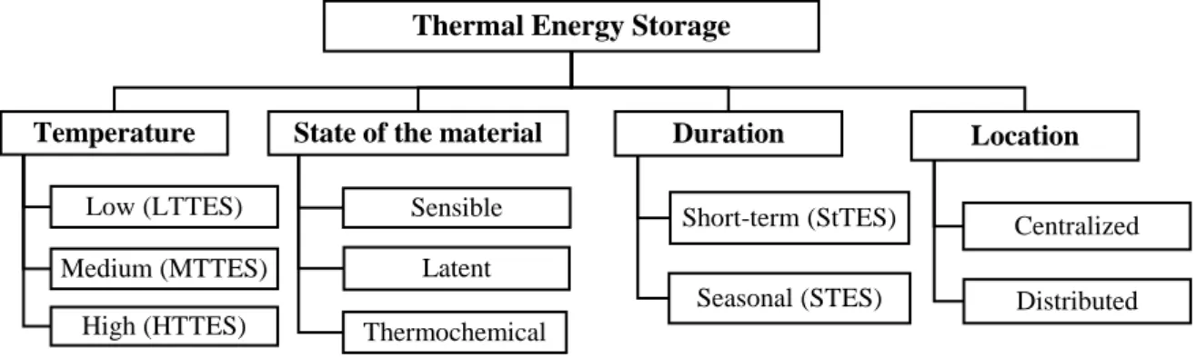
The concept of thermal energy storage is to store energy by cooling, heating, melting or solidifying a material. Various TES categories exist, based on different criteria, such as, storage temperature, duration, etc. [43]. The next figure lists the criteria within the scope of this project, along with the respective categories.
Figure 3.2 - Thermal energy storage categories, according to criteria relevant to this project.
In what concerns the location in the district, TES can either be centralized or decentralized. The first is generally a large capacity unit, connected to all or the majority of the components in the system. The decentralized or distributed approach is when storage is applied in a smaller scale, associated to a particular building or specific part of the network. Both concepts are analyzed in this project. In addition, regarding the temperature level, this project focuses on low temperature thermal energy storage (LTTES), therefore medium and high temperature TES will not be addressed. Thermal energy storage can also be classified according to the state of the storage material. The next paragraphs provide an overview on sensible, latent and thermochemical TES.
In sensible storage systems, energy is stored by changing the temperature of a storage medium. The amount of energy stored in the medium is given by [43]:
Q = m ∙ 𝑐𝑝∙ (𝑇𝑓 − 𝑇𝑖) [J] (3.1)
Where, m is the mass of the storage medium [kg], cp is the medium’s specific heat capacity
[J·Kg-1·K-1], T
i is the medium initial temperature [ºC] and Tf is the final temperature [ºC]. For some
systems, it is also useful to describe mass as function of its volume (V) [m3] and density (ρ) [kg·m-3], as
follows:
m = V ∙ ρ [kg] (3.2)
In addition, the maximum storage capacity may also be determined using equation 3.1, if the final and initial temperatures are replaced by the fully charged and fully discharged temperatures, respectively [19].
Different authors [19], [50] report that the storage medium is essentially determined based on the required temperature level, storage duration, and rate at which energy must be released or extracted. For this reason, the choice of sensible storage materials is very dependent on the following properties:
Thermal Energy Storage
Temperature
Low (LTTES) Medium (MTTES)
High (HTTES)
State of the material
Sensible Latent Thermochemical Duration Short-term (StTES) Seasonal (STES) Location Centralized Distributed
- Volumetric thermal capacity (ρ·cp), which quantifies the ability of a given volume of material
to store sensible thermal energy; - Thermal Diffusivity (λ·ρ-1·c
p-1), which measures the thermal inertia of a material. A bigger value
means that the material will rapidly react to a temperature change.
In addition to high volumetric thermal capacity and low thermal diffusivity values, stability when charging and discharging and low material costs, are also important characteristics of sensible storage mediums. In this context, water, concrete, rocks, gravel, sand or the ground itself are reliable, simple and low-cost materials for storing energy [50].
Among the above referred mediums, water is considered to be the most favorable material for sensible energy storage due to its high specific heat and high capacity rate, while being charged and discharged. Even so, all mediums have their own advantages and disadvantages [19]. Basically, the thermal capacity of liquids is higher than that for solids. In turn, solids can tolerate a higher range of temperatures since they will not freeze or boil, and these cannot leak from the container.
In short, sensible TES is a matured method, applied in different contexts, generally related to space heating and cooling or domestic hot water supply. The required temperatures for these applications range from 15 – 60 ºC, in low temperature systems. This makes water and other rock sort materials very attractive, as sensible storage mediums. Over the past years, a number of studies have been carried out focusing on sensible thermal storage. The major part of the efforts aimed to the resolution of specific issues (e.g. new water tank concepts) and new materials [50], [51].
Another method to store thermal energy is in latent form, using phase change materials (PCMs). This technology can offer higher energy density than sensible storage, however it stills in a yearly stage of development, especially in what concerns its implementation in district systems [52]. The energy is stored as heat of fusion when melting occurs, at a nearly constant temperature (see figure 3.3 – left). If the temperature decreases to the phase change temperature, the material changes back to solid phase, and releases the stored energy. The amount of energy stored in PCMs is given by [53]:
Q = m ∙ [𝑐𝑝−𝑠𝑜𝑙𝑖𝑑(𝑇𝑚− 𝑇𝑖) + 𝑎𝑚∙ ∆ℎ + 𝑐𝑝−𝑙𝑖𝑞𝑢𝑖𝑑(𝑇𝑓− 𝑇𝑚)] [J] (3.3)
Where Ti, Tm, Tf are the initial, melting and final temperatures [ºC], respectively, cp is the specific heat
capacity [J·kg-1·K-1], a
m is the melted fraction of the material, and Δh is the enthalpy change at the phase
change temperature [J·kg-1]. Materials used for storing energy in latent form (PCMs), should have a
high heat of fusion and a phase change temperature within the operating range of the thermal system. The right side of figure 3.3, shows various PCMs and their phase change temperatures [54].
Figure 3.3 – Left - Temperature and stored heat for a solid-liquid phase change, compared with sensible heat [53]; Right - Classes of materials that used as PCMs and their typical range of phase change temperatures and melting enthalpy [54].
Based on the literature collected, appears to be potential for the integration of latent thermal storage in district networks. Nonetheless, at this scale this technology is very undeveloped, as most of present work is based on small scale prototypes or in computational models [52]. Examples of this line of work are the five PCM-related projects resulting from IEA-SHC task 32 [55]. According to the task participants, screening for better PCMs with higher heats of fusion and heat transfer rates, should be addressed in the future. By contrast, ice storage for cooling purposes is already a relatively mature latent technology, currently in commercialization phase [43].
Finally, a more recent method to store thermal energy is thermochemical energy storage. It is based on reversible chemical reactions between two substances, which are energy demanding in one direction and energy yielding in the reversed way. No reaction occurs as long as the two materials are stored separately, allowing to store thermal energy until the two substances are mixed together [53].
This method is seen as the most promising alternative to store thermal energy. With this technology, it is possible to store energy at ambient temperature, for the desired duration, with negligible heat losses, making these systems suitable for long-term applications. In addition, it has the highest energy density when compared to sensible and latent solutions [52].
Current work focuses on developing new stable, non-polluting and cost-effective materials [53]. However, this technology is still on yearly stages of development. Prototypes and demonstration projects have already been developed, mainly related to long-term thermal storage. Examples of these are the watergy and SWEAT (Salt water energy accumulation and transformation) projects [52].
The case study considered in this project focus on sensible thermal storage. This method is used for both short-term and long-term applications. The following sub-sections address this topic.
3.2.1. Short-term thermal storage
A very common technical solution for short term sensible TES is the water tank, often operating in daily storage cycles. Tanks are ideal for water storage since they are cheap and easy to produce. The major challenge with water tanks however, is the space they occupy. In fact, the available space plays a decisive role when sizing the storage unit, particularly in domestic applications [17]. By increasing the temperature of one kilogram of water 1ºC, its energy content increases approximately 4.18 kJ. Similarly, in order to cool the same amount by 1 degree, an equal quantity of energy is released/absorbed. To illustrate, for a temperature difference of 20ºC, the storage capacity is approximately 84 kJ/kg. This means that, to deliver a heat output of 1 kW a full week, a water tank of about 7200 liters is needed. In addition to space availability, the optimum size of the storage also depends on other factors, such as, weather, building heat loads, equipment efficiencies, temperature levels, costs, and most importantly, the application for which is designed [56]. Short-term TES can be used to optimize energy systems in different ways and scales.
To begin with, it may be utilized to meet fast fluctuations on the thermal demand, which is particularly useful when the heating or cooling equipment has slow response time, as it is the case with some boilers, for instance. Moreover, thermal storage is often combined with solar thermal technologies. In this context, it can help to neutralize the instability of the weather, as for example, the appearance of clouds [17].

![Figure 2.3 - Partial load factor vs. partial load ratio for water-to-water HP. [21]](https://thumb-eu.123doks.com/thumbv2/123dok_br/18191889.875444/19.892.232.662.419.647/figure-partial-load-factor-partial-ratio-water-water.webp)
![Figure 2.4 – Existing district network in Amsterdam, and sources of unused heat. [8]](https://thumb-eu.123doks.com/thumbv2/123dok_br/18191889.875444/20.892.163.731.328.666/figure-existing-district-network-amsterdam-sources-unused-heat.webp)
![Table 2.2 - Main district cooling technologies and its respective fuel source [8].](https://thumb-eu.123doks.com/thumbv2/123dok_br/18191889.875444/21.892.113.759.193.349/table-main-district-cooling-technologies-respective-fuel-source.webp)

![Table 3.2 - Comparison of some technical characteristics of electrical energy storage systems [42]](https://thumb-eu.123doks.com/thumbv2/123dok_br/18191889.875444/28.892.116.762.890.1140/table-comparison-technical-characteristics-electrical-energy-storage-systems.webp)
![Figure 3.3 – Left - Temperature and stored heat for a solid-liquid phase change, compared with sensible heat [53]; Right - Classes of materials that used as PCMs and their typical range of phase change temperatures and melting enthalpy [54]](https://thumb-eu.123doks.com/thumbv2/123dok_br/18191889.875444/30.892.165.732.899.1100/figure-temperature-compared-sensible-classes-materials-temperatures-enthalpy.webp)
![Figure 3.4 - Breakdown of electricity consumption among residential end-use equipment in EU-15 (black slices represent electricity consumption for heating and cooling that can be managed by TES) [45]](https://thumb-eu.123doks.com/thumbv2/123dok_br/18191889.875444/32.892.231.664.586.845/breakdown-electricity-consumption-residential-equipment-represent-electricity-consumption.webp)