Dynamic Replication: The Core of a Truly Non-Intrusive SRAM-based FPGA
Structural Concurrent Test Methodology
Manuel G. Gericota, Gustavo R. Alves
Department of Electrical Engineering — ISEP
Rua Dr. António Bernardino de Almeida
4200-072 Porto - PORTUGAL
{mgg, galves}@dee.isep.ipp.pt
Miguel L. Silva, José M. Ferreira
Dep. of Computers and Electrical Engineering — FEUP
Rua Dr. Roberto Frias
4200-465 Porto - PORTUGAL
{mlms, jmf}@fe.up.pt
Abstract
♦
♦
♦
♦
The increasing use of reconfigurable computing platforms, employing SRAM-based FPGAs, opens exciting new possibilities since they enable the reutilization of the same hardware resources to implement speed-critical computational tasks, without interrupting system operation.
Nevertheless, larger dies and the use of smaller submicron scales in the manufacturing of this new kind of FPGAs increase the probability of lifetime operation failures, requiring new test / fault-tolerance methods capable of assuring the reliability of the system.
Structural concurrent test procedures become particularly important in this context, since it is now possible to replicate and release for test internal FPGA resources, concurrently with — but not affecting — system operation. A new dynamic replication process of active Configurable Logic Blocks (CLBs) is presented in this paper, which enables the implementation of a truly non-intrusive structural concurrent test approach. The experimental results presented prove the effectiveness of this solution.
1. Introduction
The advent of a new kind of SRAM-based FPGAs (Field Programmable Gate Arrays) capable of
♦This work is supported by the Portuguese Foundation for Science and
Technology (FCT), under contract POCTI/33842/ESE/2000
implementing fast run-time partial reconfiguration (e. g. the Virtex family from Xilinx), enabling the dynamic customization of hardware functions to a particular system or application concurrently with system operation, considerably reinforced the advantages of the use of complex configurable logic devices in reconfigurable computing platforms.
Unfortunately, the smaller submicron scales used in the manufacturing of these devices increase the threat of electromigration, due to higher electronic current density in metal traces. Also, the corresponding lower threshold voltages make them more susceptible to gamma particle radiation. Radiation interference is much more likely with larger dies, increasing the probability of failure [1-2]. After large periods of operation, certain defects, namely those related to small manufacturing imperfections not detected by production testing, become exposed, emerging as either stuck-at faults or transient faults [3].
A higher FPGA reliability level can therefore only be achieved through the continuous test of all its blocks throughout system lifetime, and by the introduction of fault tolerance features. In [4] the authors proposed a new methodology to dynamically rotate and free-for-test the CLBs in an FPGA, without disturbing system operation, and presented some effective results concerning the adopted strategy to implement the rotation scheme. Equally important in this methodology is the replication of active CLBs, i.e. those CLBs that are part of a functional block actually being used by the system. In order to free the CLBs to be tested, their function must be replicated in CLBs previously tested, in a way that must be completely transparent for the system.
In this paper a new replication strategy is proposed, which enables the complete implementation of a truly non-intrusive structural test of the FPGA CLBs for permanent failures that may eventually emerge during system lifetime. The proposed strategy does not require the usage of any FPGA I/O pins, since it reuses the IEEE 1149.1 infrastructure [5] to access the configuration resources and to apply / capture test vectors. While testing the various CLBs, our procedure also tests a significant fraction of all available routing resources.
This paper is organized as follows: recently proposed approaches to the test of SRAM-based FPGAs are first reviewed, followed by a general description of the structural concurrent test solution envisaged for the FPGA CLBs. The rotation strategy employed to free the CLBs and the adopted test approach are briefly reviewed. The following section details the replication mechanism and presents experimental results. In the end, some directions for further research are introduced.
2. Background
Different off-line test methodologies of SRAM-based FPGAs have been proposed in recent publications, employing a diversity of Built-In Self-Test (BIST) strategies or external test procedures. An FPGA test approach based on BIST techniques, presented in [6-7], exploits the reprogrammability of FPGAs in order to set up the BIST logic, which exists only during off-line testing. Testability is achieved without any area overhead or performance penalty, since the BIST logic is eliminated when the circuit is reconfigured for normal operation. A different BIST architecture, based on the same strategy, was also proposed to enable fault diagnosis [8-10].
An off-line test based on a non-BIST approach, targeted to test the FPGA CLBs, is presented in [11-12]. In order to achieve 100% fault coverage at CLB level, different test configurations are set up sequentially, with series of test vectors being applied to each of them through the FPGA I/O Blocks (IOBs).
Since fault-detection latency is much larger in off-line test strategies, these approaches are unsatisfactory in highly fault-sensitive, mission-critical applications, and as a consequence are restricted to manufacturing test.
In order to overcome these limitations, on-line test methods based on a scanning methodology were presented in [3, 13-15]. The basic concept underlying these methods consists of having only a relatively small portion of the chip being tested off-line (instead of the whole chip as in previous proposals), while the rest continues its normal operation. If the functionality of a column of FPGA CLBs can be replicated on another portion of the device, then it can be taken off-line and tested for faults in a transparent
manner (i.e. without interrupting the system functionality). This fault scanning procedure then moves on to copy and test another column of CLBs, sweeping through the whole FPGA, systematically testing for faults. In this approach, known as Roving STARs, the whole system must be stopped in order to replicate the columns. Since reconfiguration is performed through the Boundary Scan (BS) infrastructure, reconfiguration time is long, and it seems likely that halting the system will disturb its operation. The new partial and dynamic reconfiguration features are not entirely exploited by this approach, possibly because dynamic replication of an entire column would cause too many disturbances to the system operation.
The concurrent test approach proposed in this paper reuses some of the previous concepts, but eliminates their drawbacks by using a much smaller unit of test – the CLB. The replication of each CLB is accomplished without halting the system, even if the CLB is active.
The use of the BS test infrastructure to access FPGA configuration memory, and to apply the test vectors and capture the responses in each CLB, brings the additional benefit of a reduced overhead at board level, since no other resources (than those of the FPGA itself) are used. Being application-independent, and oriented to test the FPGA structure, the proposed strategy guarantees FPGA reliability after many reconfigurations, thus helping to ensure the correct operation throughout the system lifetime.
3. The proposed FPGA concurrent test
solution
In the vast majority of reconfigurable hardware systems, multiple independent hardware blocks dynamically share the same FPGA device at the same time. Nevertheless, 100% usage of the FPGA resources is hardly ever achieved, so a few blocks will always be free. The DRAFT (Dynamically Rotate And Free for Test) method presented in [4] is based in a scanning technique where temporarily unused FPGA CLBs are structurally tested without disturbing system operation, taking advantage of the dynamic and partially reconfigurable features offered by new FPGAs.
Using a dynamic replication and rotation mechanism, CLBs currently being used by a given application can have their functionality dynamically replicated in one of the CLBs already tested. After transferring its functionality, the replicated CLB is free to be tested. Carrying out a rotation scheme that covers the whole FPGA, this solution guarantees that the whole FPGA can be tested, without disturbing the system operation, provided that at least one unused CLB is available in the
current implementation. The introduction of fault tolerance features will however require more than one unused CLB, since a pool of spare resources has to be continuously available to replace those eventually found defective. Unlike Built-In Self-Repair (BISR) techniques used in manufacturing, our solution is able to dynamically tolerate faults in the field. In this way, the system can still operate in the presence of faulty CLBs, and dependability is improved with reasonably low hardware redundancy and no extra cost.
4. Rotating and testing
The rotation strategy followed in order to free CLBs for test should have a minimum influence (preferably none) in the system operation, as well as a reduced overhead in terms of reconfiguration cost. This cost depends on the number of reconfiguration frames needed to replicate and free each CLB, since a great number of frames would imply a longer test time and larger memory resources. The impact of this process in the overall system operation is due to variations on circuit timing, because of routing adjustments. If the re-routing procedure originates a path delay higher than the previous maximum, the system’s maximum frequency of operation is reduced and the overall system performance degrades.
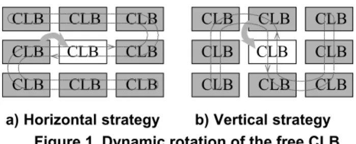
Three possibilities were considered for establishing the rotation rule of the free CLB, among the entire CLB array: random, horizontal and vertical rotation [4].
The random strategy was rejected for three main reasons:
- it generates longer paths (and hence increases path delays);
- it puts too much stress in the limited routing resources, by dispersing groups of CLBs assigned to a same function;
- it has unpredictable fault coverage latency, which is not acceptable.
The second strategy, horizontal rotation, is illustrated in figure 1-a). The free-for-test CLB (in white) would rotate along a horizontal path covering all CLBs in the array. The replication process would take place between neighboring CLBs, due to scarcity of routing resources and to higher path delays. The same rule applies as well to the vertical rotation strategy illustrated in figure 1-b), where the CLB under test rotates along a vertical path.
Simulations performed with the last two strategies, using Virtex Xilinx FPGAs, over a subset of 14 ITC’99 Benchmark Circuits from the Politécnico di Torino [16], have shown that the vertical rotation strategy achieves lower costs in terms of reconfiguration file sizes. The size obtained by the application of the horizontal strategy was around 20% higher than what was obtained by the
application of the vertical strategy to the same circuit implementations.
a) Horizontal strategy b) Vertical strategy
CLB
CLB
CLB
CLB
CLB
CLB
CLB
CLB
CLB
CLB
CLB
CLB
CLB
CLB
CLB
CLB
CLB
CLB
Figure 1. Dynamic rotation of the free CLB
The influence of both rotation strategies over the maximum frequency of operation was substantially different, mainly due to a pair of dedicated paths per CLB that propagate carry signals vertically to adjacent CLBs. When the rotation process breaks a dedicated carry path, due to the insertion of the free CLB, the propagation of this carry signal between the nearest adjacent CLBs (above and below) is re-established through generic routing resources, increasing the path delay. If the implemented circuit has one or more of these carry signals, the horizontal rotation would break all the carry nets, increasing path delays, but the vertical rotation would only break those in the top or bottom of the CLB columns. The vertical rotation strategy is therefore preferable, if we consider only the degradation in the maximum frequency of operation.
When no carry signals are used, two other factors must be considered: i) the number of signals with high fanout, and ii) the placement shape (rectangular, square, circular, etc.) and orientation (horizontal, vertical) of the circuits implemented inside the FPGA. In rectangular / horizontal implementations, and when many high fanout signals are present, the horizontal strategy becomes preferable, since the maximum frequency of operation is less degraded (this could be a more important factor than reconfiguration file size when dealing with high-speed applications).
The BS infrastructure is also reused to access the CLBs during the test process. In order to create the test model of the Virtex CLB structure, some restrictions had to be imposed:
- the carry logic would not be tested, because it is not possible to access the CLB carry input and output ports directly (only by passing through the vertically adjacent CLBs);
- the use of LUTs (Look-Up Tables) as Distributed RAM would not be initially considered.
Each VIRTEX CLB comprises two slices exactly equal. In total, the CLB test model has 13 inputs (test vectors are applied to both slices of each CLB simultaneously) and 12 outputs (six from each slice).
Test vectors are applied and responses captured through the BS infrastructure, with the outputs of the CLB
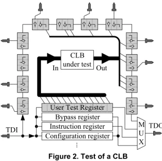
under test being routed to unused BS register cells associated to the IOBs. However, and since the application of test vectors through the BS register would affect the values present at each FPGA input, an alternative User Test Register must be used (the Virtex family enables the definition of two user registers controlled through the BS infrastructure), as shown in figure 2. This User Test Register comprises 13 cells, corresponding to the required number of CLB test configuration inputs. M U X Out Bypass register Instruction register Configuration register In TDO TDI ... CLB under test
User Test Register
Figure 2. Test of a CLB
The number of CLBs occupied by this register (seven), associated to the CLB needed to perform the rotation, are the only hardware overhead implied by our proposed test methodology. This accounts for 0,7% of the CLB resources in a Xilinx XCV200, a medium size complexity FPGA (array size = 28x42 CLBs). Since the outputs of each slice are captured independently, fault location can be resolved to a single slice.
As the implementation structure of the CLBs multiplexers and flip-flops was not known, we considered a hybrid fault model [11]. The analysis of the Virtex CLB test model structure led us to conclude that four test configurations were enough to exercise all possible CLB faults. Since reconfiguration through the BS infrastructure is slow, this small number of test steps is a good measure of our reduced test time.
The back-and-forth dynamic free-CLB rotation across the chip implies a variable test latency. The time to again reach a given CLB alternates between a maximum and a minimum value (according to the rotation direction), depending on the size of the device:
- the maximum fault detection latency is given by: ) ( 2 ) 2 ) #
((# rows columns reconf test
scanMAX = CLB × CLB − × ×t +t
τ
- the minimum fault detection latency is in turn given by: ) ( 2 reconf test scanmin = × t +t τ where:
treconf: time needed to complete a CLB replication
ttest: time needed to test a free CLB
The maximum fault latency obtained experimentally in essays performed with the XCV200, at a BS operation frequency of 30MHz, was 48 seconds.
After a complete back-and-forth dynamic free-CLB rotation, the initial routing is restored, and therefore no cumulative performance degradation results by continuously repeating this process.
In our approach, the configuration memory is considered fault free and will not be tested. However, the same test infrastructure could be used to perform a readback of the configuration data that was loaded into the FPGA, helping to detect faults in the configuration elements. With this aim, a readback and compare software application, capable of performing full readback configuration memory through the Standard BS test access port, was developed. The readback file is compared with the original configuration file, in search of differences indicating the existence of possible faults in the configuration memory.
5. A novel replication process
The rotation mechanism implies the replication of active CLBs. This task is not trivial due to two major issues: i) configuration memory organization, and ii) internal state information.
The configuration memory can be visualized as a rectangular array of bits, which are grouped into one-bit wide vertical frames extending from the top to the bottom of the array. One frame is the atomic unit of configuration — it is the smallest portion of the configuration memory that can be written to or read from. These frames are grouped together into larger units called columns. Each CLB column has a corresponding configuration column, with multiple frames, that mixes internal CLB configuration information, routing information and state information. The configuration process is a sequential mechanism that spans through some or the whole CLB configuration columns. When replicating an active CLB, its input and output signals (as well as those in its replica) may cross several columns before reaching its source or destination. Any reconfiguration action must therefore ensure that the signals from the replicated CLB are not broken before being totally re-established from its replica. Also important, to avoid output glitches, the functionality of the CLB replica must be perfectly stable before its outputs are connected to the system. A set of experiments
performed with a XCV200 demonstrated that the only possible solution is to divide the replication process in two phases, as illustrated in figure 3. In the first phase, the internal configuration of the CLB is replicated and the inputs of both CLBs are placed in parallel. Due to the low-speed characteristics of the (BS) interface, the reconfiguration time is relatively long when compared with the system speed of operation. Therefore, the outputs of the CLB replica will be perfectly stable before being connected to the circuit, in the second phase. Both CLBs must remain in parallel for at least one system clock cycle to avoid output glitches.
1st phase 2nd phase - Routing array replicated CLB CLB replica replicated CLB CLB replica In In In In Out Out Out Out
Figure 3. Two-phase CLB replication process
Another major requirement for the success of the replication process is the correct transfer of state information. If the current CLB function is purely combinational, a simple read-modify-write configuration procedure will suffice to accomplish the replication process. However, in the case of a sequential function, the internal state information must be preserved and no write--operations shall be lost during the replication process. In Virtex FPGA family, it is possible to read the value of a register, but not to perform a direct write operation. Moreover, when dealing with active CLBs, state information may change between the read and write of a register, causing a coherency problem. By this reason, no time gap between the two operations may exist. As a consequence, the use of temporary transfer paths [13] is not feasible with active CLBs. An additional reconfiguration step, in order to set up the transfer path between both CLB’s flip-flops, would be needed. The reconfiguration of the CLB replica after the transfer of its functionality would create an unacceptable time gap between state information transferal and its activation.
When dealing with synchronous circuits, a two-phase replication process may solve this problem. Between the first and the second phase, the CLB replica has the same inputs as the replicated CLB and acquires the state information, even if the system frequency of operation is an order of magnitude lower than the BS infrastructure frequency used for reconfiguration purposes. The acquired state information is correct, despite any fault that may affect the replicated CLB flip-flops, since it is obtained directly from the inputs, instead of being transferred from those (eventually faulty) flip-flops (this
method is not applicable to asynchronous circuits). Several experiments made using synchronous circuits have shown the effectiveness of this method in the replication of active CLBs. No loss of state information or the presence of output glitches was reported, and the replication time is independent of the function implemented by the CLB.
The successful test of the CLB replica assures its good functionality, but the replicated CLB could be faulty. When the inputs and outputs of both CLBs are placed in parallel, we may be interconnecting nodes with different voltage levels. Due to the internal impedance of the routing switches, this apparent “short-circuit” behaves as a voltage divider, limiting the current flow in the interconnection. Therefore, no damage results to the FPGA, as proved by extensive experimental essays. Since we are dealing with digital circuits, the analog value resulting from the voltage divider ends in a well defined value (logic 0 or logic 1) when it goes through a buffer during the routing or at the input of the next CLB or IOB. No logic value instability was reported during the essays.
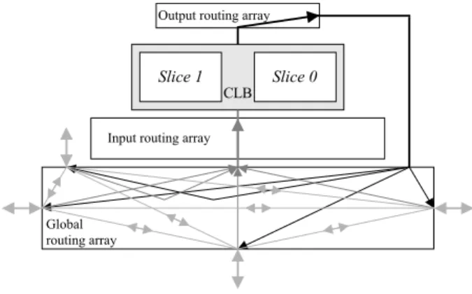
Each CLB has three routing arrays associated: two local arrays (input and output); and one global array. The routing resources in these arrays may be unidirectional or bi-directional, as indicated in figure 4. No routing resources are available in the local arrays to establish direct interconnections with other CLBs, so the interconnections required in the replication process can only be done through the global routing array.
Input routing array Output routing array
Slice 1 Slice 0
CLB
Global routing array
Figure 4. CLB routing resources
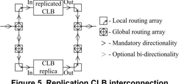
Only unidirectional routing resources are available between local and global routing arrays, as seen in figure 4. For paralleling inputs, interconnection segments between global arrays may be unidirectional (from the replicated CLB inputs towards the CLB replica inputs), or bi-directional. Concerning the outputs, interconnection segments between global arrays may also be unidirectional (from the CLB replica outputs towards the replicated CLB output), or bi-directional, as illustrated in
figure 5. Otherwise, since signals do not propagate backwards, no signals will be presented at the inputs of the CLB replica, and the outputs of both CLBs will not be placed in parallel. As a result, output glitches will occur when CLB replicated outputs are disconnected from the system and no signals will be propagated to the rest of the circuit.
replicated CLB
CLB replica
- Local routing array - Global routing array - Mandatory directionality - Optional bi-directionality In In Out Out
Figure 5. Replication CLB interconnection
Since no fault at any of the replicated CLB inputs may propagate backwards, the logic values presented at the inputs of the CLB will not be affected by the interconnection, even if the replicated CLB is faulty. As such, all CLB replica inputs will always reflect the correct values and hence the state information it acquires is correct as well. As a consequence, and after the replication process, the outputs of the CLB replica always display the correct value, automatically correcting any faulty behavior.
5. Conclusion
This paper presented a novel replication process to replicate active CLBs without disturbing their operation. The proposed procedure enables the implementation of a truly non-intrusive structural concurrent test methodology for partial and dynamically reconfigurable SRAM-based FPGAs, with the following advantages:
1. The test method is completely system-transparent; 2. The overhead at chip level is very low;
3. Test pattern generation has low complexity because it is done for only a single CLB;
4. Fault location is resolved to a single CLB slice; 5. Fault tolerance may be added as a complement of the
proposed solution;
6. The dependability of systems based on this type of FPGAs is improved.
Support to system designers through the whole process implied also the development of specific software tools for the automatic generation of partial reconfiguration bitstreams from their complete counterparts, to simplify FPGA reconfiguration operations through the BS infrastructure.
References
[1] F. Hanchek, S. Dutt, “Methodologies for Toleranting Cell and Interconnect Faults in FPGAs”, IEEE Transactions on Computers, Vol. 47, No. 1, pp. 15-33, Jan. 1998.
[2] J. Lach, H. W. Mangione-Smith, M. Potkonjak, “Low Overhead Fault-Tolerant FPGA Systems”, IEEE Transactions on VLSI Systems, Vol. 6, No. 2, pp. 212-221, June 1998. [3] N. R. Shnidman, H. W. Mangione-Smith, M. Potkonjak, “On-Line Fault Detection for Bus-Based Field Programmable Gate Arrays”, IEEE Transactions on VLSI Systems, Vol. 6, No. 4, pp. 656-666, Dec. 1998.
[4] M. G. Gericota, G. R. Alves, J. M. Ferreira, “Dynamically Rotate And Free for Test: The Path for FPGA Concurrent Test”,
2nd IEEE Latin-American Test Workshop, pp. 180-185,
Feb. 2001.
[5] IEEE Standard Test Access Port and Boundary Scan Architecture (IEEE Std 1149.1), IEEE Std. Board, May 1990. [6] C. Stroud, S. Konala, P. Chen, M. Abramovici, “Built-In Self-Test of Logic Blocks in FPGAs (Finally, A Free Lunch: BIST Without Overhead!)”, Proc. of the 14th IEEE VLSI Test Symposium, pp. 387-392, April 1996.
[7] C. Stroud, E. Lee, S. Konala, M. Abramovici, “Using ILA Testing for BIST in FPGAs”, Proceedings of the International Test Conference, pp. 68-75, Oct. 1996.
[8] C. Stroud, E. Lee, M. Abramovici, “BIST-Based Diagnostic of FPGA Logic Blocks”, Proceedings of the International Test Conference, pp. 539-547, Nov. 1997.
[9] M. Abramovici, C. Stroud, “BIST-Based Detection and Diagnosis of Multiple Faults in FPGAs”, Proceedings of the International Test Conference, Oct. 2000.
[10] M. Abramovici, C. Stroud, “BIST-Based Test and Diagnosis of FPGA Logic Block”, IEEE Transactions on VLSI Systems, Vol. 9, No. 1, pp. 159-172, Feb. 2001.
[11] W. K. Huang, F. J. Meyer, X. Chen, F. Lombardi, “Testing Configurable LUT-Based FPGA's”, IEEE Transactions on VLSI Systems, Vol. 6, No. 2, pp. 276-283, June 1998.
[12] W. K. Huang, F. J. Meyer, F. Lombardi,, “An approach for detecting multiple faulty FPGA logic blocks”, IEEE Transactions on Computers, Vol. 49, No. 1, pp. 48-54, Jan. 2000.
[13] M. Abramovici, C. Stroud, S. Wijesuriya, C. Hamilton, V. Verma, “On-Line Testing and Diagnosis of FPGAs with Roving STARs”, Proceedings 5th IEEE International On-Line Testing Workshop, pp. 2-7, July 1999.
[14] M. Abramovici, C. Stroud, C. Hamilton, S. Wijesuriya, V. Verma, “Using Roving STARs for On-Line Testing and Diagnosis of FPGAs in Fault-Tolerant Applications”, Proceedings of the International Test Conference, pp. 973-982, Sept. 1999.
[15] M. Abramovici, C. Stroud, B. Skaggs, J. Emmert, “Improving On-Line BIST-Based Diagnosis for Roving STARs”, Proceedings 6th IEEE International On-Line Testing Workshop, July 2000.
[16] Politécnico di Torino ITC’99 benchmarks, available at http://www.cad.polito.it/tools/itc99.html