ABSTRACT
The Unmanned Vehicle Systems (UVS) are growing in large proportions and are an emerging technology but there are some limitations that still need to be overcome in order to get the best effectiveness. One of the limitations is the reception area for vehicle operation. Most vehicles operate in of-sight (LOS). A very significant improvement would be to allow behind line-of-sight (BLOS) operation via wireless networks. This thesis proposes to overcome this difficulties using wireless networks: Wi-Fi and third generation (3G) and fourth generation (4G) of mobile networks to operate an Unmanned Ground Vehicle (UGV), also called a rover. This way, the vehicle will not have a theoretical range operation, turning into a vehicle operated in BLOS. This thesis also includes the study of the reliability and efficiency of wireless heterogeneous networks solution for UGVs operation in real time.
As prove of concept for described objectives, an Unmanned Ground System (UGS) was developed. This system is capable of control and monitoring multiple vehicles through wireless networks: Wi-Fi, 3G and 4G mobile networks. The communication between the vehicle and the operator is made through a ground control station (GCS), an Android application running on a mobile device. Its aim is to centralize all the information from the vehicle(s). Present on the vehicle is a Raspberry Pi (RPI) acting like a proxy, thus enabling the communication between the GCS application and the UGV’s board controller, the Ardupilot Mega (APM). The RPI receives telemetry from APM via Micro Air Vehicle Communication Protocol (MAVLink) and captures video through an external camera and sends it all to the GCS.
In order to evaluate the system performance, several tests were done for data collection, namely values of network latency, bitrate, packet error ratio (PER) and signal strength varying with speed, altitude and location of the vehicle.
Keywords: Ardupilot, MAVLink, multiple UGVs, Wireless networks, mobile devices,
RESUMO
Os Unmanned Vehicle Systems (UVS) estão em crescimento exponencial e, como tecnologia emergente, existem algumas limitações que necessitam de ser ultrapassadas de modo a obter uma maior eficácia dos mesmos. Um bom exemplo é o raio de alcance para operação do veículo. Como muitos operam em Line-of-Sight (LOS), uma melhoria significativa seria passar a operá--lo Behind Line-of-Sight (BLOS). Esta dissertação tem como objectivo ultrapassar esta limitação, recorrendo a redes sem fios: Wi-Fi e 3ª (3G) e 4ª geração (4G) de redes móveis para operar um Unmanned Ground Vehicle (UGV), também chamado rover. Desta forma o veículo não terá, teoricamente, um limite de alcance no seu manuseamento. Esta tese também inclui o estudo da fiabilidade e eficácia da solução das redes sem-fios heterogéneas para operar um UGV em tempo real.
Como prova de conceito foi desenvolvido um Unmanned Ground System (UGS). Este tem capacidade de controlar e monitorizar múltiplos veículos através das redes sem-fios: Wi-Fi e redes móveis 3G e 4G. A comunicação entre o veículo e operação é estabelecida através de uma
Ground Control Station (GCS), nada mais que uma aplicação desenvolvida no sistema
operativo Android, executada num dispositivo móvel. No veículo está presente um Raspberry Pi (RPI) a actuar como um proxy, permitindo o estabelecimento da ligação entre a GCS e a placa de controlo do veículo, um Ardupilot Mega (APM). O RPI recebe telemetria vinda do APM através do protocolo de comunicação Micro Air Vehicle Link (MAVLink), captura vídeo através de uma câmara e envia ambos para a GCS.
Por forma a avaliar a performance do sistema, foram executados vários testes para recolha de dados como: latência de rede, ritmo binário, Packet Error Ratio (PER) e potência de sinal. Este foram analisados com a variação da velocidade, altitude e localização do veículo.
Palavras-chave: Ardupilot, MAVLink, múltiplos UGVs, redes sem-fios, dispositivos móveis,
ACKNOWLEDGMENTS
In first place I would like to thank to my family for the opportunity to get the master’s degree, especially my mother, father and sister. The transmitted education was central to finish this dissertation successfully, winning all proposed challenges and all the rest showed up.
I want to thank to my girlfriend who was always present and supported me when I needed the most. Her wise words and advices were a great source of motivation to finish this dissertation. Above all, their friendship was essential at various points along this journey.
Of course, this whole project wouldn’t be possible without the participation of Professor Pedro Sebastião. Always present and active, he helped me out with technical problems inherited to the project (hardware, software and theoretical questions). Their knowledge served often as a key in solving problems related to the proposed objectives. All the work conditions for the realization of this thesis were possible due to its action in an attempt to obtain and always offer the best and most appropriate resources for the development of the project. I want to acknowledge him not only for this labor issues but also for the support and wise words on personal issues. His advices were also a great help and came always on good time.
Also I want to thank Professor Nuno Souto for his technical advices and transmitted knowledge in all areas covered by the developed work.
I would like to thank the Instituto de Telecomunicações because it was part of this project, by helping with the necessary material and physical space to work.
A special thanks to my good friend and colleague Tiago Saraiva, who helped me out with technical questions and for being always present, giving me support.
Another special thanks to my good friend and colleague Gonçalo Horta for his wise words and advices, both in labor and personal issues.
A acknowledge must be done to Autoeuropa/Atec group, namely to Eugenio Bastos, Ricardo Silva, Carlos Isidro, Paulo Galvoeira and José Peniche, for their availability in terms of time and assigned material.
For last but not less important, I want to thank to Huawei engineers Nuno Bernardo and André Mei for their help, active participation, readiness to help and important material for project development.
ACRONYMS & ABBREVIATIONS
2WD Two–Wheel Drive 3DR 3DRobotics 3G 3rd generation 4G 4th generation 4WD Four–Wheel Drive AC Alternating Current ACK Acknowledgment AP Access PointAPI Application Programming Interface
APM Ardupilot Mega
BEC Battery Eliminator Circuit
BLOS Beyond Line-of-Sight
BTS Base Transceiver Station
CAN Controller Area Network
CANH CAN-High
CANL CAN-Low
CDF Cumulative Distribution Function
CIDR Classless InterDomain Routing
CPU Central Processing Unit
CRC Cyclic Redundancy Check
CSMA/CD Carrier-Sense Multiple Access with Collision Detection
DC Direct Current
DC-HSPA Dual Cell-HSPA
DLC Data Length Code
ECU Engine Control Unit
EDGE Enhanced Data rates for Global Evolution
EOF End-Of-Frame
ESC Electronic Speed Controller
FPS Frames Per Second
GCS Ground Control Station
GNSS Global Navigation Satellite System
GPLv3 General Public License version 3
GPRS General Packet Access Service
GPS Global Positioning System
GPU Graphics Processing Unit
GSM Global System for Mobile Communication
HSPA+ Evolved High-Speed Packet Access
I/O Input/Output
I2C Inter-Integrated Circuit
ICE Interactive Connectivity Establishment
ID Identifier
IDE Identifier Extension
IDE2 Integrated Development Environment
IETF Internet Engineering Task Force
IFS InterFrame Space
IMU Inertial Measurement Unit
INS Inertial Navigation System
IP Internet Protocol
IRE Introduction to Research in Engineering
ISO International Standardization Organization
IT Information Technology
ITU-R International Telecommunication Union - Radiocommunication
LAC Location Area Code
LED Lightning Emitting Diode
LLC Logic Level Converter
LOS Line-of-Sight
LTE Long Term Evolution
LTE-A Long Term Evolution Advanced
MANET Mobile Ad-hoc NETwork
MAV Micro Aerial Vehicles
MIMO Multiple-Input Multiple-Output
MNC Mobile Network Code
NAT Network Address Translation
NRZ Non-Return to Zero
OS Operating System
OSI Open Systems Interconnect
OSP Open-Source Project
P2P Peer-to-Peer
PCM Pulse-Code Modulation
PDF Probability Distribution Function
PER Packet Error Ratio
PM Power Module PPM Pulse-Position Modulation PWM Pulse-Width Modulation PX4 Pixhawk RC Radio Control RF Radio Frequency RPI Raspberry Pi
RPM Rotation Per Minute
RTR Remote Transmission Request
RTT Round Trip Time
SoC System on Chip
SOF Start Of Frame
SPI Serial Peripheral Interface
STUN Session Transversal Utilities for Network Address Translation
TCP Transmission Control Protocol
TURN Traversal Using Relays around Network Address Translation
UART Universal Asynchronous Receiver Transmitter
UAV Unmanned Aerial Vehicles
UBEC Universal Battery Eliminator Circuit
UDP User Datagram Protocol
UE User Equipment
UGV Unmanned Ground Vehicles
UI User Interface
UMTS Universal Mobile Telecommunication System
USART Universal Synchronous Asynchronous Receiver Transmitter
USB Universal Serial Bus
UST Unmanned Systems Technology
USV Unmanned Sea Vehicles
UV Unmanned Vehicle
UVS Unmanned Vehicle Systems
VoLTE Voice over LTE
VPS Virtual Private Server
VW Volkswagen
W-CDMA Wide-band Code-Division Multiple Access
Chapter 1
INTRODUCTION
This chapter is directed to all aspects and concepts implied in the realization of this thesis, namely motivation, achieved objectives, scientific contributions and state of the art of the involved technological area. An organized reading is also present in a section relating to the structure of the document.
1.1 Overview
An Unmanned Ground System (UGS) consist on a land system without a human driver aboard that can be controlled remotely. Furthermore if the vehicles have some degree of Artificial Intelligence (AI) they can be self-adaptive to environmental conditions around, smart learning and drive autonomously [1]. In other words, a UGS is composed by the vehicle itself and all the components that are imperatives for its operation [1]. In the military environment, the greatest benefit of the UGSs (and the UVS in general) is the greater protection of the welfare of the operator since he is outside the vehicle [2]. The usage of UGV by the civilian community is growing due to its lower price (also have high prices), easy handling and versatility. For recreation times the remote controlled cars (toys) are a great example. In employment context, there are already some applications, however, are not so well known: land vehicles operating in industrial operations involving risk. An example is drilling in mines where there is risk of collapse, implementation of explosives in quarries, etc.
The control of the vehicle is made by GCS or by remote operator [3]. For this to be possible, the vehicle must have an electronic module that performs the orders given by one of the controllers, that is, receive, translate and send orders to the respective actuators, i.e. an Engine Control Unit (ECU). These necessary components are quite diverse, as described in [3]:
i. Navigation system: Global Positioning System (GPS), magnetometer, barometer and gyroscope, mostly known by Inertial Measurement Unit (IMU), constitution part of Inertial Navigation System (INS). These allows to monitor the vehicle;
ii. Communication system: they can be RC, satellite or wireless systems. These systems provides the connection between the vehicle and the GCS, even in full autonomy cases. There are no low cost modules with high reliability and bandwidth and long range. That is why military use Beyond Line-of-Sight (BLOS) communications, like satellite communication, that allows long ranges, and civilians use RC in Line-of-Sight (LOS) limiting the range of the operation [4][5]. The military uses Ka band (uplink: 27 – 31GHz; downlink: 17.7 to 21.2GHz; bandwidth: 3500MHz) and civilians the Ku band (uplink: 13.2 to 18.1 GHz; downlink: 10.7 to 12.7GHz; bandwidth: 500MHz) [6][7][8]. In way of avoid the satellite communication complexity and the short range of radio control, cellular networks will be used in UGVs control context: Universal Mobile Telecommunication System (UMTS), Evolved High-speed Packet Access (HSPA+), Long Term Evolution (LTE) and Long Term Evolution Advanced (LTE-A). The
connection between systems will not be affected since high transmission rates and low latencies (Round Trip Time (RTT)) are allowed:
Table 1.1 - Transmission rates, network latencies and bandwidths. Source: [9].
Thus, real-time video transmission and control of a BLOS UGV can be done with quality and without the referred problems of the other communication types;
iii. Control system: this is closely related with the communication, using it to control the vehicle, sending and receive commands and video. Usually it is a remote control but it can also be a tablet or a similar device. In remote control, an additional display is needed to show the video and monitored parameters; the tablet (or similar) can do it all together.
1.2 Motivation
The concepts of technology and automobile industry were not always consensual. As two distinct concepts that they were, their merger was something hard to imagine and therefore to accomplish. Over the time, both began to integrate and today their separation is unthinkable, even prohibitive due to their correlation.
Any car manufactured in the last 15 years has incorporated a lot of technology in its operating system. The trend is that the more recent the vehicle is the greater the amount of technology embedded in its system, as well as greater diversity and quality. It is quite important to note that this integration process was possible due to a large investment in both areas, not only the economic but also the employment level.
As such, eventually appear Unmanned Ground Vehicles (UGV), one of the subgroups of the Unmanned Vehicles Systems (UVS). Another well-known example are the Unmanned Aerial Vehicles (UAV) or as they are called among the civilian community “drones”.
The largest investor and driver of UGVs was the military branch. They gather a set of favorable conditions for the development of Unmanned Systems Technology (UST): investment funds by the defense departments of governments, restricted and controlled space (aerial, land and
Feature\Technology UMTS HSPA HSPA+ LTE LTE-A
Downlink [Mbit/s] 384Kbit/s 14 28 100 1000
Uplink [Mbit/s] 128Kbit/s 5.7 11 50 250
RTT [ms] ~150 < 100 < 50 ~10 ~ 5
naval) for testing, research teams, specialized staff and workshops for vehicles construction. UST are evolved in such a way that many military institutions have specific for careers for UGV and Unmanned Sea Vehicles (USV) drivers and UAV pilot [11]. Here we can see the impact that this technology had in this business.
Speaking concretely of UGVs, there are many possible applications for military operations, such as: explosives disarming and threats analysis, surveillance and pursuit operations, access to dangerous zones, discovery of landmines, seek for radiation, search and rescue, space expeditions, etc. Besides de military field, this technology may also be employed in civil and employment context: agriculture (analysis and treatment of crops), civil engineering inspection, fire combat, hobby, photography and video capture, timber industry (cutting and transport), mining operations, etc. Of course that many of these applications can be employed in military branch.
In UGVs control and monitoring the transmission of telemetry and real-time video is mandatory. As the video will be the eyes of the driver, this has to have a minimum acceptable quality. The UGVs used for military operations are controlled via satellite communication because access to this type of communication is very limited, which leads to greater system security. But satellite communication has an associated problem that can, depending on application type, derail the system functioning: significant delay times. The UGV systems for civil applications doesn’t use satellite communication because it’s not feasible in this context, both in monetary terms and in ease of access. Instead, Radio Control (RC) is used, and the vehicle has to be in LOS, limiting its range. For real-time driving, both these communication schemes are unviable. A possible solution that can remove the disadvantages of each of these communication types is the use of 3G and 4G mobile networks. These technologies allow multiple operators (e.g. 1 pilot and 1 camera operator), multi-vehicle control and control of vehicles regardless of the location of vehicles and operators. The problems of long delays in satellite communications detrimental to driving real-time applications and the limited scope of the RC communications are exceeded. However, mobile communications have also some associated problems due to:
• Mobile networks: maximum bit-rate, loss of coverage, handovers; • Packet network usage: latency.
The notable developments in the market of mobile devices (smartphones and tablets) and its applications has brought a new paradigm for applications that were only developed for
computers, where the user had limited mobility as it needed to have a fixed location with access to the Internet. Mobile devices provides all the necessary components and features for the system architecture: mobility, GPS, Bluetooth module, wireless communication modules (HSPA+, LTE, Wi-Fi), processing capacity, receiving and sending video, friendly User Interface (UI), sensors data, among others. Thus no need to have a processing unit coupled with modules apart. This way, the system will be transparent regarding the location of the vehicle and driver.
The alliance between the automobile industries and mobile networks increasingly efficient, brings a new paradigm: remote driving with easy access. Nowadays the youth community has easy access to driving simulation applications and to racing games through their smartphones or tablets. This fact allows these young people to react in a natural way when faced with real driving situations. An excellent example of a similar situation is the aircraft pilots’ case: they have to meet a certain number of flight simulation hours before moving to a real situation.
1.3 State of art
The market of UGVs is rising every day and it brings not only new vehicles but also new software/hardware solutions. For military/security purpose these solutions are classified and little is get to know about them. In the case of civilian use new hardware and software solutions for UGVs emerge at high rate, as proprietary projects or OSPs. These projects were developed by companies or academic groups and includes the whole UGS: vehicle, communication, control and monitoring modules.
1.3.1 Controller boards
Many companies have chosen to develop their own UGVs, making them proprietary UGVs. Autonomous Solutions Inc. is a company that develops ground robotic solutions, i.e., UGV command and control software and technology for farming, mining, governmental and automotive areas worldwide [12]. ASI offers a multi-vehicle and user friendly software for unmanned vehicles command and control – the Mobius [13]. The Nav™ Automation Kit was also developed by ASI and allows a manual control vehicle to be controlled robotically [14]. Its area of action are remote control, teleoperation and full automation.
Mechatroniq Systems Inc. is an American company that designs and produces UVS and all related technologies [15]. The MissionPlanner is a software developed for planning paths and
control and monitoring remotely the Mechatroniq’s UGVs [16]. The MEC is a small controller board built around and ARM Cortex A8 processor that provides remote sensing applications and autopilot the vehicle (and others) [17]. Minu is a board with GPS with active antenna, temperature sensor and advanced sensing technology with 9 degrees of freedom and is applied on robotics, vehicle orientation sensing and position, asset tracking, dead reckoning and precision of autonomous vehicle guidance [18].
Sterela developed the 4MOB for applications like monitoring, inspection, external operations and agriculture tasks/construction [19]. It is a UGV with already considerable scale, speed and payload capacity [19]. For control, a radio control is used but route planning is also possible. This vehicle provides video surveillance and teleoperation [19].
Parrot has created the Jumping Sumo, a mini UGV controlled by a mobile application via Wi-Fi connection [20]. This vehicle is targeted to hobbyists, however it is possible to ingrate in other types of applications.
There are many more, those 4 are just an example. Proprietary systems have the advantages of ensuring technical assistance but they are quite directive, not offering flexibility for other kind of applications than that for which they were designed. In turn, the OSPs are very flexible (i.e. allow adaptation to the desired application) and have a big worldwide community that provides hardware configurations, software, tutorials, tests results, etc. A great example of that is the DIY Drones community [21] that support all kinds of unmanned systems.
The objective of the controller board is, as the name implies, to allow control of the vehicle whether it is manual control, semi-automatic or fully autonomous. However, with the exception of the manual mode, the incorporation of a GCS is required so that all information be centralized. In these cases the controller boards have a GCS, where is possible to send and receive commands and receive and request telemetry information.
It is safe to assume that Ardupilot is the most well-known and used in the world of OSPs [22]. Its versatility is the main reason why it is one of the most used platforms for UVS control. Based on Arduino it is also easy to handle and has a friendly IDE to program [23]. It Is available for download software for desktops that act as a GCS: Mission Planner and APM Planner. Both are able to control and monitor vehicles through Xbee modules. In addition to the described software, there are still GCS applications for Android OS: Andropilot and DroidPlanner [24][25].
Pixhawk was projected to integrate in an easy way with better safety features and to improve reliability compared to present solutions [26]. This platform uses computer-vision algorithms to implement control of the vehicle through on-board image processing [27]. It provides a GCS called Qgroundcontrol that allows vehicle control, parameters setting and missions planning. At the present time, Pixhawk is known as the improvement of APM 2.6 (the most developed version of APM so far).
Openpilot was developed by hobbyists and uses a modified version of FreeRTOS operating system. In addition to providing a GCS called Openpilot GCS, this platform is constituted by CC3D and CopterControl boards [28].
Paparazzi is an autopilot platform that support all configurations of Micro Aerial Vehicles (MAV). Designed to be a low cost solution this platform provides the Paparazzi GCS for monitoring and control (allows pre-programmed missions and others flight modes) through radio systems [29].
Mikrokopter is and autopilot system developed for multi-rotor configurations: quadcopter, hexacopter and octocopter [30]. Provides a GCS, the KopterTool, allowing pre-programmed mission and telemetry transfer. Like Ardupilot, Mikrokopter also have an Android application: BUDwise.
KKMulticopter is aimed at the hobbyists who do capture of aerial images using quadrotors [31]. A very basic system developed for leisure activities. For this reason, it has no GCS, but is provided a tool for firmware transmission to the board [32].
MultiWii was developed by RC hobbyists and uses Arduino framework and Nintendo Wii sensors [33]. It was designed for multi-rotor configurations. It has a GCS, the MultiWii WinGUI and an Android application, the MultiWii EZ-GUI that only allows the change of board parameters [31].
Aeroquad is similar to MultiWii and is also based on Arduino. It was designed for multi-rotor configurations and provides a GCS only for parameters modification [34].
It is important to refer once more that it is possible to shape the board to the desired application. In some definitions of some boards come references to multi-rotor vehicles, hexacopters, etc, since this was its original purpose. However, since they are OSPs, it is possible to develop firmware for the desired application and execute it on the board.
Speaking specifically on projects that make use of cellular networks to control and monitoring UGVs, there are some studies prepared, as mentioned in [35] and [36] but none is a commercialized product. Apart from this type of study, there are no known marketable and/or implemented projects that perform control functions and monitoring of a UGV using the cellular network.
1.3.2 Covered areas
1.3.2.1. Control
The control of a UGV can be done via an application software or a remote radio controller. Each one of them can be designed to use a specific type or communication technology and operate in a certain network topology. The most common applications at civilian and OSPs level uses a RC controller and most recently mobile applications via wireless communications (Wi-Fi and mobile). In military case, the control is made via satellite communications and specific software and hardware developed by them self or private companies. For example, Oshkosh Defense Corporation develop the Command Zone™ [37] technology to operate remotely (and also monitoring) a ground vehicle using laptops, on-board displays or digital devices. It is not possible to access more detailed data about military projects, due to its important value in defense.
1.3.2.2. Monitoring
Monitoring must indeed be made using a display where the information is presented. What is unusual is the change in the type of display depending on the technology used, e.g. in mobile applications makes sense to make the mobile device display, in cases of use an RC remote usual use a laptop computer or other type of monitor. At military level the monitored parameters are extensive and some with some adjacent complexity, e.g. Oshkosh TerraMax is a technology equipped with ground-penetrating radar and mine roller systems [38], and these are complex technologies. In civil use the complexity of the monitoring system will depend on the type of applications: leisure will be a simple system but for industrial it will be a complex system.
1.3.2.3. Mobile applications
In terms of mobile applications for ground vehicles, nothing that offers simultaneously real-time control and monitoring via mobile networks. In military sector there is no knowledge of any type of mobile application directed towards the UGVs.
In the civil branch already begun to appear aimed applications for the control of UGVs, e.g. the FreeFlight 3 for Jumping Sumo by Parrot [39]. This application uses the private Wi-Fi network of the vehicle. There are some applications but only for monitoring and control a set of actuators (driving it is not possible). These enter the automobile context and the following are the ones most outstanding:
•
“Audi Mileage Tracker” by Audi [40];•
“BMW i remote” by BMW [41];•
“OnStar RemoteLink” by General Motors [42];•
“Chevrolet Volt” by Chevrolet [42];• “Nissan Leaf app” by Nissan [42]; • “Hyundai Blue Link” by Hyundai [42].
1.3.2.4. Communication
Wireless radio communication for UGVs typically utilized three distinct radios in way to provide the capabilities described in Table 1.2. The commands are sent to UGV using wireless technologies, such as Internet or ZigBee [43].
Radio Capability Description
Data Transmission Transmits control signals from operator to UGV
Video Transmission Transmits analog video from UGV to operator
Emergency Stop Transmits signal to disable UGV
Usually, radio technologies are designed to have a balance between its 3 most relevant requirements: bandwidth, latency and signal propagation [44]. If it was possible to use only one channel, capable of encoding the video and combine voice with data the system, it would be much less complex, reducing size, weight and power consumption.
The transfer of telemetry and video is essential for UGV control and monitoring. Table 1.3 presents the imperatives for network data traffic in UGVs operation. Many types of
communication and network topologies can be thought for that purpose. In the remaining sections will be presented some points of view within that context.
1.3.3 Application areas
The UGSs technology was and is the target of a major investment [1][2], not only for military but also for civilian use. These systems have several of applications that may not be as intuitive at first sight. UGVs can replace humans and go to places where they can’t [46]. For example, UGVs can be used as:
• Monitor and manager for crop conditions during the growing season [47][48];
• Wild fire surveillance, providing sensor data for fire detection and the ability to notify the fire forces in case of fire [49];
• Scientific research of any kind of nature (atmospheric, pollution, environmental, etc) [49];
• Boarder interdiction, patrolling the borders [49];
• Law enforcement, patrolling dangerous areas for manned operations [49];
• Disaster and emergency manager, providing real-time surveillance in hazardous environments [49], e.g. in coal mines, to avoid disasters and consequently high risk rescue operations (usually the used communication technologies are ZigBee along with RC due to its efficiency and low cost) [50][51];
• Industrial applications, such as surveillance of pipelines or nuclear factory [49][52]; • Detector of chemical agents, explosive, volatile gases and radiation [53];
• Explosives disposal [54].
Data Traffic Delay Tolerance Jitter Tolerance Bandwidth
Requirement
Real-Time Sensing Low Medium Low
Store-and-forward
sensing (offline storage) High High Low
Command and control Low Medium Low
Real-Time video Low Low Very High
Store-and-forward
pictures High High High
Store-and-forward video High High Very High
1.4 Objectives
The aim of this dissertation is to study the implementation of system capable of control and monitor, locally and remotely, a UGV using wireless networks: Wi-Fi and 3G and 4G mobile networks, more specifically UMTS, HSPA+, LTE and LTE-A. In this context the following goals were defined:
• Development of a system for control and monitoring multiple UGVs through an open-source flight controller and Android mobile application;
• Structure a generic and modular system but robust enough, to allow the insertion of new features since this area is in exponential growth, which leads to constant changes; • Overcome the delay problems related to wireless communications in real-time
applications, in this case operate a UGV;
• Development of an Android application that will act as a GCS, centralizing all the telemetry and receive video stream;
• Connection establishment between the GCS app and the vehicle;
• Evaluate the designed system’s efficiency through test fields and analysis of collected data.
1.5 Contributions
As explained before in section 1.4 this thesis proposes a low complexity system capable of control and monitoring multiple vehicles (greater focus on UGVs). Designed to be a very complete platform, it is also user-friendly and easy to implement. The system includes the vehicle construction and the development of several applications:
• Remote GCS: Android application for UGV control and monitoring;
• Routing Server: java program that will allow the communication between Remote GCS and the vehicle;
• RPI Camera: shell script that provides the camera to stream video from RPI to Remote GCS.
Note that the RPI is also running other application besides RPI Camera: MAVProxy. This software was developed by Andrew Tridgell and it is open-source. This way the RPI can be seen as a relay server between the vehicle (APM more precisely) and the Remote GCS. The use of this open-source software is connected with the fact that the APM uses Micro Air Vehicle Link (MAVLink) protocol to communicate. As result, a study of MAVLink and UGVs was done.
It is worth mentioning that implementing the waypoint protocol and parameters protocol, both constituent parts of MAVLink, was not an objective. However, they were implemented, making it a more complete project.
As a scientific contribution, a set of 2 articles were elaborated, with special focus on chapters 3 through 8. Once completed, 1 was submitted to a conference (Conftele 2015, published) and the other will also be submitted to a conference or international scientific magazine or journal.
1.6 Dissertation structure
In this section the dissertation structure is presented. The dissertation is composed of 8 chapters: • Chapter 1 – Introduction: current chapter;
• Chapter 2 – Unmanned Ground Systems: presents the main modules of an UGS; • Chapter 3 – Dimensioning an Unmanned Ground Vehicle, comprises the explanation of
the assembly of the vehicle used in this project, i.e. its constituent modules and the way they operate.
• Chapter 4 – Boards: explains the boards that are used on the system, its operation mode and characteristics;
• Chapter 5 – Communications: covers all the communications types used, brief explanations and protocols;
• Chapter 6 – Control and Monitoring Applications: presents and explains all applications used to operate the vehicle, mainly the Remote GCS;
• Chapter 7 – Results and Evaluation, shows the results obtained through field tests, treated so that its analysis is easy and as intuitive as possible;
• Chapter 8 – Conclusions and Road Ahead: presents the conclusions to be drawn from the system performance, through all the results and in what way they will matter towards the future.
Besides that, there are 6 annexes at the end of the document that contains a more detailed explanation about subjects that comes up across the document: Annex A for raspberry versions and specifications; Annex B that contains the structure of a MAVLink message; Annex C for describe MAVLink internal protocols; Annex D for an explanation about the control mechanisms; Annex E that contains a message diagram for a communication example; Annex
Chapter 2
UNMANNED
GROUND
SYSTEMS
Here will be specified the main blocks of an Unmanned Ground System and thereafter described point by point. All possible technologies for each block are referred as well as the existing blocks inter-relation in the system.
2.1
Introduction
An UGV is set by several blocks that work together for proper operation of the vehicle. The malfunction of one of these modules has negative implications on the system and may even lead to irreparable damage in case of accident. Each block has its task and has to fulfill it correctly. Therefore, it is not possible to assign valuable degrees to each, because a malfunction of a block has direct implications on the system operation. Almost 100% of the time all modules are working together, waiting for each other’s results in order to make decisions or complete its cycle. These blocks are properly identified on Figure 2.1.
2.2
Ground Control Station
The GCS is the physical module through which the user communicates to the vehicle, being able to edit parameters, see telemetry information and send commands [44]. In other words, it can be seen as the cockpit of the vehicle where it is possible for the user to perform all actions as if he was present inside the vehicle [55], the human-robot interaction. GCS can have many forms, sizes and shapes and consists on a sensor station and a pilot (at least) [4]. Normally it is running on a computer (or more) or other(s) device(s) with processing capacity, allowing interaction between the operator(s) and on-board systems [55]. The pilot gives commands and the servo system of the vehicle executes the corresponding actions, this way the vehicle avoids
Figure 2.1 – Main blocks of a UGS composition. Adapted from: [4].
UGS
Communication Control Vehicle Control Station Navigation Poweralgorithms and shows some intellect [56]. Therefore, the communication is indispensable for GCS functioning. The GCS allows the operator to determine the future positions of the vehicle – real-time control and mission control. This last element will cause a reduction on reliance of satellite communication for BLOS operation [56].
2.3
Communication
The wireless communication is a mandatory factor to operate an Unmanned Vehicle (UV). This is one of the reasons why improve these systems is a hard task. Table 1.2 on Chapter 1 shows that different radio links are used, fact that adds complexity to the system, augmenting the minimum requirements. In order to simplify the communication a single radio channel can be used to transmit video (coded through digitizing) and data and voice combination [44]. The GCS transmits commands, vehicle video and data in a closed loop link (the information is not shared with other networks). The communication link is of extreme importance since the operator must maintain the control of the vehicle all the time. A communication breakdown can lead to dangerous situations, such as the vehicle destruction (and others, depending on the type of application). The implementation of sail safes can be a way to remedy the problem, like return to the start point or home in case of communication loss. However, all current unmanned vehicles are on par with the same communication problems: low availability of transmission channels and the amount of data that they could handle, resilience of Radio Frequency (RF) subsystems against interference and spectrum allocations. [57].
Investments made in UGVs and the increased use mean that its communication system must be developed to support the new capabilities added to new vehicles. With the communication systems evolution, it is expected that they will be more efficient, simple to use, smaller and
lighter. Usually, UGVs use RF communication, being highly integrated into their architecture. That RF communication is usually limited to unlicensed frequency bands, e.g. 2.4GHz that are very susceptible to interference with other wireless communications operating at the same frequency band [44]. To avoid interference problems, higher frequency bands can be used, which supports higher data rates and wider bandwidths for real-time operation and video streaming with minimum acceptable quality. However, lower frequencies propagate better than higher frequencies, limiting the vehicle range operation, both in LOS and BLOS. The wireless communications, namely cellular, suffered from big improvements from the last years. Larger bandwidths, higher transmission rates, lower delays and higher coverage are the main improvements of these networks. The integration with tablets, smartphones and other computing platforms and the fact that the infrastructures are already implemented (no need of investment) made this market even more appealing to the world of unmanned systems. It is an inevitable fact that one the operation of unmanned vehicles will be performed through cellular networks. Table 2.1 represents the communication evolution from 2011 to 2020, both technology and capability improvements.
Teleoperated vehicles require very high transmission rates, low latencies and high reliability communication systems. The 4G of cellular networks, namely the LTE–A, is capable to provide those features when in good/medium conditions (see Table 1.1).
2.4
Power
The power subsystem is responsible for supporting the energy requirements of the entire system. The discharge rate is a key element for choosing the right power system. Depending on the vehicle application the power system will vary. The sources go from fuel cell, solid oxide
fuel cell, batteries subsystems through hybrid solutions. Usually, fuel solutions are used on heavy vehicles and cargo vehicles where there needs to be a great responsiveness to the total weight. To this end high torque engines powered by liquid or solid fuel are usually used. However, if fossil fuels are used (traditionally gasoline and diesel), the issue of environmental pollution enters the picture. Hybrid solutions can take an important role in the transition from fossil fuels to system powered by batteries and other renewable energy sources (e.g. solar, wind,
etc). But both solutions have the same challenges: performance is affected by the weight and
bulk of expendable fuel. At present, small unmanned vehicles use almost exclusively batteries, namely lithium batteries, since they are rechargeable an environmental-friendly. Small UGVs do not require the torque specifications seen in the heavy ones. Those are the typical combinations, however heavy vehicles can use batteries and small vehicles can use fuel. The selection of the appropriate power source must take into account the UGV application with the features of using each type of power supply (i.e. noise of the engine work, maximum duration of the source power, etc). For example, if a UGV is used for surveillance or spy, this should be small, silent and have a medium/high energy autonomy – use batteries; however, if the terrain is difficult or the distance to cover is high the batteries may not be enough and fuel subsystems can take the place.
The current unmanned vehicles have minimum requirements related with power suppliers in order to be efficiently operated: they must be reliable, energy dense and rechargeable. Besides that, these power supplies must satisfy a set of safety and environmental rules.
The battery market is in constant evolution and nowadays good performances can be achieve. In fact, at least 90% of civilian branch will use some kind of battery to power his vehicle [58]. There are many kinds of batteries and, again, its usage will depend on the type of application. Lithium batteries dominates this area and are constant present on small UGVs [44], replacing the Nickle Cadmium (NiCad), Lead Acid and Nickle Metal Hybrid (NiMH). They are very popular due to its real high energy density and have a power capacity which allows the vehicle to operate for an acceptable period of time. However, they have to follow a comprehensive and rigorous range of safety and environmental protection rules [44].
The technological advances in power systems, UGS and automotive industry leads to a new kind of vehicles that have begun to be something usual: electric and hybrid vehicles. Due to its batteries and super capacitors they have enough energy to move great distances.
2.5
Navigation
The navigation system of a UGV includes a set of modules that helps on vehicle navigation. Usually, UGV uses a combination of GPS and INS [59]. The INS is composed accelerometers that detects motion and gyroscopes that detects rotations. Through estimations of speed and time intervals between previous locations, the vehicle position can be calculated. This process is known as “dead reckoning”. However, INS has some tendency to an error known as "drift". In order to correct this error a GPS is used and so the INS/GPS combination allows to determine the vehicle current position and orientation. Global Navigation Satellite System (GNSS). Although, GPS receivers can be vulnerable to jamming, as GPS signals can be target of “spoofing” (type of hacking attack), that disrupts the vehicle navigation by sending false signals. That is why the security, availability, robustness and capacity of command links are of utmost importance.
Currently, GPS is the most used GNSS, but there are others. Galileo is the European global satellite-based navigation system and Glonass the Russian GNSS [60]. These 3 GNSS are nevertheless 100% interoperable with each other, giving not only a bigger coverage of available satellites but also a better performance than in the case where only one of the technologies used or a combination of two of them [61][62]. Crossing the triple signal frequencies from each technology with each other will improve the accuracy of the navigation system [63][64].
For teleoperated vehicles the GPS/INS combination is not enough. In addition those vehicles must have a video stream through each the operator will control it. The video will be his eyes, and it is sent through a processing unit. In military branch the radar is also a possibility, making possible to see further and avoid obstacles in motion or stopped. For this, it is most valuable.
2.6
Vehicle
The UGVs don’t have specified configurations or standards. The type of application will dictate the vehicle size, shape, weight and configuration. Main block of an UGV are identified on
Figure 2.3. Usually an UGV has 4 wheels and can be Two-Wheel Drive (2WD) or Four-Wheel
Drive (4WD) (see Figure 2.4). There are others who do not have wheels and their locomotion is made using the same mechanism used in tanks and industrial machinery – continuous track, also known as tank tread or caterpillar track (see Figure 2.5). There are even cases where legs are used. The engine is responsible for transforming the energy received from the energy module in rotation to the wheels.
Figure 2.3 – Core modules of an UGV. Adapted from: [65].
Body
Frame
Suspension
Mount
Whell
activator
Steering
wheel
Brake
mechanism
Engine
2.7
Control
UGVs control is based on a board that processes all received commands and sends orders to the respective actuators (control). Usually this board is a unique piece but there is the possibility to have two boards, each one dedicated to a function: one for control and other for processing. The commands that this module receives are usually sent by a traditional RC that operates on commercial band or military band (Ka and Ku bands) or microcomputer user interfaces (e.g. keyboards, mice, joysticks and touchscreens). However, the increasing use of mobile devices in the last years (see Figure 2.6) as lead to a new paradigm. Mobile devices are becoming more constant in human life and as such, are taking the place of the traditional RC commands.
Figure 2.6 – Global mobile devices growth. Source: [65]. Figure 2.5 – Example of a continuous track UGV. Source: [5].
The UGV’s autonomy is related with the degree that operator has on vehicle operation. It can be quite diverse, as the vehicle can be controlled manually (no autonomy) or be completely autonomous and intelligent. There are several standards that define the levels of autonomy of an UGV. This level will depend on task difficulty, environmental complexity or required operational time [62].
As shown in Figure 2.7, the trend follows towards vehicles completely autonomous, but this does not mean that they are best suited for all types of applications. Each type of application may require certain features or functionality that a particular navigation mode offers exclusively or in a better condition.
Manual remote control in LOS requires a radio technology for communication. This mode provides direct control of throttle and steering. In teleoperation it is also possible and the user operates the vehicle BLOS using a video stream in real-time (the video will be the eyes of the operator), from which he gives feedback. The semiautonomous mode consists on establishing a pre-programmed mission and the vehicle executes it when ordered to. The vehicle uses its sensor system to guide itself. Full autonomous UGVs perform tasks without the guidance of an operator, reducing his work and increasing the performance in bad or limited communication conditions. In full autonomous mode the vehicle is capable of adapting itself to the surrounding conditions and make decisions without the need of an operator using all its systems.
Chapter 3
DIMENSIONING
AN UNMANNED
GROUND
VEHICLE
Dimensioning an UGV is not as simple as it sounds.This chapter describes the main challenges of this process and matches the modules described in Chapter 2 to the material used in the development of the system.
3.1
Introduction
The process of dimensioning an UGS is a complex process, contrary to what one might think. The reason why is due to an exponential increase of unmanned systems and its applications in real-world situations. It has become common to find these systems performing actions that in the past were done by humans or manned systems. This increase leads to a higher level of complexity when talking about dimensioning an UGV.
The major challenges that this process faces are [67]:
• Interoperability: every component has its own features and characteristics as well as associated problems. Thus all system blocks must operate seamlessly with each other and the system itself with other manned and unmanned systems;
• Communications: current UGS demand a high degree of human interaction. As result, those communication links must have protection since the information that flows on it is critical to vehicles operation. Therefore, the reliability of those links are also a very important factor. In case of miscommunication the system has to be prepared to react and activate fail safe mechanisms. However, the fewer failures there are, the more reliable will the system be. This has to contemplate mechanisms that provide reliability to the system or at least improve it in some way (e.g. communication protocols, redundancy mechanisms). In general, the challenges at this level are security, spectrum availability, bandwidth and link range;
• Training: the operation of an UGV could be a complex process. In order to improve this process training could be considered as a requirement before operating an UGV in real-world applications which more responsive actions (e.g. in the case of aeronautical piles, they have to perform a certain number of flight simulation hours before flying a real aircraft);
• Autonomy: depending on the type of application, the autonomy level will vary. The higher the autonomy level, the greater will be its complexity (for development and implementation). The implementation of autonomy in vehicles will reduce the necessary bandwidth.
3.2
Vehicle main blocks
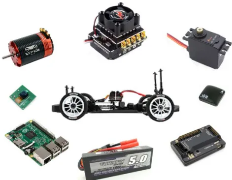
The vehicle is an integrated part of the developed system. Figure 3.1Figure 3.1 – UGV composition
on-board components that are also part of the whole system. Each component is described in more detail on the following sections of the current chapter.
3.2.1 Frame
A four wheel configuration was chosen whose drive system uses these 4 wheels for locomotion,
i.e. the vehicle is 4WD. The frame has a suspension system which, together with the 4WD
feature with front/mid/rear differential, allows the vehicle to be operated in difficult terrain. It is possible to adjust Toe, Camber and shock position. Camber angle is the angle made by the wheel when viewed from the rear or front of the car [68]. The camber can be positive, neutral or negative as shown in Figure 3.2. Toe is related with the direction the wheels are pointing
Figure 3.1 – UGV composition and all on-board components.
when viewed from above [69] (see Figure 3.3). The tie rod and camber are made of steel, which increases the reliability; the big bore shock is made of aluminum and has 17mm. The frame itself is made by a combination of plastic and aluminum. This part has, by default, own locations for engaging the other vehicle components: motor, batteries, Electronic Speed Controller (ESC) and RC receiver (default communications system). With the cover on, its dimensions are: 305mm width, 200mm height and 530mm length.
3.2.2 Motor
When electric schemes are used, it is customary to use one of two types of electric motors: brushed or brushless. In the present case, a sensorless brushless motor was used. To understand how brushless motors work it is important and easier to first perceive how brushed motors (often referred as canned motors) operate. Every brushed motor consists of the following parts [71]:
• Armature: set of the poles, terminals and the commutator. It is basically the rotating portion of the motor.
• Poles: electromagnets formed by cooper wires wrapped around pieces of metal and attached to the armature. Almost all motors have 3 poles to prevent the battery from shorting out (lowering efficiency) and to prevent the motor from getting stuck;
• Commutator: copper section that acts like a switch on the armature, reversing the current to the poles every half rotation. Thus, rotation is maintained by the magnetic fields of each of the poles;
• Brushes: device that is wired to the battery and promote the transfer of electrical power to the armature by touching the commutador;
• Magnets: two permanent magnets with opposite polarity are attached inside the motors case (or ‘can’);
• Armature: set composed by the spinning shaft wrapped by wires, the poles and the commutator.
In Figure 3.4 it is possible to identify each of the constitution part of a canned motor and also helps to understant its operation mode. The battery is directly wired to the brushes that make contact with commutator plates as the armature spins, charging a particular pole (electromagnetic) [72]. Applying energy to a electromagnet will cause it to polarize, one end becomes the north pole and the other the south pole. As the north poles of two different magnets are automatic repelled, the armature will spin so its north pole faces the south pole of the ‘can’ magnets. The commutator switchs the polarity of each pole everytime the pole passes a magnet. Like the armature spins, the electrical charge applied on it will flip and the poles will be again repelled, the armature spins again and consequently will rotate the pinion gear and the vehicle’s transmission.
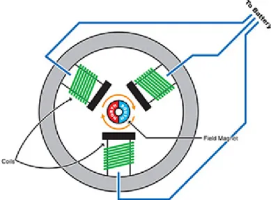
Now comes the explanation for brushless motors. Their construction is similar to the brushed motors, except the poles (electromagnets) are stationary (no need for brushes) and everything is “inside out” [71] as shown is Figure 3.5. Here the permanent magnets are placed around the motor shaft becoming part of the spinning portion. This grouping is known as rotor. The coils are a place around the inside of the ‘can’ motor to generate many and differente magnet poles. These motors can have sensors on the rotor that sends signals back to the ESC – sensored
brushless motors. Note that electric motors are rated kV (RPM per Volt). E.g. a motor with 3500kV will spin 3500 RPM for each volt applied on it.
Speaking about the advantages and disadvantages of both types of motors, the difference is noticeable. Brushed motors have many associated disadvantages: the brushes and the commutator wear out and must be cleaned from time to time, the friction between the brushes causes to shorter run time, battery life, slows down the motor and lows the power to weight ratio [71].
1 4 LiPo battery cells in series.
2See Figure 3.6.
Feature Measure
kV (RPM/v) 2100 Weight (g) 239 Continuous Current (A) 80
Max Current (A) 140 Resistance (ohm) 0 Max Voltage (V) 15 (4S) 1 Power (W) 2100 Shaft A (mm) 2 5 Length B (mm) 2 70 Diameter C (mm) 2 42 Can Length D (mm) 2 62 Total Length E (mm) 2 87
Figure 3.6 – Specification of motor dimensions.
Source: [73].
Figure 3.7 – Motor assembled on the vehicle frame.. Figure 3.5 – Construction model of a brushless RC electric motor. Source: [72].
The vehicle is provided with a 2100kV brushless motor represented in Figure 3.7. Its specifications are set out in Table 3.1. Besides those characteristics, this motor is compatible with any sensored or sensorless ESC and is sensor-based which allows and excellent torque and low-speed drivability. In case of failure it is possible to replace the rotor since it is removable. This kind of motors offers an outstanding performance and are resistant: high purity cooper windings, sintered neodymium magnet and aluminum ‘can ’motor. They are designed for vehicles who need good RPM and reliability. A disadvantage of brushless motors are their power consumption. As they are quite rotary they will consume some power when operate in medium/high rotations.
3.2.3 Electronic Speed Controller
The Electronic Speed Controller (ESC) is an electronic circuit responsible for varying the speed, direction and dynamic brake of an electric motor. This circuits transforms the electric current that comes from the power system in a rectangular signal with a specific width that varies with the amount of energy that enters the system. By other words, the ESC converts Direct Current (DC) from battery to Alternating Current (AC) which is required by the motor. The signal is modulated using Pulse-Width Modulation (PWM), i.e. the pulse has always the same maximum and minimum amplitude and the duty cycle it is the only variation. That means ESC allows the signal to control the torque and speed of the vehicle. Modern ESCs incorporate an electric component that regulates the voltage for the receiver: a Battery Eliminator Circuit (BEC) or Universal Battery Eliminator Circuit (UBEC). These components convert battery voltage to 5V which is the voltage to which the receiver operates.
There is an ESC for each type of electric motor [74]:
• For brushed motors: the ESC simply limits the amount of energy delivered to the motor. To do this, the ESC sends only short pulses (short pulses, less power, slower the motor spins). The ESC is connected with the motor by two wires. To reverse the motor’s direction, simply swap the wires.
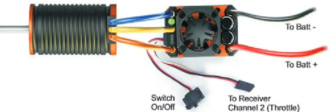
• For brushless motors: the power is controlled in the same way, however the ESC must electronically choose one of the windings in the motor to make it turn. The most recent brushless ESCs are known as sensorless ESCs and determine the position of the motor using the generated voltage in the momentarily unpowered windings. The ESC is
connect with the motor by three wires, like shown in Figure 3.8. To reverse the motor’s direction, simply swap the two of the wires.
The vehicles uses a 120A waterproof and sensorless ESC, which is represented by Figure 3.9.
Table 3.2 resumes all its relevant features.
Table 3.2 – ESC features. Source: [76].
Feature Measure
Continuous Current (A) 120 Burst Current (A) 140 Resistance (ohm) 0 Battery compatibility 2-4 cells LiPo
BEC output (V/A) 6/3
Running mode Forward with reverse
Weight (g) 141
Length (mm) 43
Width (mm) 39
Height (mm) 33
3.2.4 Servo
Servos (or servo motors) are electric rotary motor that control the position, velocity and acceleration of machine part with great precision. They are very used by RC community due to its energetic efficiency, precision, reliability and low price. Its existence eliminates the need to have a complex and expensive control system.
A servo is composed, as shown on Figure 3.10, by [77]:
• Small DC motor: heart of a servo that is attached by gears to the control wheel. Moves the gears and the main shaft;
Figure 3.9 – ESC coupled on the vehicle. Figure 3.8 – Connection between the ESC and the motor. Source: [75].
• Drive gears: reduces the motor rotation, gives more power to the main shaft and move the potentiometer with the main shaft;
• Potentiometer: connected to the servo’s output, records the motor rotations (its resistance changes);
• Control circuit: regulates with precision how much should the motor rotation and in which direction.
The servo position is controlled by electric pulses of variable width, also known as PWM. There are 3 important variables to take into account: minimum pulse, maximum pulse and repetition rate. Usually a common servo only turns 90º to each direction (180º in total). The neutral position is where the servo has the same amount of potential rotation in both clockwise and counter clockwise direction [78]. The PWM received by the motor will determine the shaft’s position based on pulse duration. When the shaft reaches the desired position the servo holds that position. If an external forces tries to rotate the shaft while the servo is holding a position, the servo will resist from moving out that position. Torque rating is the name given to the maximum amount of force that a servo can exert. The motor expects to receive a pulse every 20ms in order to determine the desired position, even if it is the same as the actual (the pulse must be repeated to instruct the servo to hold) [78]. Example (see Figure 3.11): a 1,5ms pulse will make the motor turn to the 90º position: if the pulse is shorter than 1,5ms the motor moves to 0º; otherwise it will move to 180º.
The motor’s speed is proportional to the difference between its actual position and the desired position: proportional control [78]. The speed at which the motor will run depends on the necessary speed to accomplish the task: it can turn fast or slowly.
To control the position of the output shaft it uses the PWM technique. The control line feeds the servo with the pulse. This line does not supply power directly to the motor. Inside the servo there is a control chip that receives the pulse and so it does not receive much current.
In this particular case, this component is responsible for the vehicle’s steering and can handles 12Kg.
3.2.5 Power source
To power the system, LiPo batteries were chosen. This type of batteries are used in many consumer electronic devices. They gained popularity in RC industry on the last years and now are the 1st choice. The wide array of benefits they offer justifies that fact. However, each user must evaluate and decide if the benefits overweight the drawbacks. LiPo batteries inspire special care and if they are properly met there will not be any problem (at least it should not). Those cares will be described later.
Before using a LiPo battery it is necessary to understand its specifications and associated concepts. Each battery has a label which contains relevant information to know exactly how it should be used. On Figure 3.12 it is easy to identify the specifications of a LiPo battery. The capacity of a LiPo battery measures how much power the battery can hold. The unit of measure is mAh (milliamp hour). Basically, it gives how much current can be drained from the battery to discharge it on an hour. In other words, determines the usage time of a battery before it recharges (higher capacity leads to higher run time). Usually a motor drain is discussed in
Amperes (A) and the conversion from mAh to A can be done: 1000mAh = 1A (Ampere) [80]. UAVs do not have a standard capacity value. In turn, the UGVs typically use 5000mAh. It is correct to say that, if possible, batteries with higher capacities should be used. However, we should be bear in mind that the higher the capacity the greater the size and battery weight. Choosing the right LiPo should take it into account the motor and ESC specifications.
The LiPo battery cells as nominal voltage of 3.7V. A battery with 7.4 volts means that it has 2 cells in series (2S battery pack). A three-cell (3S) pack is 11.1V, a four-cell (4S) pack is 14.8V and so on. The voltage determines the vehicle maximum speed. It directly influences the RPM of an electric motor. With 2S LiPo the motor will spin 25900 RPM, with a 3S LiPo will spin 38850 RPM, and so on.
Every battery type has its discharge rating (or C rating). It can be seen as the measure of how fast the battery can discharge without risks. But it is a bit complex to understand because it is not a stand-alone number: it is necessary to know the battery’s capacity to figure out the safe current draw. Knowing the capacity it is time for simple math: 20C = 20 x Capacity (in Amperes). Having the battery of Figure 3.12 as example, C rating = 20 x 5 = 100A. The result of this operation corresponds to the maximum sustained load that a battery can safely handle. If in some case a higher current is provided, the battery will degrade faster or will burst into flames. So, it is very important to charge battery with the right current and voltage values. The variable C rating spoken so far corresponds to continuous current. However, batteries have another “C rating”, this time associated with burst rating. As in the previous case the current is continuously supplied, in this case it is applied in 10-second burst [80]. Moreover, the mode of operation is identical. This concept does not comes into play when the vehicle is at steady speed, but when it accelerates. Usually, burst rating is higher than continuous rating. The burst rating is used to compare batteries, not the continuous rating.
LiPo batteries are very powerful but need special care, especially on charge and discharges processes. Reading the instruction manual before use is recommended.
Chapter 4
BOARDS
For UV applications the “flight” controller is an essential part without which was not possible to flight or run. Usually only one board with processing and control capabilities is used, but in this case two boards are used, one for each task.
4.1
Introduction
Flight controllers can be considered a major part in setting up a UVS, since it will be through this board that the control and monitoring of the vehicle are made. For this purpose, an Ardupilot Mega (APM) 2.6 was used, running the ArduRover firmware. The APM is the most known flight controller among the hobbyist community because it is an OSP, which means that there is much of information available on matters relating to the board, especially on the Internet. Despite being a very complex component, the APM does not allow connection to a wireless network. In order to promote this mandatory connection is used a Raspberry Pi (RPI) 2 model B. A Universal Serial Bus (USB) dongle can be coupled to the RPI and therefore access a wireless network. It also allows coupling of a video camera, capture video and sending it to the operator via a video stream.
In short, instead of having one board performing control and processing tasks, there will be two boards: APM for control and monitoring; RPI for processing and internet access.
4.2
Ardupilot
4.3.1 Overview
APM is a pro-quality IMU autopilot based on Arduino Mega, developed by 3DRobotics (3DR) and licensed by GNU General Public License version 3 (GPLv3) [81]. As referred before, APM is the most known “flight controller” among the hobbyist community. It can fly aircrafts (fixed-wing, multicopters or helicopters) and drive rovers or boats, depending on which firmware is chosen. Since UGV and the term “flight controller” does not fit well, from now on APM refers to the autopilot controller board (or simply autopilot). This autopilot board offers a waypoint based navigation, manual navigation, GPS navigation, camera control and a two way telemetry flux. When used in aircrafts (fixed-wind or multi-rotor) it is capable to automatically stabilize the vehicle. The MAVLink is used to communicate in both directions: inside and outside. This protocol is explained further in Chapter 5.
Until today, there are 4 APM versions. The APM 1.0 is set by 2 boards: the APM board, which actually is an Arduino Mega for Input/Output (I/O) pins and processing; the other one is an IMU shield with all necessary sensors for navigation [82]. Sometime later it was decided to merge the 2 boards of version 1.0 and then form APM 2.0. Thus, APM version 2.0 is the set of an APM board, navigation sensors, processing unit and I/O pins [83]. However, it still needs a shield composed by a magnetometer, a GPS and a slot for micro SD card. Then came the new
![Figure 2.1 – Main blocks of a UGS composition. Adapted from: [4].](https://thumb-eu.123doks.com/thumbv2/123dok_br/18396639.893656/24.892.261.630.394.779/figure-main-blocks-ugs-composition-adapted.webp)
![Figure 2.2 – Example of GCSs. Source: [4].](https://thumb-eu.123doks.com/thumbv2/123dok_br/18396639.893656/25.892.114.787.250.496/figure-example-of-gcss-source.webp)
![Figure 2.3 – Core modules of an UGV. Adapted from: [65]. BodyFrameSuspensionMountWhell activatorSteering wheelBrake mechanismEngine](https://thumb-eu.123doks.com/thumbv2/123dok_br/18396639.893656/29.892.268.630.111.492/figure-core-modules-adapted-bodyframesuspensionmountwhell-activatorsteering-wheelbrake-mechanismengine.webp)
![Figure 2.6 – Global mobile devices growth. Source: [65].](https://thumb-eu.123doks.com/thumbv2/123dok_br/18396639.893656/30.892.249.637.119.469/figure-global-mobile-devices-growth-source.webp)
![Figure 2.7 – Evolution of UGV control system. Source: [62].](https://thumb-eu.123doks.com/thumbv2/123dok_br/18396639.893656/31.892.148.739.276.619/figure-evolution-ugv-control-source.webp)
![Figure 3.4 – Operation of a traditional brushed RC motor. Source: [72].](https://thumb-eu.123doks.com/thumbv2/123dok_br/18396639.893656/37.892.246.658.248.533/figure-operation-traditional-brushed-rc-motor-source.webp)
![Figure 3.10 – Servo composition. Source:[78].](https://thumb-eu.123doks.com/thumbv2/123dok_br/18396639.893656/41.892.205.677.299.581/figure-servo-composition-source.webp)
