419 Fernando Luiz Câmara Campos Junior
http://orcid.org/0000-0002-8131-9624 Mestrando
Universidade Federal de Ouro Preto - UFOP REDEMAT
Ouro Preto - Minas Gerais - Brasil [email protected]
Sebastiana Luiza Bragança Lana
Professor-Titular
Universidade do Estado de Minas Gerais - UFMG Professor do Curso de Pós Graduação na REDEMAT
Belo Horizonte - Minas Gerais - Brasil [email protected]
Paulo Santos Assis
Professor-Titular
Universidade Federal de Ouro Preto - UFOP Escola de Minas
Departamento de Engenharia Metalúrgica Ouro Preto - Minas Gerais - Brasil [email protected]
Benito Barbabela e Silva
Engenheiro de operação e processos na VALE Nova Lima – Minas Gerais - Brasil
Abstract
The induration furnace is one of the most important devices in the pellet produc-tion system. It is responsible for ensuring the quality of pellets produced, since a high level of thermal energy is necessary to reach the physical properties needed. Therefore, the refractory lining performance is important to guarantee the quality of pellets and to avoid thermal losses. Minor failures in the refractory lining may result in serious damage, if it not previously identified and repaired. This article was written to explain a preventive technique to identify and repair such minor issues with the refractory lin-ing before escalation. The use of this technique in the proper frequency may result in furnace life cycle extension.
Keywords: pelletizing; refractory lining; thermography.
1. Introduction
Pelletizing furnace refractory
lining life cycle extension by
applying thermography analysis
and direct refractory injection
http://dx.doi.org/10.1590/0370-44672017710163
Metallurgy and materials
Metalurgia e materiais
The production of iron ore and steel has significantly expanded in recent years, particularly in developing coun-tries such as China and India, resulting in a large increase in the demand for iron ore. The quality of iron ore deposits has been deteriorating worldwide and the existing mines are facing increasing difficulty in producing high grade ores (NOMURA, YAMAMOTO, FUJII, & TAKIGUCHI, 2015).
Since 1950, it has been possible to observe that there is an increasing occur-rence of low grade material. Such mate-rial requires more complex beneficiation steps to concentrate and so, at the same
time, more ultrafine iron ore (pellet feed) needs to be processed, mainly in the new projects (MOURÃO, 2008).
The pelletizing process was devel-oped in 1912 by A. G Anderson and C.A Brackelsberg (CAPPEL & LUNGEN, 1999) and consists in agglomerating the ultrafine iron ore, bellow 0.045mm, in order to achieve a product with suitable size distribution to be used directly in reduction reactors.
The processed material of a pellet-izing plant is called pellets, and is made of ultrafine iron ore agglomerated by using discs or drums forming green balls (YAMAGUCHI, FUJII, YAMAMOTO,
& NOMURA, 2010).
The iron ore pellet quality is ob-tained when mechanical resistance is added to the agglomerates. This property is obtained by the thermal treatment of pellets in the Travelling Grate furnace (ATHAYDE, TAVARES, NUNES, & FONSECA, 2004).
420
cooling zone, cool air is pushed through the burnt pellets and the resultant hot air is conducted back to the burning stage for heat recovery.
The furnace is a metal structure coated with refractory lining, designed to endure heat to the order of 1350ºC.
The downward gas flow at the temperature of about 1350ºC raises the pellet temperature levels. As a thermal source, considering the travelling grate technology, burners are positioned later-ally in the firing zone using natural gas or oil as fuel. The burners use preheated air at the temperature of about 1000ºC to perform the combustion. The recovered duct positioned above the firing zone
guarantees the homogeneous flow of preheated air to all burners.
All properties of the agglomerate are obtained during firing. This step is therefore crucial to ensure the quality of the produced pellets (MEYER, 1980).
The heat recovery system depends a great deal on the refractory lining performance, as the insulation provided is responsible to minimize the heat ex-change with the atmosphere. Therefore, in case of refractory damage, the insula-tion fails, resulting in energy consump-tion increase and a possible escalaconsump-tion of structural problems.
Minor cracks are capable of lead-ing to heavy structural problems in the
refractory lining, and if such problems are not identified in the early stage, they can result in structural collapse of the furnace, causing furnace life cycle reduction.
The refractory lining condition is the main indicator to determine the exact time and duration of major shutdowns. Normally, such interventions take 20 to 30 days to complete.
Refractory lining condition moni-toring is crucial to avoid premature problems as well as structural collapse. Moreover, the application of correct measures to effectively avoid such problems might lead to a furnace life cycle extension.
2. Materials and methods
Infrared thermography is a preven-tive and predicpreven-tive maintenance tool, figuring as a promising tool for fast and reliable condition monitoring, among other non-destructive inspection and
test-ing techniques available (MAYERKAR, KOTMIRE, WAGH, & SHINDE, 2016).
By observing the heat patterns in op-erational system components, cracks can be located and their seriousness evaluated.
In this study, a thermographic cam-era FLIR series E30 was used to obtain detailed information about the furnace’s inner surface temperature. Figure 1 shows the thermographic camera used.
Figure 1
Thermographic camera series E30 of FLIR and Typical thermal profile possible to find in across the burner chamber refractory of a pelletizing furnace.
The measurement program was based upon a map of critical regions
pointed out by the maintenance pro-gram and process staff. The criticality
of the points were ranked according to Figure 2.
The thermographic measurement was done 6 times in a period of twelve months to follow the evolution of the inner surface temperature level.
To avoid the increase of inner surface temperature, refractory mass was injected in the critical points,
identified with thermography.
To inject the refractory mass, a very simple manual device was used. The injectable mass was selected with the same chemical quality of the re-fractory lining.
For the mass injection, a hole is
bored through the furnace structure in the area where hot spots were detected, using an industrial drilling machine and a 12mm drill bit. The re-fractory mass is then injected through the bore by pressure.
Figure 2
421
3. Results and discussions
According to the procedure, Figure 3 presents the results of the last 4
mea-surements.
Therefore, the thermography
results indicate degradation of the re-fractory lining condition.
Figure 3 Summary results of the recent inspections.
By examining the results, it is possible to verify that the hot spots were located mainly in the corners of the structure, indicating that most
failures in the refractory lining start at its borders.
This trend must be considered in the inspection planning, ensuring that
these regions are always included in the thermography path. Figures 4 and 5 illustrate that situation.
Figure 4 Thermography made in the primary cooling.
422
In summary, the hot spots identified are presented in the scheme in the Figure 6:
Figure 6
Hot spots in the furnace.
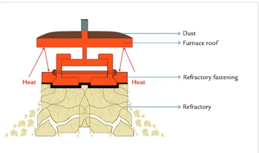
In an attempt to understand the reasons why hot spots are happening, besides cracks in the refractory borders, it was possible to conclude that the dust
accumulated on the inner furnace surface prevents the heat exchange with the at-mosphere, reflecting the head back to the refractory fastening and lining.
Figure 7 shows the scheme of the cracks’ evolution due to the prevention of heat transfer between the structure surface and atmosphere air.
Figure 7
Cracks evolution due to dust
accumulation on the structure surface.
Therefore, the cleaning of the sur-face structure is a factor as important as the refractory wear out. Therefore, a periodic cleaning must be done to avoid crack formation/evolution in the refractory lining.
To repair the refractory lining issues, a mass injection was made in the hot spot areas to block the evolu-tion of cracks and to reduce the tem-perature in these regions identified in the thermography.
The main idea of the mass injec-tion is to fill the cracks with refractory mass, taking advantage of the process temperature to make quick solidification, thus blocking the crack evolution as per the scheme in the Figure 8.
Figure 8 Mass Injection.
A double-check was conducted to verify the effectiveness of the actions
taken. According to the results, all 12 hot spots identified were recovered
423 Figure 9
Before/after in the primary cooling and firing zone.
(a) (b)
Thermography was used as a tool of great effectiveness to identify the hot spots on the furnace structure surface. More-over, Thermography makes the preventive inspections easier because some areas in the furnace are difficult to access.
Thermography also helped to make these inspections frequently, as the equip-ment is very easy to operate and the
information can be easily manipulated to identify the points that needing attention. When using Thermography results, combined with the mass injection tech-nique developed, it is possible to avoid the refractory lining crack evolution, as well as to avoid the refractory and the furnace structure collapse.
Therefore, Thermography used
to-gether with the Mass Injection technique demonstrated our procedure to be an effective preventive tool. As long as it is performed with proper frequency, it can be used to identify and repair refractory lining issues, thus increasing the life cycle of the furnace.
The application of this method yields the results shown in the Figure 10:
Figure 10 Furnace life cycle forecast.
From historic data, normally the furnace campaign is around 4.3 years. Using the preventive methods in this
document, it is probably possible to reach more than 7 years of life. This result has a very high impact in the total
operational cost, energy consumption and pellet quality.
4. Conclusions
Thermography is a very versa-tile method and was used to identify the hot spots showing practicality and assertiveness.
The mass injection method is a very simple technique and perfectly performed the task of filling cracks, avoiding crack propagation and further
issues with the refractory lining and furnace structure.
The cleaning of the roof is very important to avoid crack formation in the refractory lining and must be done with proper frequency.
Therefore, the utilization of the 2 techniques combined results in a
power-ful preventive tool, allowing fast, easy and assertive execution.
424
References
ATHAYDE, M., TAVARES, R., NUNES, S., FONSECA, M. Avaliação da distribui-ção de gases em fornos de pelotizadistribui-ção da Samarco Mineradistribui-ção através de CFD e validação experimental. Tecnologia em Metalurgia, Materiais e Mineração, v.11, n.4, p.340 - 345, 2004.
CAPPEL, F., LUNGEN, H. Historical review of developments in sintering and pel-letizing techniques. In: SEMINAR ON SINTER AND PELLETS. Bruxelas: IISI - International Iron and Steel Institute, 1999. p. 12 - 31.
MAYERKAR, P., KOTMIRE, N. J., WAGH, M., SHINDE, N. Review on ther-mographic analysis of PV panels/system using the infrared thermal cameras.
International Journal of Scientific Engineering and Applied Science, v.2, n.4, p.135 - 139, 2016.
MEYER, K. Pelletizing of iron ores. Berlin, Düsseldorf: Heidelberg Springer-Verlarg, 1980. MOURÃO, J. M. Estudo prospectivo do setor siderúrgico: NT minério de ferro e
pelotas, situação atual e tendências 2025. Brasília: Centro de Gestão e Estudos Estratégicos, 2008.
NOMURA, T., YAMAMOTO, N., FUJII, T., TAKIGUCHI, Y. Beneficiation plants and pelletizing plants for utilizing low grade iron ore. Kobelco Technology Review,
p. 8 - 15, 2015.