On the Applications of a Compact Autonomous
Acoustic Recorder
Cristiano Soares
a), Celestino Martins
a), Friedrich Zabel
a), Ant´onio Silva
b)a)MarSensing Lda., Centro Empresarial Pav. A5, Campus de Gambelas, 8005-139 Faro, Portugal
b)
Institute for Systems and Robotics, University of Algarve, 8005-139 Faro, Portugal
e-mail: {csoares, cmartins, fzabel}@marsensing.com
Abstract—A number of acoustic A compact acoustic recorder,
primarily designed for underwater noise monitoring, is presented in this paper. The Self-Register Hydrophone has been used in several occasions during the past three years, in underwater noise monitoring activities. However, this kind of device also find application in other areas such as array processing and passive acoustic monitoring of marine mammals. An overview on the application of the Self-Register Hydrophone is given herein.
I. INTRODUCTION
The increasing concern on the impact of industrial noise in the world’s aquatic and marine environments is generating an ever increasing need to establish procedures for protecting sensitive areas. Several countries are now making significant legal steps in order to routinely include underwater noise measurements in environmental impact studies of industrial activities newly installed in littoral waters, as an attempt to understand the possible negative impacts of man-made noise on the marine fauna, specially on cetaceans and some species of fish, and whenever possible to take action on mitigating malicious effects. Understanding the impact of noise on the marine fauna, implies to systematically carry out in situ acoustic data acquisition and the development of effective measurement strategies.
The conjugation of these needs with rapid advances of electronic parts and lithium battery technology are perhaps the most contributing factors for the development of acoustic data loggers in the past 10 years. Intense research and the rapid development of commercial activities around this problem are significantly increasing the demand of acoustic recording devices with suitable operational characteristics. These char-acteristics include large autonomy and storage capacity, small size, and attractive pricing, specially from the point of view of commercial companies. Accessory functionalities, such as the inclusion programmable operation may significantly improve the operationality of these devices. In recent years a number of research laboratories and commercial companies have made autonomous acoustic recording devices available, which, to large extent, is targeting underwater noise monitoring and marine mammal tagging [1], [2].
The Self Registering Hydrophone is a compact autonomous acoustic recorder that has been prototyped and employed in several activities related to Environmental Impact Studies and scientific projects since 2008. Over the past 3 years, this acoustic recorder has demonstrated an extensive versatility in
the sense that it has been a significant factor for the design of effective measurement strategies, due to its funcionality and easy availability of multiple units. It responds to a widespread tendency where miniaturized and portable devices are required for allowing small teams, often of one or two person, to carry on there activities when reduced material resources are available to cover a large area (let’s say 10 km×10 km). This paper describes this new recording device, and reviews a number potential applications of this device, including underwater noise monitoring, acoustic inversions, and passive acoustic monitoring of marine mammals.
II. THE AUTONOMOUS HYDROPHONE
The initial objective was to design an acoustic acquisition device for application in underwater noise monitoring activ-ities, which should be small and light, and easy to operate at sea. The design of this device took into account several conflicting aspects requiring a compromise, including small size and attractive price, data storage size, acquisition sample rate, and autonomy.
A. The Hardware
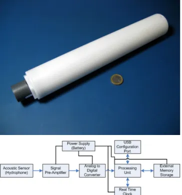
The autonomous hydrophone is a compact cylinder with a length of 323mm and a diameter of 50mm. The cylinder is fab-ricated from Delrin which is very robust both mechnically and also resistant to sea-water. Including the hydrophone, interior electronics and battery the total weigth dos not exceed 0.7kg. Normal operational depths for the autonomous hydrophone is up-to 100 meters, greater depths are however possible. Figure 1 shows a simplified internal block diagram of the device. The selected hydrophone is a model SQ-26 from Sensor Technology Limited which has a nominal electrical sensitivity of -193.5 dB re 1 V / 1 µPa, and a flat response in the frequency range 1 Hz to 28 kHz. The hydrophone pre-amplifier has a nominal bandpass gain of 30 dB for the frequency range 122 Hz to 24.9 kHz. A Programable Gain Amplifier (PGA) is placed before the Analog to Digital converter (ADC) and has adjustable gains in the range 1×, 2×, 4×, . . . , 64×. These settings allow the autonomous hydrophone to record signals with a maximum rms pressure level of approximately 172 dB
re1 V / 1 µPa, and 136 dB re 1 V / 1 µPa with the PGA set to 64. Analog signals are sampled by a 24-bit delta-sigma ADC at a standard rate of 50781 samples per second with the option to use 101562 samples per second. To extend the operational
Fig. 1. The Self-Register Hydrophone. Top panel: photograph. Bottom panel: block diagram.
time of the hydrophone only the 16 most significant bits of each sample are processed and stored. An embedded system microcontroller stores the acquired samples on a industry standard removable flash card. The current flash card uses 2 GByte in size. This can, however, be extended permitting longer periods of operation. A single exchangable lithium-ion type 18650 3.7 V battery is used to power the autonomous hydrophone for up-to 15 hours on continous acquisition or up-to 80 hours of standby when using a lower acquisition duty cycle. The autonomous hydrophone is fully programable through the external USB interface, this is also used to set the internal real time clock. A magnetic switch present inside the hydrophone allows for optional control of acquisition without the need to open the container - an advantage when operating in wet conditions.
These technical characteristics reflect the compromise of the initial objective which is to have a system for daily operations with rapid deployment, recovery and re-deployment scenarios. The main compromise is the use of high sampling frequencies versus flash storage capacity, and also energy autonomy of the system. The use of a 2 GByte flash card at a sampling rate of 50781 Hz allows for 5h 40min of continous acquisition. An advanced feature for acquisition scenarios where multiple autonomous hydrophones are setup as an acoustic array the current hardware permits, through the use of an external cable setup, the syncronization of all independent acquistion systems through an external clock interface.
B. The software
The software consists of an embedded acquisition pro-gram that controls the data acquistion according to several configurations that are previously setup by the user. The acquisition program controls the start and stop of acquisition, programming of gain, retrieval of sampled data from the ADC and storage of data on the external flash card. The program also uses the included USB interface for the reception of configuration settings from another electronic device, usually a PC laptop with a standard serial communication programs. Configuration possibilities include a user defined timetable which is used to control acquisition based on the internal real time clock, length of each acquisition file, PGA settings and a descriptive text for the operation. All files are stored on the flash card as standard audio files ready for use in applications. An additional feature is the storage of information related to the acquisition, like sampling frequency, sea trial description, PGA settings, sample size and real time clock directly in the header of the audio file for easy posterior analysis.
III. APPLICATIONS
The first prototype of the autonomous hydrophone was finished during 2008. Since then, it has been used in several occasions, primarily in underwater noise monitoring, where it has demonstrate to be a convenient tool to operate under different experimental designs. This section discusses the possibilities for the employment of this device in different scenarios.
A. Underwater noise monitoring
The observation of man-made noise often aims at character-izing the influence of the noise radiated by a given source as a function of distance, and eventually azimuth. This may imply to take recordings at many positions in the area of interest, which usually is carried out from a boat or small vessel, or simultaneous recordings at multiple positions.
The autonomous recording device presents a convenient solution both for moving and moored operations: since the signal acquisition completely takes place inside the cilindric case, no cable connecting the acoustic sensor to a recording device is required. This is advantageous in comparison to cabled recorders, since even at mild maritime conditions it is dificult to avoid punches on the hydrophone cable and waves hitting the boat, which will generate noise with signifcant contributions to the received sound level. Figure 2 shows examples on how deployments can take place with an au-tonomous recorder. In assisted operation the device is attached to a rope, with a small weight at the bottom, suspended from a subsurface float, in order to maintain the rope tense, and most important, to decouple the submerged components from the waving. This in turn is attached to a surface float in order to allow the system to drift away from the boat, for minimizing the noise of waves hitting the boat. The photograph in Figure 2 shows an example of a deployment in this configuration.
Another operation mode is by mooring the recorder (see Fig. 2), which is required for multiple simultaneous recordings, for
Fig. 2. Deployments of the autonomous receiver. Top panel: deployments for assisted operation from boat, and moored deployment; bottom panel: for assisted operation the hydrophone is allowed to drift away, in order minimize the noise of waves hitting the boat.
long monitoring periods, or if the human presence is impos-sible or undesired. In a mooring configuration the recorder attachment is similar to that in drifting configuration, except that a larger ballast is necessary. In this case the surface float is to mark the deployment position.
B. Acoustic inversion applications
Many classical acoustic inversion problems are based on coherent processing of multichannel acoustic data. This re-quires time-synchronization. The most common systems with time-synchronized acoustic channels have a central module with a multi-channel acquisition unit. This requires wiring all acoustic receivers for power-supply and transmission of the received signals to the acquisition unit, adding subtantial complexity and weight. Additionally, the central module will hold batteries and electronics, resulting often in an overall system that is difficult to maneuver.
Based on an autonomous recorder design, this complexity can be relaxed in different degrees. One can start with a virtual array composed of multiple autonomous devices, such as the Self-Registering Hydrophone, by introducing an external clock interface for time synchronizing all individual receivers with a common clock. The only cable connecting the hydrophones is the cable carrying the clock signal. The remaining features related to data acquisition, data storage and power supply remain unchanged. This is a significant advantage in terms of reduced wiring, and avoiding the transmission of analog
Fig. 3. Experimental setup for the transmission of acoustic signals: the acoustic receiver is moored, and the acoustic source is towed away over a straight line.
signals in parallel cables, which often is a source of signal degradation due to cross-talk.
The next step for relaxing the multi-channel acoustic system is to eliminate time-synchronization. Thode et. al have used a 3-element vertical array of individual receivers without time-synchronization to perform coherent processing of acoustic data for marine mammals tracking [3]. They exploited the coherence of ambient noise to perform measurements of clock-drifts. In another context, during the Yellow Shark 95 exper-iments, Siderius et. al [4] used incoherent transmission loss taken from acoustic data collected from portable 4-element vertical arrays in a 120 m shallow-water environment to perform geoacoustic inversions. This exploited the sensitivity of the transmission loss observable to variations of geoacoustic parameters.
The actual Self-Registering Hydrophone has been employed in an even more relaxed operation, where only a single receiver was available, with the objective of performing acoustic data inversion for acoustic modelling in the scope of noise moni-toring activities off the Portuguese West Coast near Praia de Mira, Portugal [5]. Using a single receiver implied to repeat the acoustic signal transmissions from several positions for a given ocean transect in order to obtain a overall unique acoustic field capable to provide information on the propagation channel. Figure 3 depicts the experimental setup employed for acoustic signal transmissions. The acoustic receiver was moored at a depth of 7 m at a location with a 13 m watercolumn, and the acoustic source performed acoustic transmissions from a small boat moving away from the receiver. The deployment depth was 5 m and range was increased by 250 or 300 m after each transmission up to 4 km. The transmissions consisted of multi-tones in the frequency band 250 to 1500 Hz. This was repeated for 3 transects, with directions North, West, and South. It took two working days to complete the three transects.
For the purpose of data inversion, the roles of the acoustic source and receiver were swapped as to resemble that all transmissions were made at the receiver position and that a long horizontal array has been deployed over each acoustic transect. The acoustic inversion was posed as optimization problem where the observed transmission loss and and replica transmission loss from candidate models are compared to min-imize mean square error criterion over the horizontal range. The search procedure took place with a genetic algorithm,
1 1.5 2 2.5 3 3.5 4 −70 −60 −50 −40 −30 Range (km) TL (dB) 250 Hz Real data Independent best MAP estimate RMSEMAP = 1.7dB 1 1.5 2 2.5 3 3.5 4 −70 −60 −50 −40 −30 Range (km) TL (dB) 750 Hz Real data Independent best MAP estimate RMSEMAP = 1.0dB 1 1.5 2 2.5 3 3.5 4 −70 −60 −50 −40 −30 Range (km) TL (dB) 1250 Hz Real data Independent best MAP estimate RMSE MAP = 1.4dB 1 1.5 2 2.5 3 3.5 4 −70 −60 −50 −40 −30 Range (km) TL (dB) 1500 Hz Real data Independent best MAP estimate RMSE MAP = 1.0dB
Fig. 4. Comparison of observed transmission loss of the North transect with modeled TL: observed TL (black); best model of each independent GA population (gray); maximum a posteriori model (red).
and included geoacoustic parameter, and source and receiver depth. As the search algorithm is random, for each transect 10 independent populations were started. Finally, the solution was obtained by maximizing empirical marginal probability density functions of the search parameters, whose data is generated by taking candidate solutions of the final GA generations [6]. As an example, Fig. 4 shows the adjustment obained for the North transect, where the TL data for some frequencies is compared to the replica TL computed for the best model of each independent population, and the replica TL computed for the MAP estimate. Also the RMSE calculated for each frequency is indicated.
Figure 5 shows the empirical marginal distributions for each parameter of the inversion obtained for the North transect.
1500 1520 1540 1560 1580 1600
Up. Sediment speed (m/s)
1550 1600 1650 1700 1750 1800
Lo. Sediment speed (m/s)
0 0.2 0.4 0.6 0.8 1 Sediment att. (dB/λ) 2 4 6 8 10 12 14 Sediment thickness (m) 1600 1650 1700 1750 1800 1850 1900 1950 2000 Sub−bottom speed (m/s) 0 0.2 0.4 0.6 0.8 1 Sub−bottom att. (dB/λ) 5 5.5 6 6.5 7 7.5 8 8.5 9 Source depth (m) 4 4.5 5 5.5 6 6.5 7 7.5 8 Receiver depth (m)
Fig. 5. North transect: empirical probabilty functions for geoacoustic and geomatric parameters.
Sediment parameters and geometric parameters present the most compact distributions, indicating that these are the most influent for transmission loss. These results are very consis-tent with the estimates obtained for the other two transects, reinforcing the validity of this approach.
C. Passive Acoustic Monitoring
Passive Acoustic Monitoring (PAM) is the use of vocal-izations of marine mammals, to infer their presence in a given area and behavioral states. PAM has been established as an interesting complement to visual surveys, offering several advantages, since the marine mammals remain submerged for large periods.
The application of PAM techniques with autonomous recording devices is advantageous, allowing for continuous monitoring without the presence of boat and personel, which in turn reduces the dependency on wheather conditions, con-tributes for less disturbance of the subjects, and reduces operation costs. This requires an autonomy of several days or weeks, and a large bandwidth ideally up to 150 kHz. To achieve such specifications very high sampling rates are necessary, and the acoustic data must be stored on a hard-disk, and a relatively large battery-pack is required.
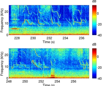
The Self-Register hydrophone may present a solution for the installation in sites close to coast with accessible by a short boat trip, or estuarine regions. It is able to store signals in a mid-frequency range up to 25 kHz, allowing for recording vocalizations of dolphins related to some behaviors. Figure 6 shows time-frequency plots of dolphin vocalizations recorded near a beach in the West Coast of Portugal, in the presence of several vessels involved in a marine construction. Two
Fig. 6. Time-frequency representation of dolphins’ vocalizations recorded off the West Coast of Portugal.
harmonics can be observed for each whistle, where the first harmonics have present a frequency range from 7 kHz to 15 kHz, and the second harmonic present exactly the double frequencies. Above 15 kHz several click trains are observed, in both panels, and in the bottom panel a very low signal vocalized by one of the individuals is observed in the interval 253 to 254 seconds.
It is clear that with the actual observation band provided by the Self-Register hydrophone significant signal components will be truncated. However, these plots emphasize the excellent quality of the received acoustic data.
IV. CONCLUSIONS
This paper has presented the development of an autonomous acoustic recorder, and has made an overview of several subject where this type of device finds application. The main subjects treated herein are applications in underwater noise monitoring, for which it was primarily designed, acoustic inversions and passive acoustic monitoring of marine mammals.
This compact device presents an interesting solution for underwater noise monitoring activities for its small size, which enables simultaneous operation of several units, both in an assisted manner, or unattended in a moored configuration.
It can also conveniently used by scientific groups interested in performing experiments in acoustic inversion, requiring easy transportation, reduced human and material resources, and easy operation. Using autonomous devices for array processing problems may impose severe limitations that can be overcome with readily proposed processing techniques.
Future work shall include increasing the sampling frequency and memory space of the self-registering hydrophone, as the actual specification in bandwidth is not well adapted to the acoustic observation of cetaceans.
REFERENCES
[1] W. C. Burgess, P. L. Tyack, B. J. Le Boeuf, and D. P. Costa. A programmable acoustic recording tag and first results from free-ranging northern elephant seals. Deep Sea Research Part II: Topical Studies in
Oceanography, 45(7):1327 – 1351, 1998.
[2] M. P. Johnson and P. L. Tyack. A digital acoustic recording tag for measuring the response of wild marine mammals to sound. Oceanic Engineering, IEEE Journal of, 28(1):3 – 12, Jan 2003.
[3] Aaron M. Thode, Peter Gerstoft, William C. Burgess, Karim G. Sabra, Melania Guerra, M. Dale Stokes, Michael Noad, and Douglas H. Cato. A portable matched-field processing system using passive acoustic time synchronization. Oceanic Engineering, IEEE Journal of, 31(3):696 –710, July 2006.
[4] M. Siderius and J.-P. Hermand. Yellow shark spring 1995: inversion results from sparse broadband acoustic measurements over a highly range-dependent soft clay layer. J. Acoust. Soc. America, 106(2):637–651, August 1999.
[5] C. Soares, F. Zabel, and C. Martins. An acoustic inversion technique using a single autonomous hydrophone: Experimental results. In Proc.
of the INTERNOISE 2010 conference, Lisbon, June 2010.
[6] P. Gerstoft and C. F. Mecklenbr¨auker. Ocean acoustic inversion with estimation of a posteriori probability distributions. J. Acoust. Soc. Am., 104(2):808–819, 1998.