12 mm Thick Circular Blanks of Al-killed AISI 1020 Steel -Applied for Cylindrical Cup Manufacturing by Multistage Deep Drawing with Simultaneous Ironing
Anil Kumar Paridaa, Shatrughan Sorenb*, Raghu Nandan Jhaa, Sanjoy Sadhukhanc
aMetal and Steel Factory, Ishapore, 743144, India
bDepartment of Fuel and Mineral Engineering, Indian School of Mines, Dhanbad, 826004, India cDepartment of Metallurgy and Materials Engineering, Indian Institute of Engineering Science and
Technology, Shibpur, Howrah, 711103, India
Received: January 4, 2016; Revised: May 17, 2016; Accepted: June 24, 2016
In this paper a new modiied processing route has been proposed for producing long cylindrical cups from 12 mm thick circular blanks of AISI 1020 steel (Aluminium (Al) -killed). In this route, lat blanks were made to preformed shape by stamping operation, followed by multistage deep drawing processes(without blank-holder and with inter-stage stress relief annealing) to increase cup depth. Wall ironing was also purposefully included in each draw step to reduce wall thickness and earing tendency on cup edges. Thus, evolution of wall thickness distribution, Drawability and Ironability, punch force history, and strain distribution proiles on outer cup surfaces were obtained as the efects of interaction between processes, tools and material. The overall draw stages showed: LDR 2.06; overall draw reduction >50% with a drawing eiciency ~72%; LIR 3.55; overall ironing reduction >70% with an ironing eiciency ~68%, which were achieved in the experimental works.
Keywords: Al -killed AISI1020 steel, formability, cylindrical cup, multistage deep drawing, wall ironing
1. Introduction
Sheet metal forming is one of the most widely used manufacturing processes for the fabrication of a wide range of products in many industries. Deep drawing is one of the extensively used sheet metal forming processes in the industries to have mass production of cup shaped components in a very short time. In deep drawing, a lat blank of sheet metal is shaped by the action of a punch forcing the metal into a die cavity. Products include hundreds of components produced in automobile, aviation, submarine, railway, defence and other manufacturing industries.
In cup drawing, the selection of a blank thickness is carried out based on the size of a cup is to be maintained. In general, 0.4 to 5 mm thick blanks are used in the practice. A cup with higher diameter, thickness and depth requires of a thicker blank is to be drawn. In order to maintain the relative thickness, it needs to cut a blank of larger diameter that associated with processing diiculties like, needs of larger die – punches, increased draw forces demands a greater press stroke, requires more numbers of draw steps to accommodate draw ratio and arousal of various forming defects etc. On contrary, increase in blank thickness raises the level of formability limit diagram (FLD)1-3, enhances
limit draw ratio (LDR) value2, 4, reduces tendency of
wrinkling2, 5 and earing efects on cups6, which can
be advantageously manoeuvred for manufacturing
of long cylindrical cups. According toSaleh and Ali5
and Suchy7, often a cup drawing from thicker blanks
with relative thickness (thickness to diameter ratio) more than 2% does not need a blank-holder, as the thickness prevents the blanks from collapsing under the tangential pressure.
Multistage deep drawing technique is applied for sheet metals with low drawing ratio and also for increasing the cup depth. Sometimes wall ironing is purposefully accompanied with deep drawing for achieving cups with greater height-to-diameter ratio,
reduced uniform wall thickness8-11 and optimisation in
process time12.According to Saleh and Ali5, drawing
with ironing also helps in increasing the LDR value.
Moreover, the metal forming due to ironing is not afected by normal plastic anisotropy (rm) value, rather it reduces earring efect1. Further, the ironing reduces
residual stress which is favourably distributed along the
cup wall with regard to fatigue and stress corrosion13.
In this present study, Aluminum-killed AISI 1020 graded low carbon steel was selected. Unlike conventional sheet metal treatment, i.e. annealing, 15% cold reduced strips were undergone a typical heat treatment cycle,
i.e. hardening with water quenching followed by
prolonged tempering at a higher temperature (953°K for 30 hours),for developing microstructures to yield a good strength-ductility-formability combination in the steel. Further, unlike conventional sheet metal work,
a thicker blank, i.e.12 mm thick - 60 mm diameter circular blanks were used for producing long cylindrical cups by a modiied processing route consisted with pre-forming of blanks followed by multistage deep drawing without blank-holder. By using suitable die-punch designs, simultaneous wall ironing process was advantageously accompanied with deep drawing in each draw step. Thus, stage wise evolution of wall thickness distribution proiles; drawability and Ironability parameters; punch force history; strain distribution proiles of cups were determined.
To the best of authors’ knowledge, the study on cup drawing from a thicker blank (12mm thickness) of low carbon steel, particularly by pre-forming of blanks followed by multistage drawing with simultaneous ironing and without using blank-holders is less attended, rather found almost nonexistent. It is therefore tried to create a real time data bank for illing up the knowledge gap.
2. Material and Methods
2.1. Material
The chemical composition of the as received vacuum treated Al -killed AISI 1020 graded steel is reported in Table 1. The steel was forged to billets 95 mm round corner square - hot rolled to strips of 16.5 mm thickness, 78 mm wide - cold rolled to 14 mm thickness. Then the strips were heat treated by a cycle consisted of hardening (preheating at 923°K for 4 hours - further heating to 1173°K for 1 hour soaking - water quenching to ambient temperature, 298°K) followed by a prolonged tempering at 953°K for 30 hours, then furnace cooling up to 472°K and air cooling to the ambient temperature, 298°K). These heat treated strips are used as input material for manufacturing of cups in diferent steps which are explained in later stages.
2.2. Material properties characterization
The basic inherent material properties of the steel were characterised by diferent standard tests on a laboratory scale and thus its microstructure, hardness, tensile properties, formability characteristics, biaxial strechability in terms
of Erichsen index (IE) value were determined.
In order to ind evolution of microstructures during processing stages like, hot rolling and heat treatment, representative specimens of the steel were prepared by grinding, polishing and 2% nital etching
and then characterized by an Inverted Camera Optical Microscope (OM), Make -Olympus, Model -GX-71. The average grain size of the specimens were also determined from micrographs of x100 magniication,
as per Indian standard IS 4748:199314.
The mechanical properties were examined on samples collected from the steel in heat treated condition. Hardness was measured by using a Brinell hardness tester, as per Indian Standard IS 1500: 200515. Tensile
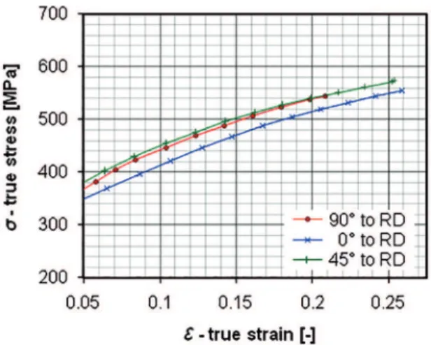
properties were determined by conducting uniaxial tensile pulling tests up to fracture on lat specimens (5 mm thickness, 6.5 mm width and 32 mm gauge length) along 0° (longitudinal), 45° (diagonal), and 90° (transverse) to the rolling direction (RD). These tests were carried out at ambient temperature (298°K) on 20kN Tensometer (Make –KIL, Model -PC 2000), at a strain rate, 2.5 x 10⁻⁴ s-1, according to Indian Standard
IS 1608:200516. Thus, true values of tensile properties
such as: yield strength (YS), tensile strength (UTS), uniform elongation (UEl.); total elongation (TEl.) were determined from load-extension curves. The strain
hardening exponent (n), an indicator of formability,
was evaluated by regression method, applying on true stress-strain low curves (shown in Figure 1).
The plastic strain ratios (r), known as conventional
formability indicators, were evaluated from tensile
tests at an elongation 16-17% of UEl and using Eq.1,
as per Indian Standard IS 11999:200717.
/
ln
/
/
ln
/
( )
r
=
f
Wf
t=
^
w w
0h
^
t t
0h
1
/
( )
r
m=
]
r
0+
2
r
45+
r
90g
4
2
/
( )
r
r
02
r
45r
902
3
D
=
]
-
+
g
Where, rm = normal plastic strain ratio, ∆r = planar plastic strain ratio, Ԑw and Ԑt = true strain along width and thickness respectively; w0 and t0 = specimen width and thickness before test respectively; w and t = specimen width and thickness after test respectively.
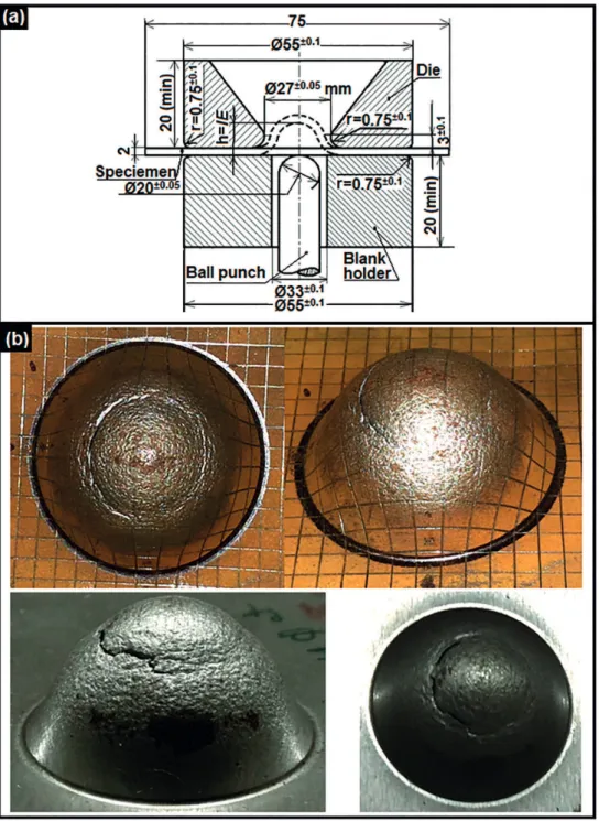
The biaxial strechability of the steel was determined by conducting Erichsen cup test (electro-hydraulic drive Erichsen make sheet metal testing machine, Model -140, drawing force 0-30 kN, sheet holding force 0-34 kN, assembled with tooling arrangements shown in Figure 2a) on 2 mm thick, 75 mm square specimens at ambient temperature, 298°K, according
to Indian standard IS 10175(Part 1): 199318. These
specimens were cut from 14 mm thick strips by using CNC Wire-cut EDM machine followed by grind inish,
Table 1: Chemical composition of the steel (in %wt.).
Elements C Mn Si S P Ni Cr Al Cu Sn As Sb Fe
Figure 1: True tensile stress-strain low curves along 0°, 45°, and
90° to RD.
wherein proper precautions were taken to maintain inherent material properties in an intact condition. After completion of the test, cup height (Figure 2b)
was measured and expressed as Erichsen Index (IE).
2.3. Cylindrical cup manufacturing
A series of cup drawing experiments were conducted by multistage (three stages) deep drawing with simultaneous ironing process on high speed mechanical press machines, without using
blank-holder considering relatively thicker blanks5. The
sequence of processing steps those were followed in the experimental work such as: blanking of strips to obtain circular lat blanks - facing of blanks at both sides - stress relief annealing, surface treatment and lubrication - stamping of blanks to obtain a preformed shape- stress relief annealing, surface treatment and lubrication - irst stage of cup drawing - stress relief annealing, surface treatment and lubrication - second stage of cup drawing - stress relief annealing, surface treatment and lubrication - third stage of cup drawing - stress relief annealing.
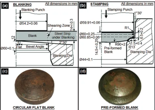
The circular steel blanks, 60 mm diameter, were cut from 14 mm thick heat treated strips by blanking operation on a 500 Ton high speed mechanical press, assembled with blanking tools, schematically shown in Figure 3a. Blanks thus produced (Figure 3c) were undergone surface machining (facing) at both sides up to 12 mm thick, in order to discard the decarburized surface layer generated during the heat treatment. These 12 mm thick, 60 mm diameter circular lat blanks were associated with a low diameter to thickness ratio, resulted to unsuitability for cup drawing directly from them. Hence by introducing an additional forming step, i.e. stamping operation, which was held on a 250 Ton mechanical press assembled with suitable die-punch
arrangements, schematically shown in Figure 3b, and thus lat shape of the circular blank was modiied to a little draw-in form (Figure 3b) with concave radius,
R13, called as preformed blanks (Figure 3d). Then by
using these blanks, long cylindrical cups were formed in three draw stages, consisted of deep drawing with simultaneous wall ironing processes. In irst draw stage, cups with smaller height were formed on a 500 Ton high speed mechanical press machine, assembled with a suitable die-punch set, shown in Figure 4a. Then in second and third draw stages, cup’s height was increased with a simultaneous decrease in its diameter and wall thickness. The second and the third stage cup drawing were performed on high speed mechanical press machines of 350 Ton and 250 Ton capacities respectively with suitable die-punch arrangements, schematically shown in Figures 4b-c, respectively. More importantly, all the process parameters which were followed in cup drawing experiments are illustrated in Table 2.
In order to remove strain hardening efect7, 19,
components after each forming step were subjected to a stress relief annealing treatment by heating at 923-933°K for 4 hours followed by furnace cooling up to 473°K and then air cooling to room temperature, 298°K. For achieving an efective lubrication during high speed cold forming processes as explained here,
as suggested by BlueScope Technical Bulletin20 and
Tschaetsch21, prior to each forming step (after stress
relief annealing cycle) components were undergone to a typical surface treatment consisted of acid pickling (HCl: 6-7%, PH: 2-5) to clean oxide coating; applying phosphate coating with 5-10 µm thick porous layer to ensure a good lubricant carrying ability during deformation processes; lubricating by immersing in soap solution (33% soap lakes) for approximately 2 hours to make sure of a complete difusion of the solution into pores of the phosphate coat layer.
3. Results and Discussion
3.1. Material properties
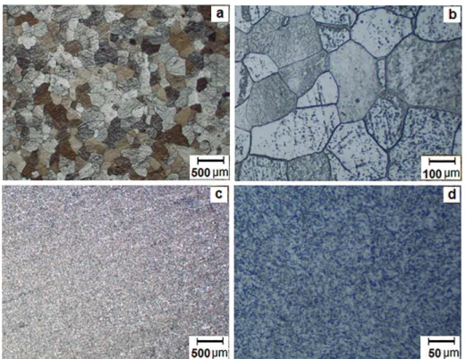
Figures 5a-bshow the typical micrographs (OM) of as-received hot rolled steel strips, which presented a microstructure, composed of pearlite-ferrite with an average grain size, ASTM No. 5-6. Figures 5c-d present the typical micrographs of the steel after heat treatment, which presented a microstructure composed of uniformly distributed globular cementite in a ferritic matrix. The average grain size was determined as ASTM No. 7-8. In this case, the hardening by water quenching is responsible for reinement of grains
Figure 2: a) Schematic showing of Erichsen cup test arrangements; b) photo images of Erichsen cup specimens.
by maintaining a balance between formability and orange peeling efect in cup drawing process. Also, the prolonged tempering cycle is found to contribute in globulization of cementite, which indicates the
enhancement of formability22 by ensuring dislocations
to move easily during metal deformation.
Table 3 summarizes the mechanical properties (mean values of anisotropic components) of the heat treated steel as the potential input material for cup manufacturing processes. It shows the surface hardness
as ~134 BHN. The tensile strength (UTS) ~561.4 MPa
with yield ratio 57.28% and total elongation (TEl)
~40.01% with uniform elongation (UEl) ~24.37%,
altogether indicate a good strength-ductility combination.
The high strain hardening exponent (n) -value 0.274,
signiies its uniform strain dispersibility as well as high strechability1, 3, 23. By showing the normal plastic strain
ratio (rm) -value, 1.18 (>1) with a low planar plastic anisotropy (∆r) -value, 0.17, the steel is found moderate
Figure 3: Schematically showing of arrangements, a) blanking operation, and c) stamping operation; Photo images, b) circular lat blank,
and d) preformed blank.
Figure 4: 3-stage cup drawing process, a-c) schematically showing of arrangements; d-f) photo images of drawn cups.
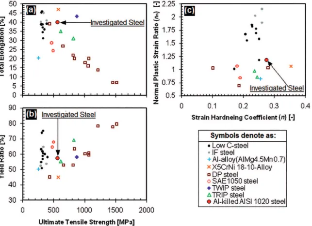
properties as well as formability parameters of the steel with that of conventional low carbon steels and AHSS (Advance High Strength Steels) obtained from various literatures, as shown in Figures 6a-c, the steel stands taller by strength than that of low carbon steels and also is found competitive than few AHSS, which are signiicant.
Erichsen cup test shows the Erichsen Index
(IE) -value, 12.71 (Table 3), which indicates a
high biaxial strechability of the steel attributed
to high n-value and elongation23, 25. Moreover, the
Table 2: Equipments, tools and process parameters of multistage drawing
(a) Equipments/ tools (b) Technical details/ process parameters
A Press machine
First draw stage: Capacity- 350 Tons, crank type mechanical press of single action, stroke length –
610 mm ram speed - 183 mm. s-1
Second draw and Third draw stages: Capacity- 250 Tons, crank type mechanical press of single
action, stroke length - 640 mm, ram speed - 192 mm. s-1.
B Draw die
Die Proile (irst - second - third draw stages): Schematically shown in Figures 4(a), (b) and (c)
respectively.
Surface inish- grind inished with polished surface at efective working zones. Die material- IS: T108/ JIS: SK 3, 4 steel
Die hardness- 578-652 BHN on hardened and tempered condition.
C Cupping punch
Punch proile(irst - second - third draw stages): Schematically shown Figures 4(a), (b) and (c)
respectively.
Surface inish- grind inished with polished surface at efective working zones. Punch material- IS: T108/ JIS: SK 3, 4 steel.
Punch hardness- 578-652 BHN on hardened and tempered condition.
D Stripper (three segmented type)
First draw stage- 31.8+0.06mm diameter (minimum). Second draw stage- 31.2+0.06mm diameter (minimum). Third draw stage- 30.5+0.06mm diameter (minimum).
(Stripers are itted at the exit end of draw dies, with peripheral spring tension for extraction of drawn cups after each stage of drawing).
E Die-punch clearance First draw stageSecond draw stage - 6.00+0.10mm. - 4.20+0.10mm. Third draw stage - 3.80+0.10 mm.
F Lubricant used Water diluted soap lakes [33% Sodium oleostearate, technical (soap noodles) as per IS 10513-1983, Table 1, clauses 4.4, 8.1 & 8.3, type-1 and 67% H
2O].
Figure 5: Typical micrographs (OM) of Al-killed AISI 1020 steel strips after, a-b) hot rolling, and c-d) heat treatment.
Table 3. Mechanical properties of the steel after heat treatment.
YS (MPa) UTS (MPa) UEl32 (%) TEL (%) n C (MPa) rm (17%) ∆r (17%) IE (mm) Hardness (BHN)
321.56 561.4 24.37 40.01 0.274 827.52 1.18 0.17 12.71 134
Figure 6: Comparisons of Al-killed AISI 1020 steel with conventional sheet metals (obtained from literatures) with respect to, (a) TEl.
vs. UTS; (b) YR vs. UTS; (c) rm vs. n –value.
3.2. Effects of multistage cup drawing
Figures 4d-f show the photo images cups drawn in irst, second and third draw stages respectively, wherein it is distinguished that cup length increases on the advancement of draw steps. These igures also portray the average dimensions of cups drawn in the respective step, wherein the inal draw stage has shown a cup size, ~56mm length, ~36.85 mm diameter and ~3.8 mm wall thickness, which are signiicant. It is also seen that cups have been manufactured with free from common forming defects, like: wrinkling, earring, edge tearing, localized thinning and preferential thickening etc.
Moreover, good surfaces inish, i.e. free from galling,
welding, scratch marks, score marks and orange peeling efects, is being witnessed on the cup walls. Also, few other important efects of cup drawing processes, such as: wall thickness distribution proiles, Drawability and Ironability parameters, punch force history, and strain distribution proiles are evaluated for each draw step and are discussed in the following sub sections.
3.2.1. Wall thickness distribution proiles
The dimensions of drawn cups were measured (shown in Figures 4d-f) by digital micrometers after sectioning the cups at middle by a diamond saw. Thus, cup wall thickness of each draw stage
was obtained at diferent zones, i.e. from base to top
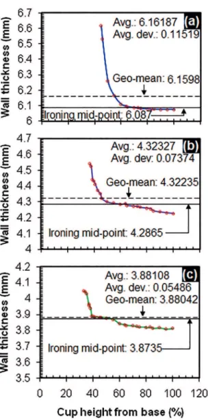
mouth edge and then the thickness distributions were graphically plotted with respect to the cup height, as shown in Figures 7a-c. These igures indicate thickness variation in term of a divergence of ironing mid-point from the respective geometrical mean of measured dimensions. Thus, degrees of deviation are observed as 0.0728 mm (+), 0.03585 mm (+) and 0.00692 mm (+) in irst – second - third draw steps respectively. These trends conirm to the increasing dimensional control on advancement of the draw steps, manifested by increasing predominance of
wall ironing in the forming processes, agreed by8-11.
At the same time, it is also observed that the initial blank thickness remains almost unchanged under a region of lat bottom face of the draw punch in all
Figure 7: Graphical showing of cup wall thickness distribution,
(a) 1st draw, (b) 2nd draw and (c) 3rd draw.
3.2.2. Drawability and ironability parameters The drawability and the Ironability parameters of draw stages were evaluated by using following standard formulae, obtained from diferent literatures21, 26, 27.
Draw ratio
/ ( )
D Di P i 4
b =
-^ h
Overall or maximum draw ratio (β0), i.e. limiting draw ratio
/ ( )
LDR =D D0 p f- 5 ] g
Draw reduction
% / x1 ( )
rd = Di-1-Dp i- Di-1 00 6
]
g
6
^ h@
Overall or maximum draw reduction
% / x ( )
rd-0 = D0-DP f- D0 100 7
]
g
6]
g
@ Ironing ratio/ ( )
IR =Ti-1 Ti 8
] g
Overall or maximum ironing ratio (IRo), i.e. limit ironing ratio / ( )
LIR =T T0 f 9
] g
Ironing reduction
%
/
x
( )
r
i=
T
i-1-
T
iT
i-1100
10
]
g
6
]
g
@
Overall or maximum ironing reduction
%
/
x
1
( )
r
i-0=
T
0-
T
fT
000
11
]
g
6
]
g
@
Principal strain
% ln D d / D d x100 ( )12 p i 12 i 12 i2 i2
{ = - - -
-^ h
6
]
g
]
g
@
Reduction of area
%
/
x
1
( )
r
a=
A
i-1-
A
iA
i-100
13
]
g
6
]
g
@
Overall reduction of area
%
/
x
1
( )
r
a-0=
A
0-
A
fA
000
14
]
g
6
]
g
@
Drawing eiciency
%
ln
x 00
1
( )
15
d
h
=
b
^ h ^ h
Overall drawing eiciency
%
ln
LDR
x
1
00
( )
16
d 0h
-=
^ h
]
g
Ironing eiciency in each step
% 0 703125. x rin% /100 ( )17
i a
h =
^ h
6
]
g
@
Overall ironing eiciency
[ .0 703125x r in% /100] ( )18
i 0 a 0
h- =
-^ h
]
g
Where, D0 = diameter of the blank (before cupping); Di, Di-1 = outer diameter of the cup after and before the stage-(i) respectively; Dp-i, Dp-f = diameter of punch in the stage-(i) and the inal stage respectively; T0 = thickness of the blank (before cupping); Ti, Ti-1 and Tf = thickness of cup wall in the stage-(i), (i-1), and the inal stage respectively; di, di-1 = inner diameter of cup after and before the stage-(i) respectively; and A0, Ai, Ai-1, Af = cross section area of cup before the irst draw stage, after the stage-(i), after the stage-(i-1) and after the inal stage respectively.
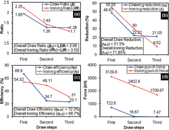
Figure 8a graphically presents the stage wise variation of cup drawing ratios, i.e. ‘β’ and ‘IR’, with showing their maximum values in first draw stage and then decrease in subsequent steps gradually.
Figure 8b shows the reduction parameters, i.e. ‘rd’
and ‘ri’, demonstrate a similar trend as of ratios.
The reduction in draw reduction % is attributed by increased draw strains, associated with advancement of draw steps, an expected phenomenon explained
bySuchy7. Also according to him, there is a
Figure 8: Stage wise graphical showing, a) Draw and Ironing Ratios, b) Draw and Ironing reductions, c) forming eiciencies, and d)
punch forces.
The values of critical parameters such as: LDR,
overall draw reduction (rd-o), LIR and overall ironing
reduction (ri-o) were evaluated for the overall draw
steps, as: 2.06, 51.5%, 3.55 and 71.85% respectively. A
comparison with literatures shows that both LDR and
rd-o are lower than LDR value 2.2, reported by Tajally et al.28 and r
d-o value 70.7%, revealed by Jawad
26. But
at the same time, LIR and ri-o are found higher than that of values 2.5-3.3 and 60-70%, shown by Shi and Gerdeen27 respectively. These values imply that the steel
can successfully be drawn with moderate drawability under high ironability conditions.
Figure 8c represents a stage wise variation of forming eiciencies, persuaded by deep drawing and ironing processes. Herein also, the forming eiciencies exhibit a decreasing trend, which might be due to increasing strain factor as well as of increasing strained % of cup
height occurred in subsequent steps7. The igure also
indicates a predominance of draw deformation in irst step and then of wall ironing in further two steps. More signiicantly, the overall draw and ironing eiciencies were estimated as 72.3% and 68.7% respectively.
3.2.3. Punch force history
The punch forces such as: forces caused by drawing and ironing actions of punches in three draw steps were determined by following equations obtained from various literatures. In these equations a plain strain condition was assumed, because of circumference of the cup wall was constrained by the rigid punch from shrinkage and thus it yielded a negligible (≈0) circumferential strain.
Considering a non steady state of plastic deformation in the irst draw stage, the draw punch force was
calculated by Eq.19, described byBoljanovic29.
. / /
/ / ( )
ln exp
exp
P D t k D D
H D D B
1 1 2
2 2 19
D p P
P
f m
1 0
0
$ $ $
$ $
r n r
n n r
= +
+
-
-^ -^ ^
^
^ ^
hh h
h
h h
6" 6" , @ ,5 ? @
Where, Dp = Punch diameter, D0 = Blank diameter, t = wall thickness, kf-m = Average low stress (MPa), μ = Coeicient of friction at die radius and was assumed a value, ~0.1629, H = Blank hold down force, B = Force
Since in the present investigation, no blank-holder was used, the Eq.19 was modiied to Eq.20 by excluding
the blank hold down force (H):
/ / ( )
ln exp
P D t k
D D B
1 1
2 20
D
p f m
P 1 0 $ $ $ $ $ r n r = + -^ ] ^ h g h
>* 4 H 5 ?
The average low stress was calculated by using the Eq.221:
/
( )
k
f m-=
]
k
f-0+
k
f-1g
2
21
Where, kf-0 = low stress before forming (forφp= 0) i.e. yield stress of the material, kf-1 = low stress at the end of forming (forφp = φmax) and value of this
stress was evaluated by using the equation of low stress curve, kf = Cφn 21.
The bend force was calculated by using the Eq. 2230:
/ . tan / ( )
B=6
]
kf m- $L t$ 2g
2]
Rd+0 5tg
@$ ^c 2h 22Where, L = total length to bend i.e. the perimeter (πD0) of the preformed blank (189.12 mm), t = thickness
of the preformed blank (13 mm), Rd = bend radius i.e.
die radius (R12), γ = bend angle i.e. 90° in the present investigation.
In second and third draw steps plastic deformation was considered as of steady state process, wherein deformation zone did not change (only diameter changed). The draw punch forces in these steps were
evaluated by Eq.2329.
. / . / .
/ / ( )
tan
x x x
x
P D k
D D
1 1 1 2 180 1 21 1 44
1 2 1 ( /tan 23
i
f m
m i m i
P t
1 2
i i
r nr a
a n
= +
+ - n a
-- -^ ^ ^ ^ ] h h h h g
6 @ >" " , ", " ,,H
Where, i =draw stage no., Pi =punch force in i
-stage, Dp-I = Punch diameter in i-stage, ti =cup wall
thickness in i-stage after drawing, Dm-i =mean dia.
of cup after drawing in i-stage, Dm(i-1) = mean dia. of cup after drawing in (i-1)-stage, α = semi die angle in
degree, kf-m = average low stress in MPa (calculated
by Eq.19, assuming kf-0 = yield stress of the material because of stress relieving treatment after drawing),
μ = interface friction coeicient and was assumed to
be ~0.1629.
The ironing punch force in each draw step was
evaluated by using Eq.24, stated by Folle et al.31.
/ / ( )
F=kf m- Ai{P
6
1+n a+2a 3{p@
24Where, kf-m = mean low stress in MPa (Eq.19), Ai = cross-sectional area of the cup after ironing in i-stage,
φP = principal strain, α = semi die angle in degree, μ
= interface friction coeicient and was assumed to be ~0.1629.
Figure 8d depicts the punch forces (both draw and ironing forces) with their stage wise variations. It shows downward trends, which has been obtained
for both types of forces while moving from one draw step to another. Further, it is distinguished that the ironing force is found to be quite higher than that of the corresponding draw force in each draw stage, which conirms a signiicance of the ironing in deformation processes.
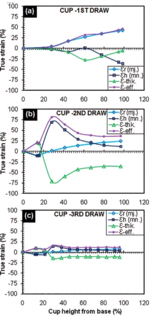
3.2.4. Strain distribution proiles
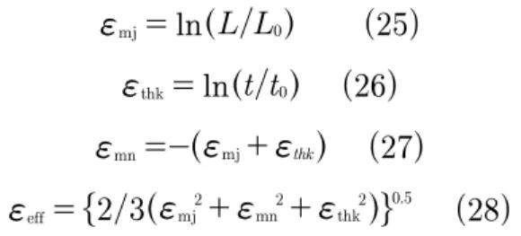
The major (hoop), minor (radial), thickness and efective strains on outer surface of the cup in each draw step were evaluated by following standard equations and results were plotted to a graph with respect to the cup height, known as strain distribution proile. The major (Ԑmj.) and the thickness (Ԑthk.) strains were estimated
by Eqs.25 and 26 respectively26, considering changes
in dimensions before and after drawing of cups. The minor strain (Ԑmn.) and the efective strain (Ԑef.) were calculated by using volume constancy formula, Eq.27,
and slab method, Eq.28, respectively26.
/
( )
ln
L L
25
mj 0
f
=
^
h
/
( )
ln
t t
26
thk 0
f
=
^ h
( )
27
mn mj thk
f
=-
^
f
+
f
h
/
( )
2 3
.28
eff mj2 mn2 thk2
0 5
f
=
"
^
f
+
f
+
f
h
,
Where, L0 = height of a point considered for the
measurement, on component before drawing, L =
height of the point on component, after drawing, t0 =
thickness of a point considered for the measurement,
on component before drawing and t = thickness of the
point on component, after drawing.
Figures 9a-c demonstrates strain distribution proiles of outer surfaces of cups in irst, second, and third draw stages respectively. The distribution of inner surface strains, which have almost a same shape and magnitude as of the outer one, is not shown here for the simplicity of data presentation. The igures are self explanatory, showing trends and natures (tensile or compressive) of strains (Ԑmj., Ԑthk., Ԑmn., and Ԑef.). Herein, strain curves suggest that the weaker zone of a cup (in a particular stage) exists at its shoulder portion, which is indicated by peaks of the minor and the thickness strains at this zone.
4. Conclusions
The conclusions of this paper can be summarized as follows:
• Water quenched and tempered (953°K for 30
Figure 9: Stage wise graphical showing of strain distribution proiles
of cups, a) 1st draw, b) 2nd draw, and b) 3rd draw.
ferritic matrix and having an average grain size ASTM No. 7-8.This as a whole entailed a good combination of strength-ductility-formability, which indicated that the steel could ind cup drawing applications with moderate drawability and maximum strength up to ~561 MPa.
• Unlike conventional sheet metal works, thicker
blanks (12 mm thick, 60 mm diameter circular blanks) were drawn into cylindrical cups of length ~56 mm, diameter ~36.85 mm and wall thickness ~3.8 mm, by using a modiied processing route consisted of pre-forming of blanks and three stage deep drawing with simultaneous ironing without using blank-holders.
• The drawability and ironability parameters of
overall draw stages were evaluated as: overall
draw reduction 51.5 %, LDR 2.06, overall
ironing reduction 71.85%, and LIR 3.86,
which indicated the actual press formability of the steel.
• The wall thickness distribution, punch force
history, and strain distribution proiles of cups, were also obtained and shown for further improvement of the process and the tools used in.
5. Acknowledgements
The steel and experimental facilities were extended by the senior general manager of Metal & Steel Factory, Ishapore, West Bengal, India. The authors gratefully acknowledge this.
6. References
1. Hosford WF, Caddell RM. Metal forming - mechanics and metallurgy. 3rd ed. Cambridge: Cambridge University Press; 2007.
2. BlueScope Steel. Press-Forming Steel Sheet and Strip. BlueScope Steel Technical Bulletin TB-F7. Rev 2; 2003. Available from:
<http://www.steel.com.au/~/media/Files/ Build% 20and%20 Construction%20Technical%20Library/Technical%20 Bulletin/200612_TB-F7.ashx.>. Access in: 30/06/2016. 3. Ravi Kumar D. Formability analysis of extra-deep drawing steel.
Journal of Materials Processing Technology.
2002;130-131:31-41. http://dx.doi.org/10.1016/S0924 0136(02) 00789-6. 4. Marumo Y, Saiki H, Ruan L. Efect of sheet thickness on deep
drawing of metal foils. Journal of Achievements in Materials and Manufacturing Engineering. 2007;20(1-2):479-482.
5. Saleh AH, Ali AK. Development technique for deep drawing without blank holder to produce circular cup of brass alloy. International Journal of Engineering & Technology. 2015;4(1):187-195.
http://dx.doi.org/10.14419/ijet.v4i1.3516.
6. Oluwole OO, Anyaeche CO, Faola OV. Efect of draw ratio and sheet thickness on earing and drawability of Al 1200 cups. Journal of Minerals & Materials Characterization & Engineering. 2010;9(5):461-470. http://dx.doi.org/10.4236/
jmmce.2010.95032.
7. Suchy I. Handbook of Die Design, 2nd ed. New York:
McGraw-Hill; 2006.
8. Choi JM, Kim JH. Dimensional accuracy of cylindrical cups in multi-stage drawing of Aluminum sheet metal. Transactions of Materials Processing. 2015;24(2):115-120. http://dx.doi.
org/10.5228/KSTP.2015.24.2.115.
9. Barros PD, Alves JL, Oliveira MC, Menezes LF. Earing evolution during drawing and ironing processes. Blucher Mechanical Engineering Proceedings. 2014;1(1):3954-3973. http://dx.doi.
org/10.5151/meceng-wccm2012-19645.
10. Aleksandrovic S, Dordevic M, Stefanovic M, Lazic V, Adamovic D, Arsic D. Diferent ways of friction coeicient determination in stripe ironing test. Tribology in Industry. 2014;36(3):293-299.
11. Moshksar MM, Kalvarzi AH. Ironing of Aluminum cups.
Materials and Manufacturing Processes. 2007;16(4):461-470.
12. Ramirez FJ, Domingo R, Packianather MS, Sebastian MA. Enhancing multistage deep-drawing and ironing manufacturing processes of axisymmetric components: analysis and experimentation.
International Journal of Manufacturing Engineering.
2014;2014(596128). http://dx.doi.org/10.1155/2014/596128. 13. Danckert J. The residual stress distribution in the wall of a
deep-drawn and ironed cup determined experimentally and by FEM.
CIRP Annals - Manufacturing Technology. 1994;43(1):249-252.
http://dx.doi.org/10.1016/S0007-8506(07)62206-9.
14. Indian Standard-IS. IS 4748:1988: Methods of Estimating Average Grain Size of Metals. 1st revision. New Delhi: Bureau
of Indian Standards; 1989.
15. Indian Standard-IS. IS 1500:2005: Method for Brinell Hardness Test for Metallic Materials. 3rd revision. New Delhi: Bureau
of Indian Standards; 2005.
16. Indian Standard-IS. IS 1608:2005: Metallic Materials – Tensile Testing at Ambient Temperature. 3rd revision. New Delhi:
Bureau of Indian Standards; 2005.
17. Indian Standard-IS. IS 11999:2007: Method for Determination of Plastic Strain Ratio ‘r’ for Sheet Metals. 1st revision. New
Delhi: Bureau of Indian Standards; 2007.
18. Indian Standard-IS. IS 10175 (Part 1):1993: Mechanical Testing
of Metals - Modiied Erichsen Cupping Test - Sheet and Strip.
1st revision. New Delhi: Bureau of Indian Standards; 1993. 19. Shah K, Bhatt D, Panchal T, Panchal D, Dogra B. Inluence
of the process parameters in deep drawing. International Journal of Emerging Research in Management & Technology.
2014;3(11):16-22.
20. BlueScope Steel. Lubrication of Steel Sheet and Strip for Forming. BlueScope Steel Technical Bulletin. TB-F1 Rev 2;
2003. Available from: <http://steelproducts.bluescopesteel. com.au/iles/TB-F1.pdf.>. Access in: 30/06/2016.
21. Tschätsch H. Metal Forming Practise (Processes-Machines- Tools). Translated by Koth A. New York: Springer-Verlag; 2006.
22. Banerjee K. Physical Metallurgy and Drawability of Extra Deep Drawing and Interstitial Free Steels, Recrystallization. In: Krzysztof Sztwiertnia, ed. Recrystallization. Rijeka: InTech
Europe; 2012.
23. Sunil SU, Pai KB. Investigation of formability of CRCA steel sheet by Erichsen Cupping Test analysis. IOSRJournal of Mechanical and Civil Engineering. 2014;11(2/1):52-55. http://
dx.doi.org/10.9790/1684-11215255.
24. Reddy ACS, Rajesham S, Reddy PR, Ramulu J, Kumar A. Experimental study on strain variation and thickness distribution in deep drawing of axisymmetric components. International Journal of Current Engineering and Technology. 2014;Spl.
Issue-2:178-182.
25. Kimura T. Formability of TRIP type banitic ferrite steel sheet.
Kobelco Technology Review. 2011;30:85-89.
26. Jawad WK. Design modiication in a multi-stage deep drawing process. Iraqi Academic Scientiic Journal–Engineering &
Technology Journal. 2008;26(1):29-44.
27. Shi MF, Gerdeen JC. A theoretical study of the ironing process in sheet metal forming. Journal of Materials Shaping Technology.
1989;7(4):203-211. http://dx.doi.org/10.1007/BF02834772. 28. Tajally M, Emaddodin E, Qods F. An Experimental Study on
Earing and Planar Anisotropy of Low Carbon Steel Sheets.
World Applied Science Journal. 2011;15(1):1-4.
29. Boljanovic V. Metal Shaping Processes: Casting and Molding; Particulate Processing; Deformation Processes; Metal Removal.
New York: Industrial Press; 2010. 428p.
30. Dieter GE. Mechanical metallurgy. 3rd ed. London: Mc
Graw-Hill; 1988.
31. Folle LF, Silveira Netto SE, Schaefer L. Analysis of the manufacturing process of beverage cans using aluminum alloy.
Journal of Materials Processing Technology.