Evaluation of Corrosion Caused by the use of
In Natura
Biogas in Steam Generator Boilers
of Carbon Steel Structural Elements
Marcellus Fontenellea,b, Helton José Alvesa,c*, Marcos Roberto Monteirod, Silvia Midori Higae,Carlos
Alberto Della Roveref, Eder Luis Pellizzerb, Isaddora Fontenelleg
Received: June 12, 2016; Revised: January 23, 2017; Accepted: March 11, 2017
This work evaluates the corrosion process caused by the presence of hydrogen sulide in the biogas in natura, in steels commonly used in the construction of steam generator boilers, simulating conditions close to those found on the real application of these materials, exposing the test bodies directly to biogas
in natura, lame of combustion and gases resulting from the combustion of this biofuel, in chimney. After 314 hours of exposure under the speciied conditions, the corroded surfaces of ASTM A178 and ASTM A516 were analyzed, by optical microscopy, electronic scanning microscopy, X-ray difraction and surface hardness. The determination of corrosion rates for each test condition and each material tested can be used as a parameter for the determination of the minimum tolerance for mechanical stability, in the calculation of the minimum required thickness of the structural elements of the steam generator boilers fed to biogas.
Keywords: biogas; combustion; corrosion; steam generator; hydrogen sulide.
* e-mail: [email protected]
1. Introduction
Biogas has in its composition, in addition to methane (CH4 – 55-70%), carbon dioxide (CO2 – 30 to 45%) and hydrogen sulide (H2S – 500 to 4000 ppm), in addition to other minor components according to Schafer et al.1. Combustion is an oxidation process
where the elements carbon and hydrogen of the fuel will form CO2 and H2O, which in a compound fuel such as biogas occurs separately for each of its constituents. Thus, methane oxidizes with air oxygen, forming carbon dioxide and water vapor, but the hydrogen sulide in its oxidation process will form sulfur trioxide (sulite) and water vapor in the reaction of equation 1:
The use of biomass as fuel in steam generator boilers is defended by Demirbas3 as an alternative to be considered
in replacement to fossil fuels. Saidur et al.4 point out the
agricultural waste as a viable and cost-efective option for use as fuel in steam generator boilers, however the viability of the use of biogas in natura, for this application requires a comprehensive and conclusive study, in relation to real inluence on the process of corrosion and weakening of structural elements of carbon steel, due to the presence of hydrogen sulide, which will accelerate the corrosion process of the structural elements of these boilers, reducing its useful life, since, according to Chiaverini et al.5, the element iron,
present in steel, will gradually switch to iron oxide III (Fe2O3), no longer being part of the steel structure, with consequent reduction of its mass. According to Moreira6, the simplest
representation of a process of a steel corrosion in an acidic environment is given by equation 2:
a Postgraduation Program in Engineering of Energy in Agriculture – PPGEA, Western Paraná State University – UNIOESTE, R. Universitária, 2069, 85819-130 Cascavel, PR, Brazil
b University of Western Santa Catarina - UNOESC-Campus de Xanxerê, R. Dirceu Giordani, 696, Jardim Tarumã, 89820-000 Xanxerê, SC, Brazil
c Laboratory of Catalysis and Biofuel Production – LabCatProBio, Federal University of Paraná - UFPR-Setor Palotina, R. Pioneiro, 2153, Jardim Dallas, 85950-000 Palotina, PR, Brazil d Department of Mechanical Engineering – DEMec, Federal University of São Carlos – UFSCar,
Rod. Washington Luiz, km 235, 13560-971 São Carlos, SP, Brazil
e Academic Department of Materials Engineering – DAEMA, Federal University Technology of Paraná – UTFPR, Av. dos Pioneiros, 3131, 86036-370 Londrina, PR, Brazil
f Department of Materials Engineering – DEMa, Federal University of São Carlos – UFSCar, Rod. Washington Luiz, km 235, 13560-971 São Carlos, SP, Brazil
g Postgraduation Program in Mechanical Engineering – PosMec, Federal University of Santa Catarina - UFSC Campus Universitário, Trindade, 88040-900 Florianópolis, SC, Brazil
( )
H S
O
H O
SO
2
2+
4
22
2+
2
31
In the presence of moisture, the sulite will be diluted by the water vapor present in the combustion gases, forming sulfuric acid (H2SO4). These conditions are commonly observed in the output ducts of the combustion gases from
various types of equipment, such as steam generator boilers 2.
( )
Fe
nH
Fe
nn
2
H
2
2
MacDonald et al.7 developed a study to evaluate the carbon
steel corrosion in cyclic exposures to aqueous elemental sulfur. For this study, was used a “corrosion cell”, composed of a chamber where carbon steel samples were in contact with 320 g of sulfur and 170 g of distilled water, forming an aqueous elemental sulfur, in cycles of 4 days and at room temperature, followed by 6 days of exposure to the atmosphere. The study established a corrosion rate, in meters per year, regarding the number of cycles, based on the weight loss of the test bodies. Hansen et al.8 used a system to evaluate the corrosion caused by deposition, in which the test bodies were exposed to the gases from the combustion of wheat straw biomass, in the interior of the furnace of a steam generator boiler for 7 hours, creating conditions closer to those found in real conditions than the situation proposed in the experiment by MacDonald
et al.7, Michelsen et al.9 and Frandsen et al.10 have applied
the same methodology adopted by Hansen et al.8, in other experiments, for evaluation of corrosion on metals exposed to corrosive environment in furnaces of steam generator boilers. The corrosion evaluation experiments in steel should be performed in several cycles of short duration, because studies conducted by Yilbas et al.11 report that several
cycles of heating and cooling, even with small amplitude of temperature variation amplify the efect of corrosion, causing damages, even supericial, in lowcarbon content steels12.
One of the regulation codes most frequently used in the design and manufacture of steam generator boilers13, establishes
that for the determination of thickness of the walls under the efect of internal pressure, must be considered a coeicient “C” as a minimum tolerance for mechanical stability. The same code establishes that over this factor must be considered an over-thickness to prevent the efects of erosion or corrosion, however, in the literature consulted were found no studies on the type of materials or procedures for dimensioning to be employed in the design phase of steam generator boilers for applications where heat is obtained from the combustion of biogas in natura.
The objective of this work is to evaluate the efects caused by exposure of the structural elements of carbon steel, employed in the construction of steam generator boilers, to the hydrogen sulide, present in biogas in natura, determining the rate of corrosion and the behavior of diferent steel alloys employed in the construction of these boilers. For this, the steel alloys studied were exposed to diferent corrosive environments present in the stages of the combustion process, in conditions similar to those employed by Hansen et al.8, Michelsen et al.9, Fredsen10 and Jenkins et al.14,
generating data to subsidize the material speciication for the use of biogas in natura as fuel in steam generator boilers.
2. Materials and Methods
2.1 Selection and preparation of materials
The survey was conducted through the evaluation of the damage caused by corrosion, in the following commercial
materials, normally employed in the construction of steam generator boilers:
ASTM A178 Degree C – Carbon steel to manganese, in the form of electric resistance welded pipes, with a maximum composition 0.35% C and maximum 0.80% Mn. Structure predominantly with α ferrite and the presence of γ austenite. Frandsen10 speciies this material to be employed in the tube
bundle tubes of boilers;
ASTM A516 Degree 65 - Carbon steel in the form of lat sheets, with maximum composition: 0.26% C; 0.79 to 1.3% Mn and 0.13 to 0.45% Si. Structure predominantly with ferrite α and presence of γ austenite. ASME15 speciies
this material to be employed in the tube sheets and drum of the boilers.
The test bodies were extracted from raw tubes and sheets, cut on coin shape, with 20mm diameter. Were sanded for removal of residues and oxides resulting from the manufacturing and cutting process, with 60, 80, 120 and 180 240, 320, 400 and 600 sandpaper. After the surface preparation the test bodies were identiied and weighed in analytical balance, with scale division of 0.1 mg. The test bodies were produced, prepared and assayed in duplicate. Were also prepared the reference test bodies of each material, for comparison, in the characterization tests.
2.2 Testing performance place
The method applied in this experiment is based on the methodology employed by Michelsen et al.9 and seeks to
approximate the conditions of the tests to the actual situation in the application of steam generator boilers using biogas in natura, resulting from the anaerobic biodigestion of swine and cattle manure.
The selected materials were exposed to temperature and pressure conditions similar to those present in a low-pressure steam generator boiler, fueled by biogas resulting from the anaerobic biodigestion of swine and cattle manure, in an equipment composed of burner, furnace and chimney. To perform the experiment it was used the equipment for grain drying air heating, existing in the Ajuricaba condominium, in the city of Marechal Cândido Rondon - PR, which has conditions similar to the biogas combustion process in a boiler, since it has:
i - Feeding system before the burner, where the biogas in natura
circulates, at room temperature; ii - Combustion environment, similar to a furnace, where the ambient temperature may reach 800 oC; iii - Exit ducts of gases, combustion products, where
the temperature of these gases can reach up to 180 oC and iv –
Availability of biogas supply in natura.
This equipment has been provided for the experiments, by the PTI Foundation and CIBiogás - ER (International Centre for Renewable Energy)16, with the necessary supply of
Figure 1 shows the equipment layout with an indication of places where were installed the test bodies to perform the experiment, namely: 1) Biogas feeding duct, before combustion, in contact with biogas in natura; 2) In the biogas combustion environment, within the furnace; and 3) Inside the exit chimney for the external environment, in contact with the gases resulting from biogas combustion.
on a AISI 316 stainless steel structure, inserted from the top of the chimney, by a steel cable system and installed on the base region of the chimney.
2.2.2 Parameters evaluated
During the exposure times of the test bodies to hydrogen sulide, the following parameters were registered:
- Temperature of test bodies exposed directly to the lame; - Temperature of the combustion gases in the chimney; - Concentration of H2S, CO2, O2, and H2 present in biogas
in natura, with biogas.
The control parameter for obtaining the data is the exposure time of the test bodies to speciied conditions.
The test bodies were divided into three groups with diferent exposure times:
Time 1: 74 hours of exposure; Time 2: 132 hours of exposure and Time 3: 314 hours of exposure.
After each exposure time, the test bodies were removed and cleaned for the removal of corrosion products from the surface, employing the methods described by ASTM17, and the
chemical cleaning procedure for removal of corrosion products is detailed in item 3.5 of the A1.1 table that standard. This method was chosen because it is the appropriate procedure for steels and the availability and safe use of the reagents (hydrochloric acid and hexamethylene). After cleaning were subjected to the tests and evaluations of:
2.2.3 Mass loss
Mass measurement of each test body in analytical balance with 0.1 mg scale division, before and after the exposure period to the conditions, for determining the loss percentage In order to eliminate the distortion in the mass loss values, caused by the diferences between the dimensions of the material used for the production of the test bodies of each
Figure 1: Air heater layout and positioning of the test bodies.
2.2.1 Mounting of the test bodies
Position 1: In the biogas feeding duct, where the test bodies were mounted in a corrosion chamber, built in PTFE (telon®), according to Figure 2, mounted in point 1 of Figure 1, in series with the duct biogas feeding, before the set of electrically-operated valves that control the functioning of the biogas burner of the heater.
Position 2: In the interior of the furnace, on the burner lame, where the test bodies were mounted on a AISI 316 stainless steel structure, in a height of 250 mm above the burner in the inal region of the reducing lame, where initiates the oxidizing region of the lame.
Position 3: In the interior of the chimney in contact with the combustion gases, where the test bodies were mounted
material tested, the mass loss calculations were divided into 2 groups:
a) Mass loss relative to the initial mass, calculated by equation 3:
.
( )
M
M
M
M
100
3
i
i f
D
=
Q
-
V
Where:
ΔM = Mass loss (%) Mi = Initial Mass (g) Mf = Final Mass (g)
b) Corrosion rate, calculated according standard17, by
equation (4):
/
( )
M
t
A T D
K W
4
$
$
$
D
D
=
Where:
ΔM/t = Corrosion rate (mm/year)
K = Dimensionless constant, to be used according to the scaling (K = 8,76 x 10⁶ for corrosion rate in mm/year)
W = Mass loss (g)
A = Area of the test body (cm2)
T = Exposure time (h)
D = Material density (g/cm3) (D = 7,86 g/cm3 for carbon
steels)
2.2.4 Surface hardness
The test bodies were submitted to the surface hardness test, Rockwell B (with sphere of 1.59 mm and load of 100 kgf), Held in Pantec analogic bench durometer, according ASTM18, which was more appropriate, since due to corrosion, the surfaces of the test bodies are not suitable to the Brinell or Vickers hardness tests, and also because they are low carbon steel, without tempering heat treatment.
2.3 Characterization
a) X-ray difraction, for determination of the crystalline phases present in the corroded surface of the materials, before and after exposure, performed on a Siemens Kristallolex equipment, in the range of 4o < 2θ < 40o, with Kα radiation
of copper (λ =1,54056 nm, 40 kV, 40 mA), nickel ilter and speed of 0,5o/min.
b) Optical microscopy (OM) of the cross section of the test bodies, to identify the type of granular formation of the phases present in the material before and after being attacked in diferent situations, identifying possible changes in the crystalline structure. The test bodies were cut, polished and attacked with Nital reagent at 2% in volume, with magniications of 100x, 200x and 500x, held in Leitz Labor Lux 12 ME S Microscope, equipped with Zeiss AxioCam ERc 5S camera.
c) Optical Microscopy (OM) of the corroded surface to identify the type of damage caused to the surface, with magniications of 50x, 100x, 200x and 500x, held in Leitz Labor Lux 12 ME S Microscope, equipped with Zeiss AxioCam ERc 5S camera.
d) Scanning Electronic Microscopy (SEM) to evaluate the damage caused on the attacked surface and the cross section and identify the chemical elements present on the surface, held in a scanning electron microscope, FEI Quanta 440, with energy dispersive spectroscopy system (EDS) attached.
3. Results and Discussion
In the exposure times of 74 h, 132 h and 314 h, were conducted 9, 34 and 45 cycles of heating and cooling of the test bodies, respectively. The diference between the average times of each cycle results from the greater or lesser availability of biogas in suicient amounts in the equipment used for the experiment.
The temperature of the test bodies exposed to the lame, in the furnace was: minimum of 470 ºC and a maximum of 550 ºC.
The temperature of the gases products of combustion, in the chimney was: minimum of 87 ºC and a maximum of 170 ºC.
During the experimental period, the averages of the levels of the constituents present in the biogas used in the experiment were: CH4 - 63,80%; CO2 - 34,87%; O2 - 0,91%; H2S - 2300 ppm and H2 - 1749 ppm, recorded by Dräger X-AM 7000 gas analyzer.
3.1 Mass loss
3.1.1 Mass loss in relation to the initial mass
Figure 3 indicates the averages of mass loss in relation to the initial mass of the test bodies, along with conidence intervals of about one standard deviation for each material. A direct evaluation of Figure 3 indicates that the steel ASTM A178 has greater weight loss when exposed to direct contact with biogas in natura, when compared to steel ASTM A516.
Another aspect that can be observed is the fact that both the analyzed materials present stability between the second and third testing time, indicating that the formation of a supericial layer after initiation of corrosion, it acts as a protective layer, preventing the spread of the corrosion process.
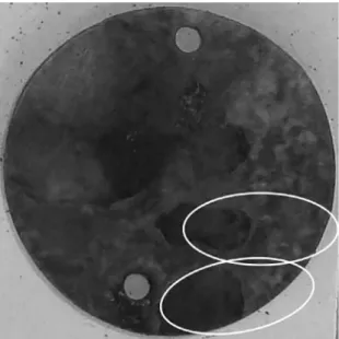
Figure 3 also shows a larger mass loss for the second time interval of exposure to combustion lame, compared to the third interval, which corresponds to a longer exposure time. These test bodies have sufered an accelerated process of mass loss, characterized by the supericial peeling, observable to the naked eye, according to Figure 4, which shows the surface of a test body that has been in direct contact with the combustion lame.
And it is evident that the mass losses are most signiicant when the material is exposed directly to the combustion lame of the biogas and that in the chimney, where the material is exposed to gases from the combustion along with air humidity and water vapor from the combustion. The corrosion process causes a mass loss equivalent to that observed in the test bodies exposed directly to the lame.
3.1.2 Corrosion rate
The most appropriate way of interpreting the corrosion process is by the corrosion rate, which must be calculated according to ASTM17. This parameter shows whether the
corrosion process is stable (with a constant corrosion rate), more aggressive (with a higher corrosion rate) or softer with (reduction in the corrosion rate). A process that has a corrosion rate equal to or near zero indicates that the corrosion process is inactive.
Figure 5 shows the corrosion rates calculated for each material exposed to biogas in natura, in each time interval, along with the conidence interval of about one standard deviation.
Figure 3: Mass loss percentage in relation to the initial mass.
Figure 4: Surface with peeling of the layer attacked by corrosion, in test body exposed directly to the combustion lame of biogas.
observed in the test bodies that were exposed directly to the combustion lame of the biogas.
As the mass loss occurred more signiicantly in the test bodies with 132 hours exposure time than in those with time of 314 hours, it is possible to state that the process of corrosion that leads to peeling is not directly proportional to the exposure time to the lame. During downtime between cycles, where the test body is exposed to humidity of the environment, in low temperatures the corrosion process continues to occur.
At the mass losses in relation to the initial mass of the test bodies that were exposed to the combustion gases in the chimney, shown in Figure 3, is possible to observe a growing trend of mass loss with increased time for all materials.
In this condition the steel ASTM A178 has a greater susceptibility to corrosion, when compared to the steel ASTM A516.
An evaluation of the three mass loss charts indicates that the ASTM A516 material has less susceptibility to mass loss especially when directly exposed to the lame or exposed to the combustion gases in the chimney.
Figure 5: Corrosion rate of the test bodies.
The corrosion rates presented similar values for the two materials. Is also visible the fact that the corrosion rate decreases from the second to the third exposure time interval. Although when exposed directly to the biogas in natura the test bodies continued to lose mass, but less acutely.
The chart of Figure 5 also shows that, for the ASTM A178 and ASTM A516 steels, the corrosion rate in time of 74 hours exposition is similar to the corrosion rate for the time of 314 hours exposition. The decrease of corrosion rate of time 2 (132 hours) for time 3 (314 hours), conirms what was observed in the graph of Figure 3, where the corrosion rate decreases due to the oxidized layer, with mass losses similar for the two exposure times.
ASTM17 mentions that the corrosion rates are not
In the irst hours of exposure to the combustion lame of the biogas, in the furnace, the steel ASTM A178 has an inferior corrosion rate. However, over time, this trend is changed, so that the two materials present similar corrosion rates amongst themselves, considering the conidence interval of about one standard deviation.
The high corrosion rate for the exposure time of 132 hours, when compared to the time of 314 hours exposition can be explained by the “heat stress” cited by API12, due to
the amount of small heating and cooling cycles.
The corrosion rates of the test bodies exposed directly to the combustion gases in the chimney, together with their respective standard deviations. The values in this chart indicate a growing trend of corrosion rate for the two materials.
The steel ASTM A516 has an initial corrosion rate somewhat greater. However at the end time period this trend is changed, presenting a lower corrosion rate than the steel ASTM A178. That is, this material presents a minor growth in the corrosion rate, with respect to time, while the steel ASTM A178 has a more marked increase in corrosion rate over time. This trend indicates that the corrosion process of the steel ASTM A178 becomes more aggressive over time.
The corrosion rate increases for the samples exposed to the combustion gases in the chimney, characterized by an exponential growth for mass loss with can be explained by the continued loss of Fe element and the consequent weakening of metal structures due to acid environment present in the chimney.
The comparison of the mass losses and corrosion rates of the materials evaluated, according to the graphs of Figures 3 and 5, allows to observe that the material of the ASTM A178 steel is more susceptible to mass loss when exposed, both to biogas in natura, or directly to the lame and gases from the combustion.
In contrast, the steel ASTM A516 has a lower susceptibility to mass loss, under the same conditions, when compared to other materials tested.
3.2 Microstructural analysis
3.2.1 Optical microscopy (OM) of the exposed surface
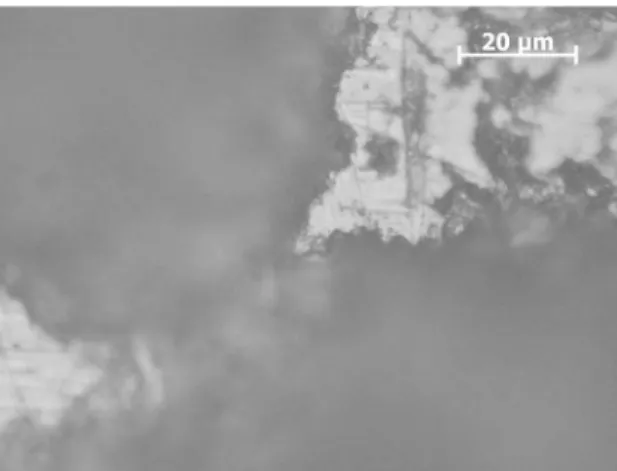
The metallic corrosion process in its microscopic form occurs preferably between grains, since in these regions there is a greater concentration of free energy. Figure 6 shows the detail of a surface region of a test body that sufered the corrosion process, exposed to biogas in natura. In the detail it can be observed that there has been the removal of grains, resulting in an uneven surface. The grains removal process can be easily explained by the weakening of the grain contouring, by the corrosion process, allowing those grains least accommodated in the structure to be easily lost. Figure 7 shows the corroded surface of a test body of the steel ASTM 516 submitted to corrosion in the chimney. In
Figure 6: Detail of the corroded surface of a test body of the steel
ASTM A178, with an increase of 500x.
Figure 7: Detail of the corroded surface of a test body of the steel
ASTM A516, exposed to combustion gases in the chimney, for 314 hours. Increase of 500x.
both cases it is evident that the corrosion process promoted the removal of whole grains.
3.2.2 Scanning electronic microscopy (SEM) of the exposed surfaces
The micrographs of Figure 8 present the corroded surfaces of the test bodies of the steel ASTM A178 for the mounting positions 1 and 2 (in biogas feeding duct and inside the furnace).
The micrographs of Figure 9 present the corroded surfaces of the test bodies of the steel ASTM A516, for the mounting positions 1 and 2 (in biogas feeding duct and inside the furnace).
In the Figures 8a and 9a, with the steels ASTM A178 and ASTM A516 in contact with biogas in natura, the corrosion observed presents cavities with circular edges of varying sizes, over the whole surface of the test bodies.
Figure 8: Corroded surface of test body of the steel ASTM A178. a) Mounted in direct contact with biogas in natura. Increase 120x. b) Mounted in direct contact with the lame of biogas. Increase 120x.
Figure 9: Corroded surface of test body of the steel ASTM A516. a) Mounted in direct contact with biogas in natura. Increase 120x. b) Mounted in direct contact with the lame of biogas. Increase 120x.
directly exposed to lame, is more localized, with smaller-size cavities, presenting a more regular surface.
Although the micrographs suggest a process of softer corrosion, the evaluation of mass loss demonstrates the opposite efect, which is explained by the peeling observed in the test bodies mounted exposed directly to the lame.
3.2.3 Energy dispersive spectroscopy (EDS)
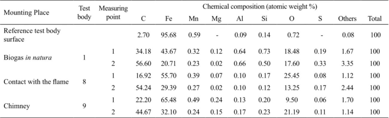
Tables 1 and 2 present the results of the EDS analysis of the surfaces of the test bodies of the materials ASTM A178 and ASTM A516, respectively. The irst line of each table refers to the EDS analysis of the surface of the cross section of the test bodies, properly attacked. The other lines refer to corroded surface of the other test bodies.
The evaluation of the chemical elements present on the surface of the reference test bodies of the ASTM A178 and ASTM A516 steels, indicates the presence of the elements provided for these materials (C and Fe) and a slightly higher presence of Mn in the steel ASTM A516.
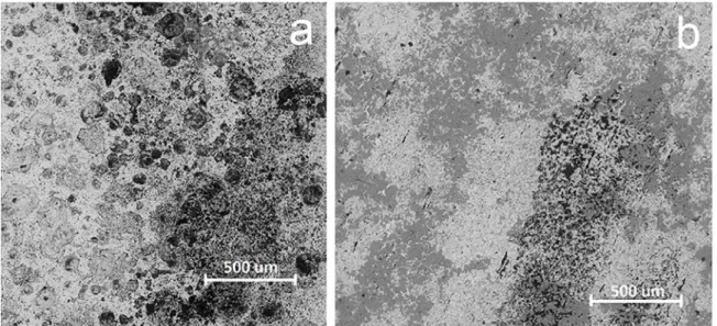
The micrographs of Figure 10 show regions of dark gray and black color, of marked presence in the corroded surfaces, in both materials analyzed. Analysis by EDS in these regions (highlighted as positions 1 and 2 in these micrographs revealed a high carbon content, which may be associated with the presence of the cementite phase).
Table 1: Results of the EDS analysis of test bodies of the steel ASTM A178.
Mounting Place Test body
Measuring point
Chemical composition (atomic weight %)
C Fe Mn Mg Al Si O S Others Total
Reference test body
surface 2.70 95.68 0.59 - 0.09 0.14 0.72 - 0.08 100
Biogas in natura 1 1 34.18 43.67 0.32 0.12 0.64 0.73 18.48 0.19 1.67 100
2 56.60 20.71 0.23 0.02 0.66 0.50 17.60 0.33 3.35 100
Contact with the lame 8 1 16.92 55.70 0.39 0.07 0.10 0.17 25.45 0.08 1.12 100
2 54.24 29.39 0.27 0.02 0.10 0.12 13.25 0.17 2.44 100
Chimney 9 1 22.20 65.48 0.49 0.24 0.13 0.20 9.50 0.06 1.70 100
2 44.67 32.10 0.24 0.15 0.17 0.23 21.19 0.11 1.14 100
Table 2: Results of the EDS analysis of test bodies of the steel ASTM A516.
Mounting Place Test body
Measuring point
Chemical composition (atomic weight %)
C Fe Mn Mg Al Si O S Others Total
Reference test body
surface 2.87 95.30 0.74 0.29 - - 0.80 - - 100
Biogas in natura 1 1 59.19 15.45 0.11 0.07 0.19 0.06 20.29 0.60 4.04 100
2 58.30 6.17 0.06 1.09 2.33 0.13 27.25 0.08 4.59 100
Contact with the lame 8 1 17.46 47.53 0.27 0.34 0.23 0.42 25.01 0.15 8.59 100
2 33.40 31.71 0.23 0.29 4.34 0.24 21.29 0.15 8.35 100
Chimney 10 1 18.66 56.86 0.31 0.22 0.23 0.14 22.40 0.02 1.16 100
2 50.98 20.96 0.20 0.77 1.01 0.20 22.19 0.13 3.56 100
Figure 10: Corroded surface of a test body, mounted in contact with the combustion gases, in the chimney. Increase 500 x. a) Steel ASTM A178. b) Steel ASTM A516.
carbon present in cementite, which surrounds the ferrite α and austenite γ grains, which were removed by the corrosion process, remaining only the constituent cementite.
The micrographs of Figure 11 present the surfaces of the test bodies of steel ASTM A178 and ASTM A516 that were mounted directly exposed to the lame. In these surfaces is possible to observe the graphitization process, with formation of graphite deposits, where cracks present are resulting from the retraction process due to heating and
cooling cycles of the material. The graphitization can be conirmed by the comparison of these micrographs with the carbon contents of Tables 1 and 2 (obtained by EDS analysis) of these regions, which have high carbon content. The test bodies of these materials, which were exposed to biogas in natura and combustion gases present in the chimney, do not present this type of supericial formation.
Figure 11: Corroded surface of a test body , mounted in direct contact with the lame of biogas for 314 hours, showing the cracks present in the cementite. Increase 2500 x. a) Steel ASTM A178. b) Steel ASTM A516.
material lost in the corrosion process, carries with it whole grains of steel, remaining only the cementite inclusions initially present in the grain boundaries.
3.2.4 X-ray difraction (XRD)
Figures 12 and 13 present the lines of the difratograms of the exposed surfaces of each test body of the materials ASTM A178 and ASTM A516, respectively, which show an incidence of ferrite α with greater intensity in the 45 degree angle (plane 110), but also in the angles of 65 degrees and 83 degrees (planes 200 and 211) which, according to Cai et al.19 show to have a greater presence of ferrite α in these
materials. The presence of austenite γ occurs more discreetly, being recorded a line in the 43 degree angle (plane 111).
A direct comparison between the difratograms of the reference test bodies with the other test bodies of each material shows that the corrosion process, under the conditions of
Figure 12: Comparison between the difratograms of the test bodies of steel ASTM A178.
Figure 13: Comparison between the difratograms of the test bodies of steel ASTM A516.
the tests performed, does not cause signiicant changes in the phases present in their crystalline structure, maintaining a greater presence of ferrite α and a discreet presence of austenite γ.
According to Cai et al.19 the main peak of cementite
was observed at 44 degrees, and may be superimposed on the peak of the ferrite α (45 degrees), or absent, due to the technical limitation of X-ray difraction when there is a small presence of phase in the matrix of these steels.
3.3 Supericial hardness
Figure 14: Average supericial Hardness of the test bodies of steel ASTM A178 and ASTM A516.
It is also observed that there was a signiicant reduction in the surface hardness of the test bodies that were submitted to corrosion, exposed directly to the combustion lame of biogas. The test body of steel ASTM A516 that suffered corrosion exposed directly to the combustion lame of the biogas, presented a variation in surface hardness, which can be neglected when it is considered the conidence interval. The test bodies that were exposed directly to the combustion lame of the biogas presented a more signiicant reduction in its surface hardness, more discreetly in the steel ASTM A516 and more signiicantly in the steel ASTM A178. This reduction in surface hardness can be attributed to the presence of the cementite layers, with the presence of the cracks resulting from the retraction process, due to the cooling of the material.
4. Conclusions
The chemical composition and the presence of alloying elements in the steel structure inluence its resistance to corrosion by hydrogen sulide, under diferent conditions.
The “heat stress” caused by heating and cooling cycles are of great importance for the determination of the useful life of a heat-generator boiler, that uses biogas in natura as fuel. The corrosion caused by hydrogen sulide present in biogas in natura, does not alter signiicantly the crystalline structure of the steel exposed to diferent conditions of use of this biogas, as fuel for steam-generating boilers.
The corrosion caused by hydrogen sulide causes greater inluence on the surface hardness of the steel ASTM A178 especially when directly exposed to the combustion lame of biogas.
In the project of structural elements of a steam-generator boiler that use biogas in natura as fuel, knowledge of the corrosion rate to that those elements will be subject and the determination of the estimated useful life of these elements allows to deine the “C” factor proposed by ASME13. For the
project of an equipment, for which it is common a useful life of up to 25 years, corrosion rates of less than 1 mm per year would be admitted for the steel ASTM A516, which is used for the manufacture of structural elements that do not should be replaced in steam-generator boilers.
Once the tubes manufactured with steel ASTM A178 has as main function to promote the heat exchange between the combustion gases and water, turning it into steam, a signiicant increase in the thickness of these elements, by way of over-thickness to corrosion, will result in a reduction of the boiler performance, and consequent increase in fuel consumption. Thus, knowledge of the expected corrosion rate for this material will allow to estimate a useful life for these elements, since their replacement during the useful life of the equipment is expected. It is possible to admit corrosion rates of 1.5 to 2 mm per year for these elements.
The combustion gases present in the chimney, where the lower temperature the corrosion process is more aggressive with increasing of corrosion rates with time, regardless of the chemical composition of the steel. In this case, other factors may be involved, such as chemical reactions. Thus, the use of less noble materials are possible, such as low carbon steels and without alloying materials (lower cost) in the manufacture of the elements that are not subjected to the stresses caused by the internal pressure of the boiler, such as gas pipelines and the chimney itself.
5. Acknowledgments
This work was developed with the support of the Itaipu Technological Park Foundation - Brazil (FPTI-BR) and CIBiogás-ER, by the structure and assistance made available, allowing the development of this work in the facilities of “Condominium Ajuricaba” in the city of Marechal Cândido Rondon - PR. The companies H. Bremer & Filhos Ltda., In the person of D. Lilian Bremer Vogelbacher, for making available the materials used in experiments. The authors acknowledge the Center for Materials Characterization and Development of the Department of Materials of UFSCar, and all its team, for the micrographic analysis and characterization, performed on test bodies.
6. References
1. Schafer JV, Alves HJ, Marin Neto AJ, Lopes DG, Kugelmeier CL, Santos GR. Potencial de Produção de Hidrogênio a partir da Reforma Catalítica do Biogás na Região Oeste do Paraná.
Revista Tecnológica. 2014;23(1):119-129.
2. Carvalho Júnior JA, McQuay MQ. Princípios de Combustão Aplicada. Florianópolis: Editora da UFSC; 2007.
3. Demirbas A. Potential applications of renewable energy sources,
biomass combustion problems in boiler power systems and
combustion related environmental issues. Progress in Energy
and Combustion Science. 2005;31(2):171-192. DOI: 10.1016/j. pecs.2005.02.002
4. Saidur R, Abdelaziz EA, Demirbas A, Hossain MS, Mekhilef S. A review on biomass as a fuel for boilers. Renewable and Sustainable Energy Reviews. 2011;15(5):2262-2289. DOI: 10.1016/j.rser.2011.02.015.
6. Moreira RM. Avaliação da Resistência à Corrosão dos Aços Inoxidáveis 13Cr e 13Cr-5Ni-2Mo em Meios Úmidos de CO2 e
H2S Presentes em Colunas de Produção de Petróleo. [Thesis]. Florianópolis: Federal University of Santa Catarina; 2004.
7. MacDonald DD, Roberts B, Hyne JB. The corrosion of carbon steel by wet elemental sulphur. Corrosion Science. 1978;18(5):411-425. 8. Hansen LA, Nielsen HP, Frandsen FJ, Dam-Johansen K, Hørlyck
S, Karlsson A. Inluence of deposit formation on corrosion at a straw-ired boiler. Fuel Processing Technology. 2000;64(1-3):189-209. DOI: 10.1016/S0378-3820(00)00063-1.
9. Michelsen HP, Frandsen F, Dam-Johansen K, Larsen OH. Deposition and high temperature corrosion in a 10 MW straw ired boiler. Fuel Processing Technology. 1998;4(1-3):95-108. DOI: 10.1016/S0378-3820(97)00062-3.
10. Frandsen FJ. Utilizing biomass and waste for power production-a
decade of contributing to the understanding, interpretation
and analysis of deposits and corrosion products. Fuel. 2005;84(10):1277-1294. DOI: 10.1016/j.fuel.2004.08.026.
11. Yilbas BS, Arif AFM, Abdul Aleem BJ. Laser welding of low carbon steel and thermal stress analysis. Optics & Laser Technology. 2010;42(5):760-768. DOI: 10.1016/j.optlastec.2009.11.024. 12. American Petroleum Institute (API). API RP 571 - Damage
Mechanisms Afecting Fixed Equipment in the Reining Industry. Washington: American Petroleum Institute; 2011.
13. American Society of Mechanics Engineers (ASME). Power
Boilers - Section I - Rules for Construction of Power Boilers. New York: ASME; 2013
14. Jenkins BM, Baxter LL, Miles TR Jr, Miles TR. Combustion properties of biomass. Fuel Processing Technology. 1998;54(1-3):17-46.
15. American Society of Mechanics Engineers (ASME). Boiler and Pressure Vessel Code, Section II, Materials - Part A - Ferrous Material Speciications. New York: ASME; 2013.
16. CIBiogas-ER. 2015. Available from: <http://www.cibiogas.
org>. Access in: 12/1/2015.
17. ASTM International. ASTM G1 - 03 - Standard Practice for Preparing, Cleaning, and Evaluating Corrosion Test Specimens. West Conshohocken: ASTM International; 2011. DOI: 10.1520/ G0001-03R11.
18. ASTM International. ASTM E18 - 16 - Standard Test Methods for Rockwell Hardness of Metallic Materials. West Conshohocken: ASTM International; 2014. DOI: 10.1520/E0018-14. 19. Cai ZH, Ding H, Misra RDK, Kong H, Wu HY. Unique impact
of ferrite in inluencing austenite stability and deformation behavior in a hot-rolled Fe–Mn–Al–C steel. Materials