Development of an Electronic Warfare Package Diogo Santos Pinto da Costa Teles
Dissertação para obtenção do grau de Mestre em Ciências Militares Navais, na especialidade de Engenharia Naval – Ramo de Armas e Eletrónica
Alfeite 2019
Development of an Electronic Warfare Package Diogo Santos Pinto da Costa Teles
Dissertação para obtenção do grau de Mestre em Ciências Militares Navais, na especialidade Engenheiros Navais – Ramo de Armas e Eletrónica
Orientação de: CTEN EN-AEL Monteiro Marques Coorientação de: Professor Doutor Vítor Lobo
O Aluno Mestrando ________________________
ASPOF EN-AEL Costa Teles
O Orientador
________________________ CTEN EN-AEL Monteiro Marques
Alfeite 2019
“There is much more to electronic warfare than simply detecting enemy transmissions.” Martin Van Creveld Technology and War, 1989
VII
Acknowledgements
I couldn’t complete this thesis without the support of several people and entities. So, I would like to thank:
• First of all, my mother and my sister that gave me the education and support that allowed me to be who I am;
• My closest friends which have been of major importance in my life, along with “Curso Jorge Álvares”;
• ASPOF Hipólito Lopes and ASPOF Rodrigues Marante with whom I’ve worked together in a group effort to improve Navy’s capacities;
• CTEN Monteiro Marques for the supervision of my thesis and all the guidance provided; • Professor Victor Lobo for all the help and for providing the opportunity of developing my
thesis in the way I did;
• 1TEN Gonçalves Capela for all the help on the software development and guidance; • UAVision for the help and resources provided for the software and hardware development; • CTEN Silva Ângelo and 1TEN Seixas Nunes from CITAN for all the help given that contributed
actively for the realization of this thesis;
• 1TEN Mendes Lança and all CEOV team for the advices and contributions; • CMG Farinha Alves for the help on the execution on the tests and experiments;
• All the Portuguese Marines Electronic Warfare Section for the help and support on the execution of tests and experiments and the shared knowledge;
• Crew of NRP D. Francisco de Almeida, which provided me an excellent internship and the opportunities to write this thesis;
• Crews of NRP Álvares Cabral, NRP Vasco da Gama and NRP António Enes for the support on the execution of several tests and experiments;
• TCOR Paulo Rosendo, CAP João Chora and 1SAR Joaquim Machado from the Anti-Air Artillery Regiment Nº1 and Artillery Regiment Nº5 for the help provided;
• 1TEN Ramos Maia and 1SAR Duarte Guerra from CADOP for the information provided; • Finally, I’d like to thank to people that positively shaped my life through the Naval Academy,
IX
Abstract
Nowadays with the development and cost reduction of unmanned vehicles, armed forces around the world have been using these systems as a replacement or complement for conventional manned systems. Because of all the advantages inherent to the use of these vehicles, there have been many possible applications for these systems. One of possible applications is its use as a vehicle for carrying an Electronic Warfare package. Electronic Warfare, since the military started using and depending on the electromagnetic spectrum to achieve their objectives, has been a major warfare area of high interest.
In my thesis, I suggest the creation of an Electronic Warfare package with jamming and spoofing capacities for communication systems, designed to be implemented on an unmanned vehicle, with remote control dedicated programs. To do this, I took advantage of the Software Defined Radio technology along with the GNU Radio software, installed on a Raspberry Pi computer in order to be transportable even by small vehicles.
Keywords: Unmanned Vehicles; Electronic Warfare; Software Defined Radio; GNU Radio; Jamming; Spoofing
XI
Resumo
Atualmente, com o desenvolvimento e a redução de custos dos veículos não tripulados, as forças armadas em todo o mundo têm utilizado estes sistemas como substituto ou complemento aos sistemas tripulados. Devido às vantagens inerentes à sua utilização, têm havido inúmeras aplicações para estes sistemas. Uma das possíveis aplicações é a sua utilização como veículo para transporte de um pacote de Guerra Eletrónica. A Guerra Eletrónica, desde que os militares começaram a utilizar e a depender do espetro eletromagnético para alcançar os seus objetivos, tem sido uma das principais áreas da guerra de elevado interesse.
Nesta dissertação, sugiro a criação de um módulo de Guerra Eletrónica com a capacidade de efetuar empastelamento e mistificação de a sistemas de comunicações, idealizado para ser implementado num veículo não tripulado, com programas dedicados para controlo remoto. Para isto, recorri à tecnologia do Radio Definido por Software assim como ao software GNU Radio, instalado num computador Raspberry Pi por forma a poder ser transportado também por pequenos veículos.
Palavras-Chave: Veículos não Tripulados; Guerra Eletrónica; Rádio Definido por Software; GNU Radio; Empastelamento; Mistificação
XIII
Contents
List of Figures ... XV
List of Tables ... XVI
Acronyms ... XVII
1
Introduction ... 1
1.1 Motivation ... 1 1.2 Research Question ... 2 1.3 Research Method ... 2 1.4 Thesis Structure ... 22
Background ... 5
2.1 Electronic Warfare in NATO ... 8
2.2 Jamming Techniques ... 12
2.3 Jammer Types ... 12
2.4 Identification of the bands, systems and applicability on Naval Operations ... 17
2.4.1 AIS ... 17
2.4.2 ISM Band ... 18
2.4.3 GNSS ... 19
3
Software, Hardware and Interface Development... 21
3.1 Definition of the Hardware ... 21
3.1.1 SDR ... 21 3.1.2 HackRF One ... 22 3.1.3 GNU Radio ... 23 3.1.4 Raspberry Pi ... 23 3.2 Software Development ... 24 3.2.1 AIS Jammer: ... 24 3.2.2 Free Jammer ... 27 3.2.3 Wi-Fi Jammer ... 29
XIV
3.2.5 GNSS Jammer... 32
3.2.6 AIS Spoofer ... 34
3.2.7 Remote Control ... 40
4
Experiments and Results ... 43
4.1 Portuguese Naval Academy Test ... 43
4.2 Portuguese Marines Base Test ... 46
4.3 Lisbon Naval Base Test ... 48
4.4 NRP Álvares Cabral Test ... 49
5
Conclusion ... 51
5.1 Future Work ... 526
Bibliography ... 53
7
Appendixes ... 57
7.1 Appendix A - Client ... 57 7.2 Appendix B - Server ... 61XV
List of Figures
Figure 1 - Overview of EW [4] ... 7
Figure 2 - EM Operations Concept [10] ... 8
Figure 3 - EM Actions and Effects [14]... 9
Figure 4 - Relationship between the several areas of EW [14] ... 10
Figure 5 - Five jammer spectral densities types [17] ... 13
Figure 6 - Comparison between a rectangular and a spread spectrum signal in the presence of a barrage jammer [18] ... 14
Figure 7 - Types of jammers by [12] ... 15
Figure 8 - AIS Jammer Client Block Diagram ... 25
Figure 9 - AIS Jammer Server Block Diagram ... 26
Figure 10 - Information sent to the HackRF by the “Add” Block ... 27
Figure 11 - Free Jammer Client Block Diagram ... 28
Figure 12 - Free Jammer Server Block Diagram ... 29
Figure 13 - Wi-Fi Jammer Client Block Diagram ... 30
Figure 14 - Wi-Fi Jammer Server Block Diagram ... 30
Figure 15 - Wi-Fi Jammer All Band Server Block Diagram ... 31
Figure 16 - GNSS Jammer Client Block Diagram ... 32
Figure 17 - GNSS Jammer Server Block Diagram ... 33
Figure 18 - AIS Spoofer Client Block Diagram ... 34
Figure 19 - AIS Spoofer Server Block Diagram ... 37
Figure 20 - EW Package Physical Architecture ... 41
Figure 21 - EW Package Functional Architecture ... 42
Figure 22 - Spectrum Analyser Screenshot ... 43
Figure 23 - Jammer set on the Naval Academy’s Test ... 45
Figure 24 - Naval Academy's Jamming Test... 46
Figure 25 - Portuguese Marines container and Parrot Bepop 2 ... 47
Figure 26 - Portuguese Marines Base Jamming Test ... 47
Figure 27 - Naval Base Test Fixed-Wing UAV Flight Plan ... 48
Figure 28 - "Dynamic - Both" Test ... 49
XVI
List of Tables
Table 1 - EP Actions in Modern Anti-Ship Missiles ... 6
Table 2 - Proactive Jammers ... 16
Table 3 - Reactive Jammers ... 16
Table 4 - Function-specific Jammers ... 16
Table 5 - Smart-hybrid Jammers... 17
Table 6 - ISM Band Frequencies ... 19
Table 7 - Comparison between SDRs ... 22
Table 8 - Comparison between single board computers ... 24
Table 9 - AIS Dynamic Message Sentence ... 37
Table 10 - AIS Static Part A Message Sentence ... 38
XVII
Acronyms
AAW – Anti-Air Warfare
AIS – Automatic Identification System ASMD – Anti Ship Missile Defence ASW – Anti-Submarine Warfare ASuW – Anti-Surface Warfare
AWGN – Additive White Gaussian Noise C2 – Command and Control
COMINT – Communications Intelligence COTS - Commercial Off the Shelf
CTS – Clear to Send CW – Continuous Wave DSP – Digital Signal Processing
DSSS - Direct-sequence spread spectrum EA – Electronic Attack
ECM – Electronic Counter Measures ED – Electronic Deception
ELINT – Electronic Intelligence EM – Electromagnetic
EME – Electromagnetic Environment EP – Electronic Protection
ES – Electronic Warfare Support ETA – Estimated Time of Arrival EW – Electronic Warfare
GCS – Ground Control Station
GNSS – Global Navigation Satellite System GPP - General Purpose Processors
GPS – Global Positioning System IF – Intermediate Frequency
XVIII IP – Internet Protocol
ISM – Industrial, Scientific and Medical
ISR – Intelligence, Surveillance and Reconnaissance
ISTAR - Intelligence, Surveillance, Target Acquisition and Reconnaissance ITU – International Telecommunications Union
IW – Information Warfare
NATO – North Atlantic Treaty Organization PNT – Positioning, Navigation and Timing PSD – Power Spectral Density
RF – Radio Frequency RTS – Request to Send
SDR – Software Defined Radio SIGINT – Signal Intelligence SNR – Signal to Noise Ratio SOLAS – Safety of Life at Sea UAS – Unmanned Aerial System UAV – Unmanned Aerial Vehicle US – United States
UxS – Unmanned Systems VHF – Very High Frequency
1
1 Introduction
In this chapter, there will be presented the motivation, research question and hypothesis and the structure of the thesis.
1.1 Motivation
Nowadays unmanned systems (UxS) and systems are an accessible tool for almost everyone. The technological advances allow us to buy UxS for relatively low prices. This is having an impact on how military and civilian operations are being carried out [1], causing UxS to operate on more complex missions where higher levels of situational responsiveness and autonomous decision making are necessary [2]. In today’s battlefields, UxS are highly integrated on the environment, bringing new intelligence, surveillance and reconnaissance (ISR) and tactical support capabilities to military forces [3], trading the risk of losing human life by systems. With this, the military around the world are exploiting the UxS potential in the various warfare areas, including Electronic Warfare (EW).
Electronic Warfare is major warfare area comprehending any action on the electromagnetic (EM) environment. Because military forces are becoming highly dependent on EM spectrum operations, they recognize its vulnerabilities and the importance on controlling this warfare environment [4]. On the last decade, there were many examples of how military forces are vulnerable to EW actions. On the 12th of April 2014, the Russian military claimed that they disabled the Aegis Combat system of the US Navy destroyer USS Donald Cook with an EW payload [5]. Also, during the North Atlantic Treaty Organization (NATO) exercise “Trident Juncture 2018”, the Swedish claimed that the Russian military tried to jam the Global Positioning System (GPS) and that this wasn’t the first time they did so [6].
Because EW is an area of great interest to the military around the world, including the Portuguese Navy, this thematic proved to me a big motivation to develop additional work in this area.
2
1.2 Research Question
As stated before, in the last years UxS became a reality on modern battlefield scenarios, changing the way military operations are carried out. Along with this, EW represents an area of great importance to military forces. Combining these two subjects in one allows the formulation of the following research question:
“Is it possible to implement an EW package on an UxS using low-cost technologies with the purpose of improving the EW capacities for the Portuguese Navy?”
To answer this question, the following hypothesis is proposed:
“By using an SDR transceiver and a Raspberry Pi computer, it is possible to build a device with jamming and spoofing capabilities on various communication systems, capable of being implemented on an UxS.”
1.3 Research Method
The research method is done according to [7] and [1]. First, a research question is formulated in order to set a goal and purpose for the thesis. Next, a research background is made were a research about the subject and related work is made. This is followed by the hypothesis formulation where is proposed a solution for the research question. The next step is the design experiment where the proposed solution in executed. Next, is the hypothesis test in which the designed experiment is tested. After, is the interpretation and analysis of the results and finally, the publishing of the results in order to share the developed work with the scientific community.
1.4 Thesis Structure
This thesis is divided in five chapters. In the first chapter, the motivation that led to the development of this work, the chosen research method and the explanation on the thesis’ structure are presented.
The second chapter is where the research of the background is done. There is an explanation on EW basics, existing jamming techniques and types, and the systems that compose the capabilities of the EW package and their importance.
3 In the third chapter it is presented all the necessary hardware interface a software programming necessary to create Electronic Attacks to the systems described on the second chapter.
The fourth chapter is where the tests and results made in order to prove and validate the capacities of the EW package, are presented.
Finally, in the fifth chapter, conclusions are made in accordance to the suggested hypothesis along with suggestions for future work on the theme.
5
2 Background
In this chapter, an introduction to EW is made, as well as an explanation of its divisions. Also, several Jamming techniques and jammer types are presented along with the identification of the bands, systems and application on naval operations where the EW package might apply, including a brief analysis of the importance and applicability of EW in the North Atlantic Treaty Organization.
Information Warfare (IW) are the warfare-like actions against any information system or the measures to protect our own systems. The IW applied military setting is Command and Control (C2) warfare which is composed by: physical destruction of information systems, psychological operations, deception, operational security and EW [8]. The latter is the focus of my thesis.
EW is defined as the military action involving the use of the EM spectrum and directed energy to control the EM spectrum or to attack the enemy [9]. In this definition, no reference is made to the equipment used but to the objective and purpose of the mission and because of this, EW is a vast concept that covers several operations.
EW can be divided by the type of operation in three categories: Electronic Attack (EA), Electronic Protection (EP) and Electronic Warfare Support (ES) [10].
According to [9] and [10]:
Electronic Attack is the division of EW involving the use of electromagnetic or directed energy to attack personnel, facilities or equipment with the intent of neutralizing or destroying the enemy’s combat capability. It can be sub-divided in jamming, deception, anti-radiation missiles and directed energy weapons.
Jamming is the most common sub-division of EA. Jamming is the emission of EM energy with the objective of interfering with the enemy’s use of the EM spectrum. Jamming can be divided in two divisions according to the type of signal: Radar Jamming and Communications Jamming. In EW applied to communications, the purpose of jamming is to break the enemy’s communications link, denying them access to the content of a transmitted emission and, thereby, preventing them from access desirable
6 information [11]. Jammers can have different configurations. For example, there are standoff jammers which are the ones that operate in the friendly held battlespace, stand-in jammers that operate in the hostile held battlespace, the narrowband jammers that only attack the carrier frequency and the barrage jammers that emit a broad range of frequencies simultaneously [8].
Electronic Protection is the division of electronic warfare involving actions taken to protect personnel, facilities and equipment from any effects of friendly or enemy employment of EW that degrade, neutralize or destroy friendly combat capability. This includes the employment of techniques in order to minimize the effects of enemy’s or friendly’s EA and ES actions [12]. The following table lists some of the available EP techniques used by modern anti-ship missiles:
Table 1 - EP Actions in Modern Anti-Ship Missiles
Missile Country of Origin EP Action
Harpoon Block 1C United States of America Frequency Agility
Harpoon Block 2 Unites States of America Doppler Processing
Exocet MM40 Block 2 France
Frequency Agility / Leading Edge Track /
Home-on-Jam
Exocet MM40 Block 3 France Doppler Processing
RBS 15M/F/K Sweden
Frequency Agility / Jittered PRF /
Home-on-Jam
RBS 15 Mk3 Sweden FM-CW
SS-N-22 Russia Supersonic / Passive ARM
SS-N-25 Russia Passive ARM / Coherent
Processing
SS-N-27 Russia Zigzag Flight Path
7 Electronic Warfare Support is the division of electronic warfare involving actions tasked by, or under direct control of, an operation commander to search for, intercept, identify and locate sources of intentional and unintentional radiated EM energy. Even though ES and signal intelligence (SIGINT) [which is includes communications intelligence (COMINT) and electronic intelligence (ELINT)] both include receiving enemy transmissions, they are differentiated in the purpose for which the transmissions are received. In COMINT and ELINT the received enemy signals (communication and noncommunication) are used to gather intelligence from the carried information in the signals and to determine details of the enemy’s EM systems. On the other hand, ES is the collection of enemy signals (communication and noncommunication) with the purpose of taking and action against the signal or the associated weapon with these signals [13].
In the following figure, the three divisions of EW are presented along with the types of operations applicable to each one:
Figure 1 - Overview of EW [4]
These divisions evolved from the former definitions that were Electronic countermeasures (ECM), Electronic counter-countermeasures (ECCM) and Electronic warfare support measures (ESM).
8
2.1 Electronic Warfare in NATO
EW in the NATO is defined as “The military action that exploits EM energy to provide situational awareness and achieve offensive and defensive effects. EW, the conduct of EM Operations (Figure 2), is warfare in the Electromagnetic Environment (EME)” [14].
Figure 2 - EM Operations Concept [10]
NATO also acknowledges that the dependency of electronics in the modern battlefields and the threat posed to NATO by the increased EW potential of its adversaries, increase its need of controlling the EM environment by having an effective EW doctrine defined by NATO as “the best way to accomplish Joint EW operations”. Specifically, EW has a crucial role in the C2 Warfare and Information Operations, being considered a central discipline of both. Another importance of EW is that the Rules of Engagement my often permit EW when other activities are inappropriate.
The uses of EW in NATO include the control of the EM spectrum to ensure provision, protection, exploitation and attack of C2 and other battlespace electronic systems; area, force or platform protection; Intelligence, Surveillance, Target Acquisition and Reconnaissance (ISTAR) and offensive and defensive operations.
There are three possible EW actions: EA, Electronic Defence and Electronic Surveillance, described in Figure 3:
9
Figure 3 - EM Actions and Effects [14]
Electronic Jamming is a considered a type of operation of Electronic Counter Measures (ECM). In NATO operations, Electronic Support Measures, Electronic Counter Measures and Electronic Protective Measures are to be used as EW divisions instead of EA, EP and ES definitions used by some authors and some countries like the United States. Electronic Jamming is defined by NATO [14] as “the deliberate radiation, re-radiation or reflection of EM energy, with the objective of impairing the effectiveness of electronic devices, equipment or systems being used by an adversary. Co-ordination of jamming operations is a J3 (Current Operations) responsibility in consultation with J2 (Operational Intelligence), J6 (Communications and Information Systems) and the Electronic Warfare Coordination Cell (EWCC). Co-ordination and planning are conducted at the highest level of command, but control should be vested in the appropriate operational commander.”
Another important type of operation of ECM is Electronic Deception (ED). Electronic Deception, according to NATO [14], is “the deliberate radiation, re-radiation, alteration, absorption or reflection of EM energy in a manner intended to confuse, distract or seduce an adversary or his electronic systems.” ED can also be used to assist
10 with military deception, principally against communications systems. Therefore, ED should be considered during the development of any deception plan. The J2 staffs provide information on the adversary’s use of the EM spectrum, vulnerability, surveillance capabilities, and their likely reaction to deception, while the EW staffs provides the intelligence staff with reports indicating their actual reaction to implemented ED operations.
ED is considered effective when the adversary relies heavily on EM emissions (which may cause the adversary to react in a manned prejudicial to his interests by manipulating, distorting or faking its transmissions), when the adversary is dependent on the intercept of our EM emissions for his own intelligence collection or at a critical time in the adversary’s operations.
On Figure 4 is shown the relationship between the different areas in EW and in the EM environment:
Figure 4 - Relationship between the several areas of EW [14]
For NATO, the applicability of EW in Naval operations is vast. Naval forces, acting alone or in a Joint Force use all aspects of EW in order to perform their tasks. Especially
11 when applying the principles of EW in amphibious operations, anti-surface warfare (ASuW), submarine warfare (ASW) and air warfare (AAW) being included anti-ship missile defence (ASMD) in the latter. Naval EW resources are used to deny, deceive destroy or exploit the adversary’s use of the EM spectrum and to protect the use of the EM spectrum for friendly use.
12
2.2 Jamming Techniques
There are several techniques and strategies to make jamming. These techniques vary according to the type of system that we are trying to jam, how much power does it use, the modulation, among others. Also, the duration of the jamming in relation to the total length of the signal is important. For example, in voice communications, it has been demonstrated that jamming about 30% of the transmission is enough to degrade the message to a point where it makes it understandable [15].
In modern communications, there are also several methods of transmitting a signal making it harder to jam. These methods include frequency-hopping, direct sequence or spread spectrum where the signal is spread by the EM spectrum, resulting in a large bandwidth and hard to jam and detect signal.
Another consideration is the possibility of transmitting a signal where the jamming signal is superior to the received signal. As explained by [16] it is possible to communicate over a channel disturbed by Additive White Gaussian Noise (AWGN) and even hide a signal within the noise by using more dimensions than the ones necessary for the transmission.
2.3 Jammer Types
In order to jam a signal, there are several types of jammers that can be used. Each one of them has their advantages and disadvantages and the characteristics of the intercepted signal should be taken into consideration before choosing the type of jammer. According to different authors, there are various ways to classify jammer types.
13
Figure 5 - Five jammer spectral densities types [17]
The first one (a), the barrage jammer, which he considers the least efficient jammer, transmits a band-limited Gaussian noise. This jammer is used to cover a large section of the signal spectrum, simulating the creation of an additional source of AWGN, in order to deny the counteraction of frequency hopping to a jammer-free zone.
However, when these jammers and the signal generators are limited on the power resource of the transmitter, they become vulnerable to spread spectrum techniques, which are the most efficient EP measure against barrage jammers. This is demonstrated in Figure 6 where a rectangular signal (left) and a spread spectrum signal (right) are jammed and, after passing through a matched filter, the spread spectrum signal is easily observable in contrary to the rectangular one [18].
14
Figure 6 - Comparison between a rectangular and a spread spectrum signal in the presence of a barrage jammer [18]
The second one (b), the partial band jammer, is a jammer that only transmits bandlimited AWGN, covering only a part of the signal’s bandwidth. The advantage of these over the barrage jammers is that it can channel more power over one or more desired sections of the signal’s bandwidth, especially if dealing with frequency hopping spread spectrum signals [19].
Tone jamming, the third (c) and fourth (d) on Figure 2, happens when one or more tones are introduced in the signal’s spectrum. Their jamming efficiency depends on the number of tones and on their location (considering the same Power Spectral Density (PSD) of the previous). Typically, on an Unmanned Aerial System (UAS), a tactical jammer is limited to about 100 watts, making the number of tones to be limited to around 10 [15]. As stated before, tone jamming may be divided into single tone jamming and multitone jamming. Single tone jamming also known as a spot jamming, according to [20], is the jamming of a specific or frequency. It’s basically a Continuous Wave (CW) signal transmitted on a single frequency. By deploying single tone jammers against
15 Direct-sequence spread spectrum (DSSS) signals, especially if close to the receiver, the jamming signal causes problems in the gain control systems of the received signal [15]. Multitone jammers are jammers that emit more than one tone, capable of covering a larger bandwidth than a single tone jammer or jamming several channels on a multiple channel receiver [21].
The matched spectral jammer detects the signal’s spectral density and uses a Gaussian random process to create a “matched spectral” jamming signal identical to the original signal [17].
Another way of dividing jammers by type is suggested in [22], for jammers in wireless networks, presented on Figure 7 and detailed on Tables 2, 3, 4 and 5:
Types of Jammers Elementary Proactive Constant Jammer Deceptive Jammer Random Jammer Reactive RTS/CTS Jammer Data/Ack Jammer Advanced Function -Specific Follow-On Jammer Channel Hopping Jammer Pulse Noise Jammer Smart - Hybrid Control Channel Jammer Implicit Jammer Flow Jammer
16
Table 2 - Proactive Jammers
Table 3 - Reactive Jammers
Table 4 - Function-specific Jammers
Proactive Jammers
Jammer that transmits whether there is or there is not data communication.
Constant Jammer Emits random bits continuously Deceptive Jammer Emits regular packets continuously
Random Jammer Emits bits and/or packets intermittently
Reactive Jammer
Jammer that only transmits if data communication is detected
RTS/CTS Jammer
Jams when requests-to-send (RTS) signal is emitted. This prevents de receiver to send the clear-to-send (CTS) signal because the RTS signal
is distorted Data/ACK
Jammer Corrupts the data or acknowledgment packets
Function-specific Jammer
Jammer implemented by having a pre-determined function. It can jam one or multiple channels
Follow-on Jammer
Hops over all available channels, jamming each channel for a short period of time
Channel-hopping Jammer
Hops between different channels, with the possibility of jamming several channels at the same time
Pulsed-noise Jammer
It can switch channels and jam different bandwidths. Like the random jammer but with the possibility of attacking several
17
Table 5 - Smart-hybrid Jammers
2.4 Identification of the bands, systems and applicability on Naval
Operations
In this sub-chapter, there are going to be presented the different bands and systems where the jammer works.
2.4.1 AIS
The Automatic Identification System (AIS) is a Very High Frequency (VHF) transponder system with an automatic identification capacity, developed by the International Maritime Organization, in the sequence of the revision of Chapter V of the Safety of Life at Sea (SOLAS) Convention [23]. It was designed as a navigation safety aid and as an environmental protection aid, through the exchange of information between ships and coast stations [24].
Because this system is mandatory for every ship with 300 or more gross tonnage and all passenger vessels and highly recommended for all ships, almost every vessel uses this system [25]. Also, according to the MarineTraffic website [26], AIS information is used to serve several purposes such as tug operations, communication between vessel crews and their family’s members, coast guard and border patrol operations, environmental protection agencies, among others.
Smart-hybrid Jammer
Jammer with the capacity of conserving energy by emitting only the necessary power to disrupt the channel (smart). It can be either proactive or reactive (hybrid)
Control Channel Jammer
Multi-channel jammer that targets the control channel used to coordinate the network activity
Implicit Jammer Jammer that disables the functionality of the target and causes denial-of-service, by targeting the nodes of the access point Flow-jamming
18 The AIS transmits a great variety of information about the ship such as: GPS data (position, course and speed), data from the gyrocompass, International Maritime Organization (IMO) number, call sign, length and beam, location of the antenna, ship type and draft, hazardous cargo, destination, Estimated Time of Arrival (ETA) and route plan. Its data that can be programmed into the unit because it never changes is known as static data like the IMO number, the data introduced by the user is known as voyage related data, like the route plan and the data that’s being constantly updated (automatically) is known as dynamic data, like the ships’ position.
The AIS works on VHF channel 87B and 88B at 161.975 MHz and 162.025 MHz respectively with a transmission bit rate of 9600 baud. It uses Self Organizing Time-Division Multiple Access in order to avoid collisions between the transmissions of the different stations, using the GPS time as a common time reference. AIS messages are standardized hence, it’s relatively easy to create messages or to change their content directly on the raw code [27]. This makes them rather vulnerable to jamming and spoofing, and thereby, a good and easy target to perform electronic attacks. There are tactical situations where it could be useful to create “ghost contacts” in order to baffle the enemy’s perception of the surrounding environment. On the other hand, it might also be useful to deny them all AIS information by jamming the system.
2.4.2 ISM Band
The Industrial, Scientific and Medical (ISM) band are parts of the EM spectrum allocated for Radio Frequency (RF) use of industrial, scientific and medical equipment. According to the International Telecommunications Union (ITU) [28], ISM band application is the “Operation of equipment or appliances designed to generate and use locally radio frequency energy for industrial, scientific, medical, domestic or similar purposes, excluding applications in the field of telecommunications.” In the definition by ITU, telecommunication applications are not considered because of the RF interference that ISM equipment may cause but, since this band is open and unlicensed, there are also many short-range telecommunications devices using this band.
According to the European Communications Committee [29], the ISM band frequencies in Europe are presented on Table 6:
19
Table 6 - ISM Band Frequencies
ISM BAND FREQUENCIES
Start Frequency End Frequency
11.3 kHz 14 kHz 6765 kHz 6795 kHz 13553 kHz 13567 kHz 26.957 MHz 27.283 MHz 40.66 MHz 40.7 MHz 430.05 MHz 434.79 MHz 2400 MHz 2500 MHz 5725 MHz 5875 MHz 24 GHz 24.25 GHz 61 GHz 61.5 GHz
Many systems that we use on a daily basis work on the ISM band. Some examples of these systems are the IEEE 802.11/Wi-Fi, Bluetooth or car remote controls [30].
2.4.3 GNSS
The satellite navigation is a very important component of modern navigation systems, specially the systems contained in the Global Navigation Satellite System (GNSS). Among the existing GNSSs, three were explored: the GPS, the Globalnaya navigatsionnaya sputnikovaya Sistema (GLONASS) and the Galileo [31].
GPS
The GPS is, according to the United States (US) Government [32], a U.S.-owned utility that provides users with positioning, navigation, and timing (PNT) services. The system uses satellites in order to provide the PNT information. The GPS has many applications worldwide from navigation to clock sensitive systems, which makes it essential for some systems to work properly.
The GPS satellites emit two signals: a civilian which apart of some restrictions, its use is authorized for everyone and a military which is encrypted by the U.S. Department
20 of Defence. The GPS civilian signal works in two frequencies: the L1 and the L2C. The L1 and the L2C are modulated with a carrier wave that works in the frequency 1575.2 MHz and 1227.6 MHz and, just like the AIS signal, its packet information is public, making it vulnerable to electronic attacks [33]. The tactical and strategical advantages of controlling the GPS signal are significant. For example, by denying the enemy the capacity of receiving a GPS signal, several systems are affected, reducing their combat and defence capacity.
GLONASS
The GLONASS is a Russian satellite navigation system like the GPS. It was developed by the Russian Federal Space Agency and also has both a military and a civilian signal. The civilian signals’ frequency is 1602+n*0.5625 MHz and 1246+n*0.4375 MHz, being n the channel number [34].
GALILEO
Just like the US and Russia had the necessity of having an independent satellite navigation system, the European Union also developed its own. Galileo, named after Galileo Galilei, is the European satellite navigation system developed by the European Global Navigation Satellite System Agency [35].
21
3 Software, Hardware and Interface Development
In this chapter, there are presented all the necessary software development and the hardware solutions founded for the creation of the EW package.
3.1 Definition of the Hardware
In this sub-chapter, there will be presented the architecture for the EW package.
3.1.1 SDR
According to different organizations, there are many definitions for Software Defined Radio (SDR) [36]. For example, the ITU defines it as “A radio in which the RF operating parameters of frequency range, modulation type, and/or output power can be set or altered by software, or the technique by which this is achieved”[37] and the U.S. Federal Communications Commission defines it as “A radio that includes a transmitter in which the operating parameters of frequency range, modulation type or maximum output power (either radiated or conducted), or the circumstances under which the transmitter operates in accordance with Commission rules, can be altered by making a change in software without making any changes to hardware components that affect the radio frequency emissions”[38]. Although there are different definitions for SDR, they all state that SDR is a radio platform where we can alter several parameters in software without changing the hardware.
Basically, an SDR is a radio and software technique used in radio communications, where most or all of the signal processing, such as modulation, sampling and waveform synthesis, is done using software routines in general purpose processors (GPP) rather than application-specific hardware (like in hardware-based radios). Digital signal processing (DSP) made in software has several advantages over DSP made in hardware, including higher flexibility and adaptability (routines can be changed during execution) and a reduction of cost inherent to the hardware since general purpose hardware is used. Other two important advantages of using SDRs is the existence of a big online community, offering lots of support (specially for the open source SDRs) and making it accessible and easy to work with, even for people with basic
22 knowledge of signal processing, and the available open source DSP frameworks tailored for SDR applications.
3.1.2 HackRF One
The HackRF one is an open-source SDR half-duplex transceiver designed by Michael Ossmann [39], with operating frequencies from 1 MHz to 6 GHz. It’s able to process 20 million samples per second (being its maximum bandwidth 20 MHz), it connects to a computer through USB and it’s compatible with GNU Radio [40]. Its maximum transmission power is [39]:
• 10 MHz to 2150 MHz: 5 dBm to 15 dBm, generally increasing as frequency decreases • 2150 MHz to 2750 MHz: 13 dBm to 15 dBm • 2750 MHz to 4000 MHz: 0 dBm to 5 dBm, increasing as frequency decreases • 4000 MHz to 6000 MHz: -10 dBm to 0 dBm, generally increasing as frequency decreases
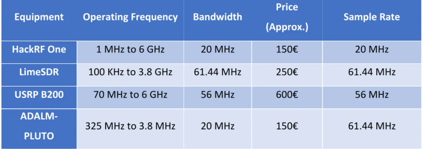
The HackRF One was chosen once it was the one with a better relationship between price, operating frequencies, bandwidth and samples rate when compared to its peers. A brief comparison between the most common RX/TX SDRs is made on Table 7:
Table 7 - Comparison between SDRs
Equipment Operating Frequency Bandwidth Price
(Approx.) Sample Rate
HackRF One 1 MHz to 6 GHz 20 MHz 150€ 20 MHz
LimeSDR 100 KHz to 3.8 GHz 61.44 MHz 250€ 61.44 MHz
USRP B200 70 MHz to 6 GHz 56 MHz 600€ 56 MHz
23
3.1.3 GNU Radio
According to the definition on [41], “GNU Radio is a free & open-source software development toolkit that provides signal processing blocks to implement software radios. It can be used with readily available low-cost external RF hardware to create software-defined radios, or without hardware in a simulation-like environment. It is widely used in research, industry, academia, government, and hobbyist environments to support both wireless communications research and real-world radio systems.”
GNU Radio provides a useful tool called GNU Radio Companion. The Companion is a tool that allows the user to build flow graphs through a series of pre-made blocks, providing a way to create its programs in an intuitive way, with a graphical interface, for rapid prototyping. Because the Companion’s blocks generate a python script, it’s possible to program the blocks with python code lines, allowing the blocks to have a greater interaction between them, making it a powerful signal processing tool.
3.1.4 Raspberry Pi
To run the previous programs, the HackRF must be connected to a computer containing the programs and the necessary dependencies. In order to implement them on an autonomous vehicle, especially on an Unmanned Aerial Vehicle (UAV), the computer must be small and light without losing the processing capacity to run the programs.
To accomplish this, the found solution was to use a Raspberry Pi. The Raspberry Pi is a low-cost single-board computer built by the Raspberry Pi Foundation [42] which, according to the latter, is intended for code learning and to build electronics projects. The used model is the Raspberry Pi 3B+ with a 1 GB RAM, 4 USB ports and 1.4 GHz 64-bit CPU. Its storage is guaranteed by a 32 GB SD card with the Raspbian Operating System installed [43].
The Raspberry was chosen because it was the one with a better relationship between price, CPU, RAM and size of the online community, when compared to its peers. A brief comparison between the most common single board computers is made on Table 8:
24
Table 8 - Comparison between single board computers
Equipment Price
(Approx.) CPU RAM Online Community
Raspberry Pi 3B+ 35€ ARM Cortex-A53 1 GB Big
Banana Pi 35€ ARM Cortex-A7 1 GB Medium
ODROID-XU4 70€ ARM Cortex-A15 2GB Medium
3.2 Software Development
To create the jamming and spoofing capacities that compose the EW package, GNU Radio programs were developed. All programs were divided in two parts: a client and a server. The server is the part that runs on the autonomous vehicle and the client is the part that is on the Ground Control Station (GCS).
3.2.1 AIS Jammer:
The AIS Jammer is a program composed by a set of blocks with the capacity of jamming an AIS signal reducing the situational awareness for the jammed unit. The blocks provide the user the options of choosing the bandwidth of the jamming signal adapted to the AIS and the IF and RF gains. The AIS Jammer was built in GNU Radio with the blocks on Figures 8 and 9:
25
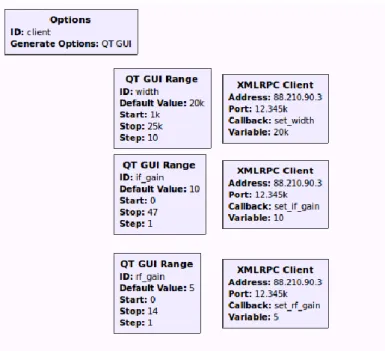
Client:
Figure 8 - AIS Jammer Client Block Diagram
The used blocks were:
• QT GUI Range ID: “width” – This block is a slider which gives the user the option of controlling the width of the jamming signal by changing the cut-off frequency of the low pass filter. It has a minimum value of 1 kHz, a maximum value of 25 kHz and a default value of 20 kHz.
• QT GUI Range ID: “if_gain” and “rf_gain” – These blocks are sliders that are used to control the intermediate frequency (IF) gain and the RF gain. The IF gain slider has a minimum of 0 dB, a maximum of 47 dB (HackRF limit) and a default of 10dB and the RF slider has a minimum of 0 dB, a maximum of 14 dB (HackRF limit) and a default of 5 dB.
• XMLRPC Client – Block that makes the connection between the Server and Client using the XML-RPC protocol. Each variable has a dedicated XMLRPC block which has as input the Internet Protocol (IP) address and port of the machine where the Server is.
26
Server:
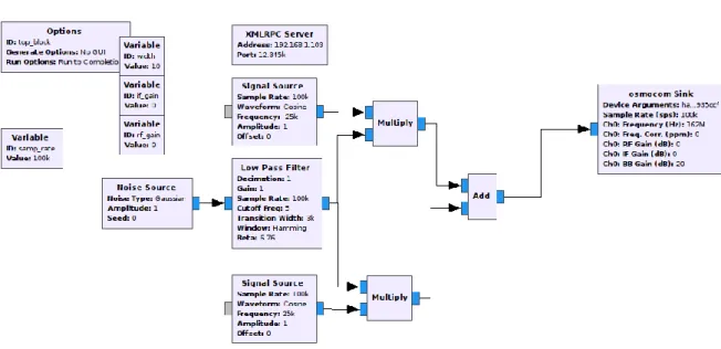
Figure 9 - AIS Jammer Server Block Diagram
The used blocks were:
• Variable ID: “samp_rate” – Variable containing the sample rate used by the other blocks. It has a value of 100 kHz which is enough to cover both AIS Channels. • Variable ID: “if_gain” – Variable that receives the desired value to the IF gain. • Variable ID: “rf_gain” – Variable that receives the desired value to the RF gain. • Variable ID: “width” – Variable that receives the desired value to the bandwidth
of the jamming signal.
• XMLRPC Server - Block that makes the connection between the Server and Client using the XML-RPC protocol. The XMLRPC block is programmed with the Internet Protocol (IP) address and port of the Server.
• Noise Source – Gaussian noise source which will produce the jamming signal. • Low Pass Filter – Low pass filter with a cut-off frequency equal to “width/2” and
a transition width of 3 kHz. This block is used to filter the noise to a bandwidth equal to the bandwidth of each AIS channel. The graph of the low pass filter is shown on Figure 10:
• Signal Source – Two cosine signal sources, with a frequency of -25 kHz and 25 kHz. These frequencies are used because the two AIS channels are located at 162 MHz ± 25kHz. When they are multiplied by the signal generated by the low pass
27 filter, they produce two waves with a bandwidth equal to “width/2” centred at ± 25 kHz. The equation that represents the generated signal is the following, with A being the amplitude and f the difference between the channel frequencies and 162MHz:
𝑦(𝑡) = 𝐴 cos(2𝜋 ± 𝑓) (1) • Add – Block used to add the ± 25 kHz signals.
• Osmocom Sink – Block that sends the information to the HackRF and shifts the signals to the desired frequency. In this case, it’s set to 162 MHz, the AIS frequency. It also deals with the IF and RF gains provided by the sliders.
Figure 10 shows the information sent by the “Add” block to the HackRF with the “width” variable with the value 10.
Figure 10 - Information sent to the HackRF by the “Add” Block
3.2.2 Free Jammer
The Free Jammer is a program with the objective of generating a jamming signal in an arbitrary frequency. The user can choose the centre frequency of the jammer, between 30 MHz and 6 GHz (operating frequencies of the HackRF), the bandwidth of the jamming signal and control the IF and RF gains. The Free Jammer was built in GNU Radio with the blocks on Figures 11 and 12:
28
Client:
Figure 11 - Free Jammer Client Block Diagram
The used blocks were:
• Variable ID: “samp_rate” – Used for tests.
• QT GUI Entry ID: “freq” – Block that generates a text box for the user to introduce the desired centre frequency.
• QT GUI Range ID: “bw” – Slider to control the bandwidth of the emitted signal. It has a minimum of 1 Hz, a maximum of 2 MHz (might be altered according to the purpose of the jammer) and a default of 100 kHz.
• XMLRPC Client; QT GUI Range ID: “if_gain” and “rf_gain” – Same function as in 3.2.1.1
29
Server:
Figure 12 - Free Jammer Server Block Diagram
• Variables – Variables that receive the values from the client through the XMLRPC blocks.
• Multiply – Block used to multiply the signal from the “Signal Source” and the “Low Pass Filter”.
• Low Pass Filter – Same function as in 3.2.1.2 with a cut-off frequency of “bandwidth/2”.
• XMLRPC Server; Noise Source; Signal Source – Same function as in 3.2.1.2 • Osmocom sink – Same function as in 3.2.1.2 with a variable centre frequency
defined by the “bw” variable.
3.2.3 Wi-Fi Jammer
The Wi-Fi Jammer is a program with the capacity of jamming signals that operate in the same frequency as the Wi-Fi. The user can choose which channel does he wish to jam in the 2.4GHz band and in the 5GHz band. The Wi-Fi Jammer was built with the blocks on Figures 13 and 14:
30
Client:
Figure 13 - Wi-Fi Jammer Client Block Diagram
The used blocks were:
• QT GUI Chooser ID: “wifi” – Block that allows the user to choose which Wi-Fi channel does he want to jam.
• XMLRPC Client; QT GUI Range ID: “if_gain” and “rf_gain” – Same function as in 3.1.1.1
Server:
31 The used blocks were:
• Variables – Variables that receive the values from the client through the XMLRPC blocks.
• Multiply – Block used to multiply the signal from the “Signal Source” and the “Low Pass Filter”.
• Low Pass Filter – Same function as in 3.2.1.2, with a cut-off frequency of 500kHz. • XMLRPC Server; Noise Source; Signal Source – Same function as in 3.2.1.2. • Osmocom sink – Same function as in 3.2.1.2, with a variable centre frequency
defined by the “wifi” variable.
3.2.4 WI-FI Jammer All Band
The Wi-Fi Jammer All Band is a program designed to jam all the 2.4GHz Wi-Fi band. It only requires a Server because there are no changeable parameters, as shown on Figure 15.
Server
Figure 15 - Wi-Fi Jammer All Band Server Block Diagram
The Wi-Fi Jammer All Band Server is composed by the following blocks:
• Variable ID: “sweep_time” – Variables that defines a value for the sweep time on the “Function Probe” block.
32 • Variables ID: “center_freq_max” and “center_freq_min” – Variables created to
indicate the amplitude of the signal to be probed.
• Signal Source and Probe Signal Vector – The first block creates a cosine wave that is then probed by the Probe Signal Vector block.
• Function Probe – Receives the vector from the “Probe Signal Vector” block and creates a function with that data.
• Signal Source and Osmocom Sink – Receive the signal from the “Function Probe” block and transmits it to the HackRF.
3.2.5 GNSS Jammer
The GNSS Jammer is a program designed to jam three GNSSs: GPS, GLONASS and GALILEU. The GNSS Jammer has the block diagrams shown in Figures 16 and 17:
Client
Figure 16 - GNSS Jammer Client Block Diagram
The used blocks were:
• Variable ID: “gps_freql1”, “gps_freql2”, “glonass” and “galileu” – Variables that define the centre frequency of the GPS, GLONASS and Galileo systems.
33 • QT GUI Chooser ID: “gnss” – Block that generates buttons that allow the user to
choose which GNSS does he wish to jam.
• QT GUI Chooser ID: “n” – Block that creates a list of possible GLONASS channels to jam ( -7 to 6).
• XMLRPC Client; QT GUI Range ID: “if_gain” and “rf_gain” – Same function as in 3.2.1.1
Server
Figure 17 - GNSS Jammer Server Block Diagram
The used blocks were:
• Variables – Variables that receive the values from the client through the XMLRPC blocks.
• Multiply – Block used to multiply the signal from the “Signal Source” and the “Low Pass Filter”.
• XMLRPC Server; Noise Source; Signal Source; Low Pass Filter – Same function as in 3.2.1.2.
• Osmocom sink – Same function as in 3.2.1.2 with a variable centre frequency defined by the “gnss” variable.
34
3.2.6 AIS Spoofer
The AIS Spoofer is a program that has the capacity of creating AIS contacts. The AIS sentences on the server were built with the codes provided in [44] for AIVDM/AIVDO protocol decoding and by the US Coast Guard on [45] and the AIS Frame Builder Block used was created by Marco Balduzzi [46]. The AIS Spoofer has the following block diagrams (Figures 18 and 19):
Client
Figure 18 - AIS Spoofer Client Block Diagram
The used blocks were:
• WX GUI Text Box ID: “mmsi” – Block that receives the MMSI.
• WX GUI Chooser ID: “NAVSTAT” – Block that receives the navigational status and converts it into a number for the construction of the final message. The available navigational statuses are:
35 o At anchor;
o Not Under command; o Restricted manoeuvrability; o Moored;
o Aground;
o Engaged in fishing; o Under way sailing; o Not defined.
• WX GUI Text Box ID: “SOG” – Receives the speed over ground value in knots. • WX GUI Chooser ID: “tipe” – Receives the type of ship and converts it into a
number. The available types of ships are: o Not Available;
o Wing in ground; o Fishing;
o Towing;
o Dredging or underwater ops; o Diving ops;
o Military ops; o Sailing;
o Pleasure Craft; o Pilot Vessel;
o Search and Rescue vessel; o Tug;
o Law Enforcement; o Medical Transport;
o Non-combatant ship according to RR Resolution No. 18; o Passenger;
o Cargo; o Tanker; o Other Type.
36 • WX GUI Text Box ID: “width” – Receives the width of the ship value in meters. • WX GUI Notebook ID: “notebook” – Creates an interface to accommodate all the
text boxes and choosers.
• WX GUI Text Box ID: “Long” – Receives the longitude value for the position of the ship
• WX GUI Text Box ID: “Lat” – Receives the latitude value for the position of the ship
• WX GUI Text Box ID: “COG” – Receives the course over ground value in degrees. • WX GUI Text Box ID: “cs” – Receives the callsign of the ship.
• WX GUI Text Box ID: “name” – Receives the name of the ship.
• WX GUI Chooser ID: “channel_select” – Allows the user to choose the AIS channel and which message does he wants to send. The available options are: Dynamic - CHA, Dynamic - CHB, Dynamic - Both, Static – A and Static – B.
• XMLRPC Client – Same function as in 3.2.1.1.
37
Figure 19 - AIS Spoofer Server Block Diagram
The used blocks were:
• Variables ID: “mmsi”, “NAVSTAT”, “SOG”, “Long”, “Lat”, “COG”, “name”, “cs”, “channel_select”, “tipe”, “length” and “width” –Variables that receive the values from the client through the XMLRPC Server block.
• Variable ID: “Dynamic” – Builds the Dynamic AIS message (type 1), making it ready to introduce in the AIS Frame Builder. The message is built according to Table 9:
Table 9 - AIS Dynamic Message Sentence
Nº Bits Description Message Part
38 2 Repeat Indicator 00 30 MMSI "{0:b}".format(mmsi).rjust(30,'0') 4 Navigation Status "{0:b}".format(NAVSTAT).rjust(4,'0') 8 Rate of Turn 10000000 10 SOG "{0:b}".format(SOG*10).rjust(10,'0') 1 Position Accuracy 1 28 Longitude '{0:b}'.format(int(round(Long*600000))& 0b1111111111111111111111111111).rjust(28,'0') 27 Latitude '{0:b}'.format(int(round(Lat*600000))& 0b111111111111111111111111111).rjust(27,'0') 12 COG "{0:b}".format(COG).rjust(12,'0') 9 True Heading 111111111 6 Time Stamp 101000 2 Manoeuvre Indicator 00 3 Spare 000 1 RAIM Flag 1 19 Radio Status 0010100000111110011
• Variable ID: “Part A” - Builds the Static AIS message (type 24), making it ready to introduce in the AIS Frame Builder. The type 24 AIS message is divided in two parts: A and B. The part A message is built according to Table 10:
Table 10 - AIS Static Part A Message Sentence
Nº Bits Description Message Part
6 Message Type 011000
39 30 MMSI "{0:b}".format(mmsi).rjust(30,'0')
2 Part Number 00
120 Vessel Name namebin+('0'*(156-6-2-30-2-len(name)))
• Variable ID: “Part B” – Part B of the static type 24 AIS Message. The part B message is built according to Table 11. The dimensions present on the static type 24 AIS message are the distances from the AIS antenna. Here, it’s considered that the antenna is in the middle of the ship.
Table 11 - AIS Static Part B Message Sentence
Nº Bits Description Message Part
6 Message Type 011000
2 Repeat Indicator 00
30 MMSI "{0:b}".format(mmsi).rjust(30,'0')
2 Part Number 01
8 Ship Type '{0:b}'.format(tipe).rjust(8,'0')
18 Vendor ID 000000000000000000000000000000000000000000
42 Callsign csbin (Variable)
9 Dimension to Bow '{0:b}'.format(lenght/2).rjust(9,'0') 9 Dimension to Stern '{0:b}'.format(lenght/2).rjust(9,'0') 6 Dimension to Port '{0:b}'.format(width/2).rjust(6,'0')
6 Dimension to
Starboard1 '{0:b}'.format(width/2).rjust(6,'0')
6 Spare 000000
• Variable ID: “Vocabolary” – List of 6-bit ASCII characters used in AIS sentences. • Variable ID: “nametest” – Creates a 20-character sentence containing the name
of the ship and, if the name isn’t 20 characters long, it replaces the empty spaces with the “@” character. The “@” is the first character in the 6-bit ASCII
40 vocabulary (000000). That’s why it’s the character replacing empty spaces. The code used is: name+"@"*(19-len(name)).
• Variable ID: “letter(number)” – Variable that reads the character on the “nametest” variable. There is one “letter” variable for each character. The code used is: nametest[number].
• Variable ID: “namebin” – It replaces each character in the “letter” variables for its 6-bit ASCII code equivalent. The code used is:
'{0:b}'.format(vocabolary.find(letter0)).rjust(6, '0') + '{0:b}'.format(vocabolary.find(letter1)).rjust(6, '0') + …
• Variable ID: “cslenght” – Same as the “nametest” variable but applied to the callsign.
• Variable ID: “csbin” – Same as the “namebin” variable but applied to the callsign. • Variable ID: “amp” – Variable used to define the amplitude of the signals. • AIS Frame Builder – Block that transforms the sentences from the Dynamic, Part
A and Part B variables into an AIS Frame.
• GMSK Mod – Block that modulates the AIS Frame using Gaussian Minimum Shift Key modulation.
• Selector – Selects what signal to send to the “osmocom Sink” block.
• Signal Source, osmocom Sink, Multiply and Add – Same function as in 3.2.1.2 and 3.2.2.2.
3.2.7 Remote Control
To implement the EW package and running the programs in an autonomous vehicle, it was necessary to create a way of controlling them remotely. In order to do that, two external programs had to be created. These programs (programmed in Python), the “Client” and the “Server” are in Appendix A and B, with the explained script and steps.
The “Client” is the program that runs on the GCS and is responsible for sending the messages and commands to the UxS and to open the interface programs on the GCS. It allows the user to input the IP address and port for communicating with the UxS. After introducing these parameters, the program asks the user what program does he which
41 to initiate, being the available programs the AIS Jammer, the AIS Spoofer, the Free Jammer, the GNSS Jammer, the WiFi Jammer and the WiFi Jammer All Band.
The “Server” is the program that runs in the UxS and it deals with the commands received from the “Client” and starts the previously mentioned programs on the Raspberry Pi. Also, the “Server” sends messages to the GCS to provide confirmation and status information to the user.
With this, the system ends up with the following architecture (Figure 20 and 21):
Figure 20 - EW Package Physical Architecture
USB Remote Control
Server Server Programs
Raspberry Pi HackRF One
Remote Control Client
Client Programs
42 Remote Control Server Server Programs AIS Jammer AIS Spoofer WiFi Jammers Free Jammer GNSS Jammer Remote Control Client Client Programs AIS Jammer AIS Spoofer WiFi Jammers Free Jammer GNSS Jammer UDP XMLRPC Block
43
4 Experiments and Results
In order to prove the effectiveness and the applicability of the Jammer, some tests were made. In this chapter, those tests are presented.
4.1 Portuguese Naval Academy Test
On the 14th of January 2019, a test was made at the Portuguese Naval Academy. The objective was to test if the WiFi Jammer was effective against an UAV commercial off the shelf (COTS). The UAV used for this test was a “Parrot Bebop 2” which is controlled via an app on a mobile phone along with the “Parrot Skycontroller 2” for increased range with a transmission power of 24dBm and an antenna gain of 5dBi. The UAV’s control signal and video link frequency are in the 2.4 GHz band. Specifically, for this test, WiFi channel 11 (2.462 GHz) was chosen in order to reduce the interference to other working networks, after an analysis has been made to the surrounding environment.
On the Jammer side, the used program was the WiFi Jammer, running on a laptop along with the HackRF, a 1W WiFi signal amplifier and a 7dBi WiFi antenna. Once the used antenna was omnidirectional, a home-made reflector was made in order to increase its directivity. With a spectrum analyser, a test was made in order to detect the power that the WiFi amplifier was really emmiting. The registered value 42dbm above the noise level. The power amplifier was 1 meter away from the antenna of the spectrum analyser. In Figure 22, a screenshot of the spectrum analyser is shown:
44 According to the Wireless-Nets [47], the minimum signal to noise ratio (SNR) for a wireless communication to be able to be established and to be stable is 10 dB. With this, in order to jam the signal between the remote controller and the UAV if they’re 1 meter apart (SNR=53dB) [48], the jammer to signal ratio must be approximately -43dB. So, in order to determine the maximum theoretical jamming distance, the Friis equation is applied:
𝐽
𝑆
=
𝑃𝐽𝐺𝐽𝐺𝑅𝜆2 (4𝜋𝑑𝐽)2 𝑃𝑇𝐺𝑇𝐺𝑅𝜆2 (4𝜋𝑑𝑠)2 (1)Simplifying and converting to dB: 𝐽
𝑆
= 𝑃
𝐽+ 𝐺
𝐽− 𝑃
𝑇− 𝐺
𝑇+ 20 log 𝑑
𝑆− 20 log 𝑑
𝐽(2)
Being:
• J the jammer signal power at intended receiver (dB) • S the transmitter signal power at intended receiver (dB) • PJ the jammer signal output power (dBW)
• PT the transmitter output power (dBW) • GJ the jammer antenna gain (dBi) • GT the transmitter antenna gain (dBi)
• dJ the distance from the jammer to the receiver (m) • dS the distance from the transmitter to the receiver (m) Being dJ the desired value, the final equation is:
𝑑
𝐽= 10
𝑃𝐽+𝐺𝐽−𝑃𝑇−𝐺𝑇+20 log(𝑑𝑆)− 𝐽 𝑆20 (3) After substituting the values, the obtained theoretical value for the maximum range of the jammer was 376 meters.
45
Figure 23 - Jammer set on the Naval Academy’s Test
To do the test, the UAV and controller were both with the operator within a maximum distance of 1 meter. After turning on the Jammer, the operator started to move away from the jammer in a straight line. The stopping point for the operator would be either when the Jammer stopped being effective or when he reached the limit of the Academy’s perimeter.
Figure 24 shows the points where the Jammer was and the point where the UAV and the remote controller was:
46
Figure 24 - Naval Academy's Jamming Test
The Jammer was effective until the operator reached the Academy’s perimeter, totalling an effective distance of 300 meters, with a free-space pathloss of 89.20dB, as described in the following equation, being d the distance in kilometres and f the frequency in MHz:
𝐹𝑆𝑃𝐿(𝑑𝐵) = 32.5 + 20 log 𝑑 + 20 log 𝑓 (2) Between the jammer and the UAS operator there were some obstacles, such as cars, trees and fences.
4.2 Portuguese Marines Base Test
Another test has been made during an EW exercise against UAVs COTS in the 17th of January 2019. This time, the test was done at the Portuguese Marines Base in the Lisbon Naval Base. The purpose of this exercise was to test the available capacities of the Portuguese Marines EW Unit against UAVs, using several techniques and equipment available on a portable container designed to be easily deployed and to assist amphibious operations.
47 To test the Wi-Fi Jammer, all the parameters of the exercise were similar to the ones in the Naval Academy’s Test. Figures 25 and 26 show the set of the Jammer and the points where the operator and the Jammer were, respectively:
Figure 25 - Portuguese Marines container and Parrot Bepop 2
Figure 26 - Portuguese Marines Base Jamming Test
In this case, the jamming was also effective in the measured distance of 330 meters with a free-space pathloss of 90.70dB.
48
4.3 Lisbon Naval Base Test
On the 12th of February 2019, a test was made at the Lisbon Naval Base in order to determine how effective were the Portuguese Navy’s defences against UAS COTS and to determine if the Wi-Fi Jammer was effective against these threats on a more realistic scenario. The exercise’s report in presented on Appendix C.
The exercise was composed by a series of approaches with UAS COTS to two ships (NRP António Enes and NRP Vasco da Gama) in order to verify the crew’s procedures to the presence of unauthorized UAS flying on the Naval Base perimeter. To do this, several approaches were made at different altitudes and speeds with two types of UAVs: a fixed-wing and a rotary-fixed-wing. After this, a jamming test was made to test the performance of this defensive measure against an UAS approaching at its maximum velocity.
The flight plan of the fixed-wing UAV during the exercise is presented on Figure 27:
Figure 27 - Naval Base Test Fixed-Wing UAV Flight Plan
The overall results of the test regarding the use of the Wi-Fi Jammer were good. The jammer was capable of making the UAV to stop on a stationary flight, heavily reducing the threat that it posed.
![Figure 1 - Overview of EW [4]](https://thumb-eu.123doks.com/thumbv2/123dok_br/15467643.1033151/25.892.124.814.598.967/figure-overview-of-ew.webp)
![Figure 2 - EM Operations Concept [10]](https://thumb-eu.123doks.com/thumbv2/123dok_br/15467643.1033151/26.892.133.760.301.629/figure-em-operations-concept.webp)
![Figure 3 - EM Actions and Effects [14]](https://thumb-eu.123doks.com/thumbv2/123dok_br/15467643.1033151/27.892.146.740.112.516/figure-em-actions-effects.webp)
![Figure 4 - Relationship between the several areas of EW [14]](https://thumb-eu.123doks.com/thumbv2/123dok_br/15467643.1033151/28.892.205.754.582.1003/figure-relationship-areas-ew.webp)
![Figure 5 - Five jammer spectral densities types [17]](https://thumb-eu.123doks.com/thumbv2/123dok_br/15467643.1033151/31.892.162.729.120.597/figure-five-jammer-spectral-densities-types.webp)
![Figure 6 - Comparison between a rectangular and a spread spectrum signal in the presence of a barrage jammer [18]](https://thumb-eu.123doks.com/thumbv2/123dok_br/15467643.1033151/32.892.175.712.118.548/figure-comparison-rectangular-spread-spectrum-signal-presence-barrage.webp)
![Figure 7 - Types of jammers by [12]](https://thumb-eu.123doks.com/thumbv2/123dok_br/15467643.1033151/33.892.133.775.521.1058/figure-types-of-jammers-by.webp)