Received May, 2nd, 2011, Revised September 19th, 2011, Accepted for publication September, 19th, 2011.
Copyright © 2011 Published by LPPM ITB, ISSN: 1978-3086, DOI: 10.5614/itbj.ict.2011.5.2.4
Architecture for the Secret-Key BC3 Cryptography
Algorithm
Arif Sasongko1, Hidayat2, Yusuf Kurniawan1 & Sarwono Sutikno1
1
Electrical Engineering, School of Electrical Engineering and Informatics, Institut Teknologi Bandung, Bandung, Indonesia
2
Computer Engineering, UNIKOM, Bandung, Indonesia
Email: 1asasongko,yusufk,[email protected], 2 [email protected]
Abstract. Cryptography is a very important aspect in data security. The focus of research in this field is shifting from merely security aspect to consider as well the implementation aspect. This paper aims to introduce BC3 algorithm with focus on its hardware implementation. It proposes an architecture for the hardware implementation for this algorithm. BC3 algorithm is a secret-key cryptography algorithm developed with two considerations: robustness and implementation efficiency. This algorithm has been implemented on software and has good performance compared to AES algorithm. BC3 is improvement of BC2 and AE cryptographic algorithm and it is expected to have the same level of robustness and to gain competitive advantages in the implementation aspect. The development of the architecture gives much attention on (1) resource sharing and (2) having single clock for each round. It exploits regularity of the algorithm. This architecture is then implemented on an FPGA. This implementation is three times smaller area than AES, but about five times faster. Furthermore, this BC3 hardware implementation has better performance compared to BC3 software both in key expansion stage and randomizing stage. For the future, the security of this implementation must be reviewed especially against side channel attack.
Keywords: BC3; FPGA; hardware implementation; symmetric key cryptography.
1
Introduction
The encryption algorithms are classified into two types: secret-key and public-key. The secret-key (symmetric key) algorithm uses same key for encryption and decryption so this key must be kept secret. It is shared exclusively between sender and receiver to protect the data in communication. Conversely, the public-key algorithm uses different key for encryption and decryption [2]. Secret key cryptography has more efficient implementation than public key cryptography. BC3 [3] is one of the secret-key algorithms [4]. This algorithm is result of enhancement of BC2 algorithm [5] and AE3 algorithm [6]. The security of BC2 and AE3 has been investigated quiet intensively. This new BC3 algorithm is modification of the BC2 algorithm especially for the reason of implementation efficiency. It is believed that the security aspect is not too different from BC2. It is developed by bearing in mind two considerations: projected security (robustness to attack) and efficient implementation. As most of secret key algorithm, for example AES, this algorithm can be divided into two stages: key expansion, and randomizing. The key expansion stage is performed to generate several subkeys from the main key (key master). The next stage is randomizing step wherein the data (plain text/chipper text) is manipulated using the subkeys to hide the information.
This algorithm has advantages compared to AES in two aspects. In the security aspect, the subkeys expansion in the BC3 are more secure than AES since the main key is extremely difficult to find even when the subkeys are found. In many cryptanalysis, for example differential and linear attacks, attacker try to find the subkeys before finding master key [7]. So without knowing the subkeys, attacker can not get master key. If the master key cannot be found from subkeys, attacker can never find the master key. The other advantage is that the key-expansion speed is much higher. The software implementation shows significant performance advantage compared to AES [5]. The hardware implementation of this algorithm is investigated in the work described in this paper.
The hardware implementation is very important from point of view performance and security, especially as countermeasure against timing attack[8], to avoid the key being left on the memory, and to save the computer memory. Therefore, we work to find architecture for BC3 hardware implementation which is efficient, especially number of gates or area since the speed of hardware implementation is certainly much higher than software implementation in several orders of magnitude.
with AES [4]. The security analysis is always the most important aspect in cryptography but it is not the subject of this particular paper. Moreover, it is believed that the security is not too difference from BC2, and it will be treated on other papers.
2
BC3 Algorithm and the Software Implementation
The BC3 algorithm is improvement of BC2 [5] and AE3 [10]. The characteristics of BC3 are quiet similar with AES and Camellia [11]. It is developed with two considerations: projected/measured securities/robustness and implementation efficiency. It means that this algorithm is designed to survive against various attacks or crypto analysis. At the same time, it is also designed to be implemented at various platforms efficiently and fast.
As described above, this algorithm can be divided into two stages: key expansion (or key schedule) and randomizing. Key expansion stage is performed to generate subkeys. The randomizing stage is performed to manipulate the data using the subkeys. The randomizing stage makes the plaintext encrypted or the cipher text decrypted. This randomizing stage consists of 11 rounds. In every round, a function F is applied to the data (plain text, chipper text or intermediate data produced by the previous round). This function uses different subkeys to manipulate the plain text in each round. This function is extremely difficult to be inverted without knowing the subkeys. The detail of this function is described later in Section 2.1.
The main features of BC3 algorithm are:
1. The width of input and output block is 64 bits (plain text and chipper text).
2. The main key length is 128 bits.
3. Key expansion is done in two steps (by six regular rounds and several logic
operations). Regular round is the same F function used in the randomizing stage.
4. Randomizing stages in encryption and decryption processes are applied in eleven regular rounds. Each regular round consists of the same F function. 5. In addition to the regular round, special function FA and FA-1 are used in
every encryption and decryption process.
3
Encryption and Decryption (Randomizing) Stage
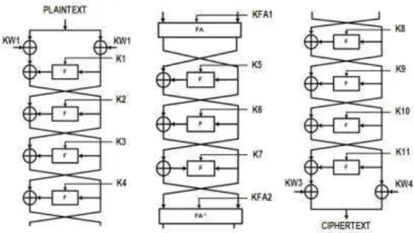
BC3 uses Feistel Network [2], so it encrypts and decrypts data with the same algorithm. This Feistel network is used in many algorithms such as DES, BLOWFISH, CAMELIA and Lucifer. Figure 1 shows the randomizing stage of encryption and decryption in BC3 algorithm. It uses eleven F functions and two
special functions called FA and FA-1 functions. In each round, the key which is
used to compute the F functions is different. These keys are called K1 for 1st round, K2 for the 2nd round, K3 for the 3rd round, K4, K5…K11. The FA and FA-1 functions are inserted before the 5th round and 8th round respectively. Moreover, subkeys: KW1, KW2, KW3, and KW4 are XORed with the data before the first round and after the last round. All of these subkeys are previously derived from the main key in the key expansion stages.
Figure 1 Randomizing stage of BC3 algorithm.
4
The F Function
The F function has two input. Each of them is 32 bits. This first input is either first half part of plaintext (in the first round of encripting process), half part of ciphertext (in the first round of decripting process), or data/output from previous
round/function. The second input is a subkey. The first input is represented by x
with 32-bits, the second input is K and output is represented by y with 32-bits in the following formula:
y = P(S[x]) K (1)
where:
P is operation of polynomial matrix multiplication;
S is operation of subtitution to x0,x1,x2,x3 inputs. S operation is done to every byte inputs;
K is sub keys k0,k1,k2,k3.
5
Substitution Box (s-box)
The S box is used in the S operation (subtitution). In this operation, each byte in the input vector is replaced by the byte from the S-box. S-box uses data in lookup table for substitution. The S-box of BC3 use a function that has properties almost similar to inversion function f(x) = x-1 in finite field
F
28. The linear/affine operation was added to this function to block algebraic attack [12]. This inversion function is chosen because it has excellent properties to hamper linear and differential attack. Following data S-box (in hexadesimal):BB 8B 9E DF 42 D8 F7 1F 52 D7 26 80 3E 20 17 5B F1 94 5E EE 78 91 7A 3C 62 53 24 F6 C2 97 E3 8D C4 FC 5F AD 40 2B A4 16 4C 50 BC 90 CA 60 96 50 81 BA 4E 10 C0 D5 49 C3 48 3D F0 B0 DE 76 DB F4 E6 CD 56 ED 6C F8 B6 C0 36 82 2E 7C DA 4A 92 DD 7F D4 99 B8 71 28 E9 33 AC 68 66 9F 1B 7D 88 00 A8 43 C1 1C 34 FD 59 8F CF D9 F0 C5 BD 46 31 14 1E F3 C6 58 3B 87 E5 6E 6F DC A9 B4 21 5D 30 39 9D CC 6B 23 D0 65 98 9A 73 77 7B 69 70 D0 37 64 EA 57 E1 EB 8A CE E0 F5 4D E4 5C 45 54 AB 83 9C 8E 2F 40 74 CB 70 55 2D 86 AA B3 A3 29 EC 51 E0 FB 8C E2 D6 12 E8 10 A5 A0 D2 EF 9B 93 11 35 D3 1D 79 1A B5 25 18 B7 AF 2C 4F FF A2 C8 13 22 60 E7 BF 44 3A C7 41 BE D1 15 FA 6A 67 95 80 B2 A1 19 AE 4B 7E C9 FE 85 B0 38 5A 27 A0 89 47 84 75 B1 A6 3F 30 20 63 72 F2 A7 2A F9 61 32 6D B9 90
The followings are examples how the s-box is used: if s-box input is 00 then
it’s output is BBx , if s-box input is 01 then it’s output is 8Bx, etc.
6
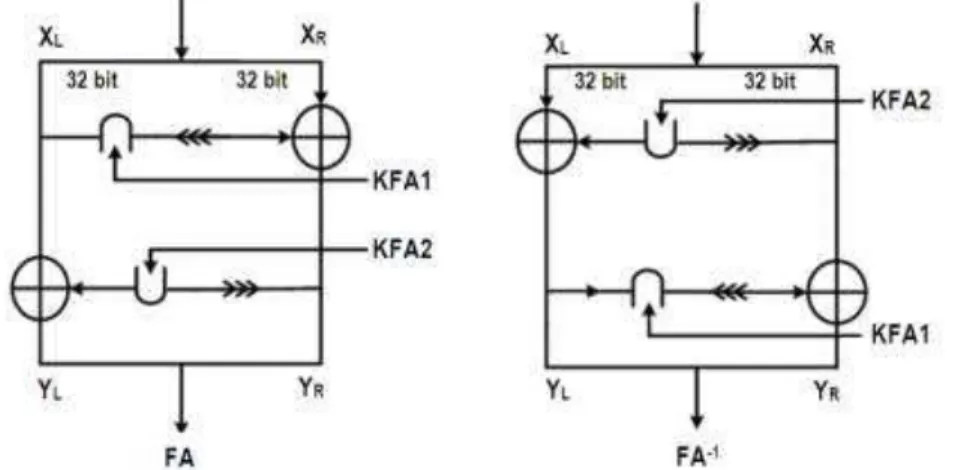
FA and FA
-1 FunctionThe other functions used in the randomizing stages are FA and FA-1. FA function is applied before the F function in the 5th round, FA-1 function is applied before the F function in the 8th round. FA function is defined as follow:
YR = ((XL KFA1) <<<1 ) XR
where:
>>>1 is shifts right 1 bit
<<<1 is shifts left 1 bit
is AND logic operator/intersection
is OR logic operator/union
FA-1 is invers of FA. So, it is defined as:
XL = YL ((YR>>>1) KFA2)
XR = YR ((XL KFA1) <<<1) (3)
Figure 2 illustrates FA and FA-1 functions.
Figure 2 Special functions: FA and FA-1.
7
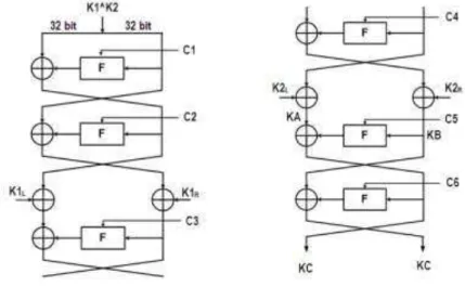
BC3 Key Expansion
main key K is used to generate KA, KB, KC and KD using process shown on Figure 3. The F function in this process is the same as F function in the randomizing stage. C1, C2, C3, C4, C5, C6 are constants which are parts of BC3 algorithm. These constants are described later in this section.
Figure 3 Initial part of BC3 key schedule.
After first step of BC3 key-schedule is done, second step is performed to generate the subkeys: KW1, KW2, KW3, KW4, K1, K2, K3, K4, K5, K6, K7, K8, K9, K10, K11, KFA1, KFA2. The computation is described as follow:
KE = KA KB KC
KF = KA KB KD
KG = KF KE KA (4)
Then, the following computation is performed:
KW1 = KE KF KG K7 = K6 KW2 KFA1
KW2 = KF KG KD KFA2 = K1 K5 K6
K1 = KE KW2 KF K8 = C3 K3 K7
K2 = KE KF KW1 K9 = (K5 >>>1) K3
K3 = KW1 KW2 K2 K10 = K8 K4 K5
K4 = K1 KW2 K3 K11 = K3 K5 K6
KFA1= C1 KE K4 KW3 = K9 K4 K6
K6 = K1 K2 K5 (5)
The constants: C1, C2, C3, C4, C5 and C6 have the same size 32 bits. The
constants C1 and C2 are taken from √0.7 (after the zero point ....) which is
D62F 59FB D597 BEF1 (64 bit). The constants C3 and C4 are taken from
√0.8 (after the zero point ....) which is E4F9 2E2D FF6E C9AB. The constants
C3 and C4 are taken from √0.9 (after the zero point ....) which is F2DC E89B 636C B246. So the constant are:
C1 = D62F59FBx ; C2 = D597BEF1x
C3 = E4F92E2Dx ; C4 = FF6EC9ABx
C5 = F2DCE89Bx ; C6 = 636CB246x
The objectives of the utilization of these constants are to get random keys and to show that there is not any backdoor on this algorithm.
8
BC3 Software Implementation
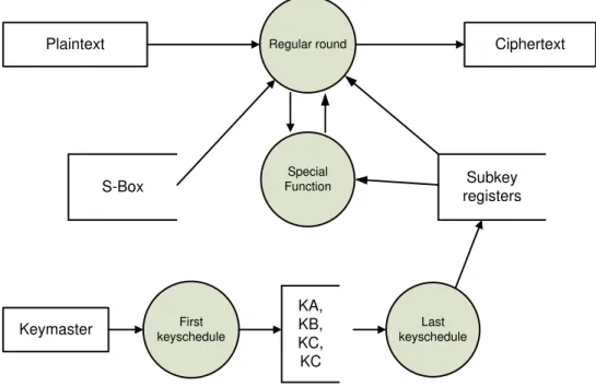
The source code of BC3 software implementation is written in C language [3]. This algorithm is constructed in 1150 lines code. The key schedule stage and randomizing stage take 0.7731 us and 0.71865 us respectively on PC with 1.2 GHz AMD Duron Processor. This result is better than AES [5]. Figure 4 shows the data flow diagram of BC3 software.
This implementation is very fast because it does not have any multiple rotations in program. Multiple rotations of data can slow down the software implementation significantly. The implementation consists of Boolean logic, substitution, and single bit rotation. This software is developed in the way that can be ported in different platform, processor and OS. It is also easy to compare this implementation with CAMELIA [13] or AES [14].
Plaintext Regular round
Subkey registers S-Box
Ciphertext
Special Function
First keyschedule
Last keyschedule
KA, KB, KC, KC Keymaster
Figure 4 The 1st level DFD of BC3 software.
The case is almost similar for key expansion. One key expansion process for AES or Camellia is equivalent to two key expansions for BC3. The number on the figure has been multiplied by two for the BC3.
Table 1 Comparison of Software Implementation.
Algorithm Encryption Time for 128
millions bit (in second)
Key expansion time
AES 0.453 1.063
BC2 0.765 0.378
BC3 0.485 0.390
Camellia 1.187 1.172
Khazad 0.687 1.063
IDEA 2.235 1.523
The AES has slow key schedule because encryption setup process is different from decryption setup process. If CFB encryption mode is used, then AES Key
expansion is faster since it doesn’t need decryption and key expansion for
9
BC3 Hardware Implementation
The objective of this research is to propose BC3 architecture with very efficient area. The implementation with minimum area can be easily used as co-processor, as part of smartcard, or other embedded system, wherein this algorithm is typically used. It is targeted that for every block of data (64 bit), the hardware being designed must need less than 12 clocks to perform encryption/decryption. Thus, 200 MHz hardware implementation can have throughput up to1 Gbps. So, it will be able to be used in Gigabit Ethernet or T1 network.
On the BC3 algorithm, the same F function is used every round in both randomizing stage and first part of key expansion stage. Thus, it is very advantageous to have a single block capable to perform this function multiple times. In addition, it is very efficient also if this block can performed FA and
FA-1 Function. For this reason, we design this computing block to perform those
functions as efficient and flexible as possible and it is named Regular Round block. This block must be a combinational digital circuit. Therefore every round needs only one clock. This choice must be taken to ensure that 64 bit input can be treated in less than 12 clocks as the objective described above.
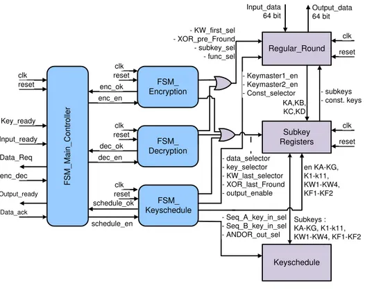
The other necessary computing block is a block to calculate the subkeys in the second part of key expansion: KW1, KW2, KW3, KW4, K1, K2, K3, K4, K5, K6, K7, K8, K9, K10, K11, KFA1, KFA2. This block takes Ka, Kb, Kc, and Kd as inputs and it is called Keyschedule block. Hence, the design has two computing blocks: regular round block and key schedule block. The regular round block is used in the randomizing and key scheduling stage. The key schedule block is used in the keyscheduling stage only.
Input_ready Key_ready enc_dec Data_Req enc_ok Data_ack Output_ready enc_en clk reset clk reset FSM_ Encryption FSM_ Decryption FSM_ Keyschedule F SM _Ma in _C o n tro lle r dec_ok dec_en clk reset schedule_ok schedule_en clk reset Regular_Round Subkey Registers Keyschedule - KW_first_sel - XOR_pre_Fround - subkey_sel - func_sel - data_selector - key_selector - KW_last_selector - XOR_last_Fround - output_enable en KA-KG, K1-k11, KW1-KW4, KF1-KF2 - Seq_A_key_in_sel - Seq_B_key_in_sel - ANDOR_out_sel Subkeys : KA-KG, K1-k11, KW1-KW4, KF1-KF2 KA,KB, KC,KD - subkeys - const. keys - Keymaster1_en - Keymaster2_en - Const_selector clk reset clk reset Input_data 64 bit Output_data 64 bit
Figure 5 BC3 algorithm architecture.
10
Control Block/FSM
The architecture above can be used for encryption and decryption. The operation of this architecture is defined in the FSM. For encryption process, the signal enc_dec must be driven high by the user (to set the mode to encryption). The operation of this architecture in this mode is as follow:
1. The main key must be entered through the input data port. The key ready signal must be driven high during this process to inform the main controller that a new key is fed to the system. Then, the main controller is sending
signal (schedule enable) to the FSM_Keyschedule so the
FSM_Keyschedule takes the control of the subkey registers block and the two computing blocks.
2. The FSM_Keyschedule controls the regular round block and uses it to
produce KA, KB, KC, and KD. The results are then stored in the register file (the subkey register block).
3. The FSM_Keyschedule controls the Keyschedule block and uses it to
then stored in the subkey registers block. The FSM_Keyschedule is then give the control back to FSM Main controller through the signal Schedule_ok. This signal informs the main controller that the key expansion process is completed.
4. The main controller sends the signal Data Req to tell the user that the system is ready to receive the data/plain text
5. When the user needs to encrypt data, the user must put the data to
input_data port and drives the signal Input_Ready high.
6. The main controller sends the signal Enc_Enable to tell the FSM Encryption
to starti its operation.
7. The Encryption FSM uses the regular round block to encrypt the data. It uses the proper subkeys which are stored in the Subkey registers as key in every round.
8. The output of encryption is then sent to Output_Data port and the control is
given back to FSM main controller.
9. The FSM Main controller sends the signal Output ready to the user.
10. The user can take the result and sends acknowledge to the system
11. The main FSM sends signal Input_Ready, so the user can put the next data
to be encrypted. The operation is loop back to step (4).
For the decryption mode, the operation is almost similar to decryption mode. The difference is that, at step 6, the main FSM send signal Dec_Enable to FSM Decryption instead of sending Enc_Enable to the FSM Encryption. Then, the FSM Encryption is taken the control of the Regular Round block. The signal enc_dec must be driven low by the user (to set the mode to decryption).
11
Regular_round Block
Regular_round block is used for round process in randomizing stage and first part of key-scheduling stage. Figure 7 shown the regular_round block. Basically, this block can be divided into two parts: input selector and F function. The input selector feed the block with the proper the input for each particular round. There are four possibilities of input: (1) from input port in the first round, (2) from previous round directly, (3) from previous round trough FA
function, or (4) from previous round trough FA-1 function. Figure 6 shows the
detail of this block.
Spec_Function FROUND SEL_2 SEL_2 SEL_2 SEL_2 Subkey_KW3 Subkey_KW4 XOR_last_Fround XOR_pre_Fround REGISTER Input_data Function_Sel SEL_ 1 1 SEL_ 6 SEL_2
Const_keyschedule Subkey_SK1 : SK11
subkey_sel Subkey_KF1 Subkey_KF2 Data_sel Keymaster1_en Output_data REG_1 SEL_ 4 SEL_ 4 Const_sel Key_sel Output_enable KW_last_selector 64 32 32 4 64 64 64 32 32
6 x 32
64 32 4 11 6 REG_2 32 32 Keymaster2_en 64
64 64 64
SEL_ 2 SEL_ 2 Subkey_KW2 Subkey_KW4 Subkey_KW1 Subkey_KW3 KW_first_sel Subkey_KW2 Subkey_KW1 clock reset SEL_4_64 32
Selection data from: -input_data, -keymaster -regular_round output, -FA or FA inverse
Regular_round process
FA and FA inverse process
Figure 6 The regular_round block.
12
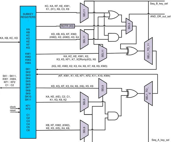
Key-schedule Block
SUBKEY REGISTERS : KA KB KC KD KE KF KG KW1 KW2 KW3 KW4 SK1 SK2 SK3 SK4 SK5 SK6 SK7 SK8 SK9 SK10 SK11 KF1 KF2 C1 C2 C3 C4 C5 C6 SEL1 1 SEL 1 1 SEL 9 SEL9 SEL 9 SEL1 _ T O_ 1 1 SEL1 1 SEL3 SEL1 _ T O_ 9
(KF, KW1, K1, K5, KF1, KF2, K11, K10, KW4)
KA, KE, (KE), C2, C1, K1, K3, K8, K2
KB, KF, KW2, (KW2), KE, K5, (K5), K4, K8,
KD, KG, KF, K3, K4, K6, (K6), K5, K9 KA, KC, KE, KW1, K2, K3, K5, KF1, K7, XORonly(K3), K6 KD, KB, KG, KF, KW2,
(KW2), K2, (KW2), K3, K4 KC, KA, KF, KE, KW1,
K1, (K1), K6, C3, K9
(KG, KE, KW2, K2, K3, K4, K6, K7, K8, K9, KW3) KA, KB, KC, KD
Seq_B_key_sel
Seq_A_key_sel AND_OR_out_sel
ROTR (K5)
SK1 : SK11, KW1 : KW4, KF1 : KF2
C1 : C2
clock reset
Figure 7 The keyschedule block.
13
Result of BC3 Hardware Implementation
The BC3 design is described in register transfer level by using VHDL. The number of files written for this design is 29 files. The design is then simulated using test vector. It is then compared with the software implementation and manual calculation to ensure the correctness.
faster FPGA or ASIC. The ASIC implementation can be faster in some orders of magnitude.
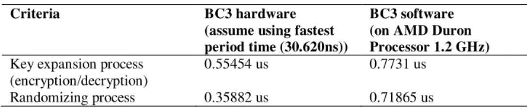
The comparisons of BC3 hardware with BC3 software is shown on Table 2.
Table 2 Comparison of BC3 implementation.
Criteria BC3 hardware
(assume using fastest period time (30.620ns))
BC3 software (on AMD Duron Processor 1.2 GHz)
Key expansion process (encryption/decryption)
0.55454 us 0.7731 us
Randomizing process 0.35882 us 0.71865 us
Table 2 show that key-scheduling and encryption/decryption processes on hardware is 0.55454 us and 0.35882 us, respectively. The key-scheduling and encryption/decryption processes on software are 0.7731 us and 0.71865 us, respectively. So, the time for key-scheduling and encryption/decryption processes on hardware implementation is faster than on previous software implementation.
The comparison of result BC3 hardware implementation with AES hardware [4] is shown on Table 3.
Table 3 Comparison of BC3 and AES.
Criteria BC3 (128 bits) AES (128 bits)
Logic elements 3,098 10,338
Randomizing process (encryption/decryption)
11 clock cycles 54 clock cycles
Key expansion 17 clock cycles 10 clock cycles
The result of area of BC3 algorithm is smaller than area of AES [4]. The main advantages come from: (1) flexible regular_round block so each round can be executed in single clock, (2) sharing the computation block when possible, (3) the design of BC3 algorithm which is very regular/homogenous .Actually, the ideas used in this architecture can be also to construct an architecture for AES.
14
Conclusions
implementation thanks to the exploitation of the regularity of the BC3 algorithm. Idea used in this architecture may be utilized also for other algorithm using Feistel network. For the future, the robustness of this implementation must be reviewed especially against side channel attack such as timing attack and power analysis attack.
References
[1] Goldreich, O., Foundations of Cryptography, Vol. I Basic Tools,
Cambridge, 2006
[2] Stallings, W., Cryptography and Network Security Principles and
Practices (4th ed.). New Jersey: Prentice Hall, 2005.
[3] Kurniawan, Y., Algoritma Enkripsi Indonesia BC3, http://ysfk2008.
wordpress.com, Accessed on November, 2011.
[4] Satoh, A., Morioka, S., Takano, K., & Munetoh, S., A Compact Rijndael
Hardware Architecture with S-Box Optimization, ASIACRYPT 2001, LNCS 2248. pp. 239-254, 2001.
[5] Kurniawan, Y., Suwandi, A., Mardianto, M. S., Supriana, I., Sutikno, S.
The New Block Cihper: BC2, International Journal of Network Security,
8(1), pp. 16-24, 2009.
[6] Kurniawan, Y., Analisis Sandi Diferensial AE3, Proceeding of Seminar
Nasional IC2007 BINUS University, Indonesia, 2007.
[7] Biryukov, A., Khovratovich, D. & Nikolić, I. , Distinguisher and
Related-Key Attack on the Full AES-256, Lecture Notes in Computer
Science, 5677/2009, Springer-Verlag, 2009
[8] Kocher, Paul C., Timing Attacks on Implementations of Diffie-Hellman,
RSA, DSS, and Other Systems, CRYPTO, 1996.
[9] ---, DBC2C20-Cyclone II Development Board, Altera, 2008
[10] Kurniawan, Y., Algoritma Enkripsi AE3 dan Analisis Sandi Linear,
Proceeding of Konferensi Nasional Sistem Informasi, Indonesia, 2008.
[11] Matsui, M., Nakajimi, J., A Description of Camellia Encryption
Algorithm, from http://www.ipa.go.jp/security/rfc/RFC3713EN.html, Accessed on Februari, 2009.
[12] Katz, J. & Lindell, Y., Introduction to Modern Cryptography, Chapman & Hall/CRC, 2008.
[13] Aoki, K., Ichikawa, T., Kanda, M., Matsui, M., Moriai, S., Nakajima, J.
& Tokita, T., Camellia : A 128-Bit Block Cipher Suitable for Multiple Platforms — Design and Analysis, Lecture Notes in Computer Science,
2012/2001, Springer-Verlag, 2001
[14] Bertoni, G., Breveglieri, L., Fragneto, P., Macchetti, M. & Marchesin, S.,
Efficient Software Implementation of AES on 32-Bit Platforms, Lecture