Abstract— The position error of a feed drive system is mostly caused by the thermal deformation of a ball screw shaft. A high- speed ball screw system can generate massive heat with greater thermal expansion produced, and consequently have a negative effect on the positioning accuracy. In this study, we applied the computational approach using the finite element method (FEM) to simulate the thermal expansion process for estimating the deformation of the ball screw system. In the numerical analysis, the deformation of the ball screw shaft and nut was modeled via a linear elasticity approach along with the assumption that the material was elastic, homogeneous, and isotropic. To emulate the reciprocating movements of the nut at a maximum speed of 40m/min corresponding to the screw shaft, we also employed a three-dimensional unsteady heat conduction equation with heat generation from the main sources including the ball screw shaft, nut and bearings as the heat transfer model to solve the detailed temperature distributions for determination of the temperature rises and axial thermal deformations in a ball screw shaft under operating situations. Calculations were conducted to evaluate the influence of cooling conditions on thermal deformations. The simulation results indicated that the positioning accuracy could be improved through effective cooling countermeasures implemented in the ball screw system.
Keywords— thermal deformation, ball screws, FEM
I. INTRODUCTION
The performance of a ball screw feed drive system in terms of speed, positioning accuracy and machine efficiency plays a very important role in product quality and yield in manufacturing industries primarily including machine tools, semi-conductors, optoelectronics, and so on. Considering a high-speed precision ball screw system, the occurrence of contact surfaces (such as the interfaces between the ball and nut grooves, the ball and screw grooves, and the bearing and shaft) produces contact friction at these junctions. The friction of the nut and ball bearings entails a sudden and violent heating of balls, and in turn results in the temperature rises of the ball screw, leading to mechanical micro-
Manuscript received February 25, 2013; revised March 6, 2013. This work was supported in part by the Ministry of Economic Affairs (MOEA), Taiwan, ROC under Grant 100-EC-17-A-05-S1-189.
A.S. Yang and S.Z. Cai are with the Department of Energy and Refrigerating Air- Conditioning Engineering, National Taipei University of Technology, Taipei, 106, Taiwan (phone: (886) 2-2771-2171 ext. 3523; fax: (886) 2-2731-4919; e-mail: [email protected]).
W.T. Wu is with the Department of Biomechatronics Engineering Nation Pingtung University of Science and Technology, Pingtung 912, Taiwan (e-mail: [email protected]).
W.H. Hsieh, S.H. Hsieh, T.C. Kuo and C.C. Wang are with the Department of Mechanical Engineering, and Advanced Institute of Manufacturing with High-tech Innovations, National Chung-Cheng University, Chiayi 621, Taiwan. (e-mail: [email protected])
Y.C. Hwang is with HIWIN Technologies Corp., Taichung 40852, Taiwan. (e-mail: [email protected]).
deformations and an overheating of the coolant. Such a temperature heating of ball screw could also cause significant thermal deformations deteriorating the ball screw system accuracy in mechatronics tools or instruments [1].
The development of fabrication technology for a variety of applications necessitates high-precision apparatuses for achieving remarkably delicate goods with high output [2]. As indicated by Bryan [3], the thermal induced error in precision parts has still been the key setback in the industry. Substantial efforts were done on the machine tools, thermal behavior and thermal error compensation on the spindles, bearings and ball screws, respectively. Ramesh et al. [4] and Chen [5] carried out the air-cutting experiments to reproduce the loads under actual-cutting situations. To adjust the thermal conditions of the machine tool, Li et al. [6] conducted the tests of varying spindle speed for controlling the loads. The performance of a twin-spindle rotary center was experimentally evaluated by Lo et al. [7] for particular operating settings. Afterward, Xu et al. [8] incorporated the contact resistance effect into a thermal model for simulation of machine tool bearings. Koda et al. [9] produced an automatic ball screw thermal error compensation system for enhancement of position accuracy. The frictional process from a high-speed ball screw system essentially released tremendous amounts of heat and results in the continuing temperature increase and thermal expansion, leading to deterioration of the positioning accuracy. In this investigation, we considered the heat generation from two bearings and the nut as the thermal loads with the prescribed heat flux values imposed on the inner surfaces of grooves between the bearings and nut of the ball screw system. The convection boundary conditions were also treated for solid surfaces exposed to the ambient air. A FEM-based thermal model was developed to resolve the temperature increase distribution and in turn to predict the thermal deformation of the ball screw. In addition, simulations were conducted to appraise the influence of cooling enhancement (through the replacement a solid ball screw shaft with a hollow shaft)on thermal deformations.
II. DESCRIPTION OF BALL SCREW SYSTEM
Figure 1 presents a schematic diagram of a ball screw feed drive system, encompassing a ball screw and driving unit. A continuous advance and return movement of the ball screw takes place in the range of 900mm. It has 20-mm lead, 41.4- mm ball center diameter (BCD) and 1715-mm total length. The outer and inner diameters of the screw shaft are 40 and 12.7 mm, respectively. Table 1 presents the parameters of main components for the ball screw drive system, which really contains the ball screw shaft, ball screw nut and bearings.
Thermal Deformation Estimation for a Hollow
Ball Screw Feed Drive System
Fig. 1. Schematic of a ball screw feed drive system
Figure 2 illustrates the moving velocity of the screw nut. This investigation considers the reciprocating movements of the nut at a maximum speed of 40m/min pertaining to the screw shaft with a time period of 3.43s and acceleration/ deceleration of ±2.1m/s2 as the baseline study case.
Fig. 2. Moving velocity of the screw nut with respect to the screw shaft
III. COMPUTATIONAL ANALYSIS
The physical model in this study investigates the thermal expansion process in a ball screw system. Essentially, heat is generated mainly from the friction between the ball and nut grooves as well as the ball and screw grooves. In view of the fact that a string of balls filled the grooves between the screw and nut are rotating very fast, the heat has been distributed evenly over the inner surface of raceways. The nut and two bearings are modeled as the fixed thermal loads imposed on the ball screw shaft. The thermal resistance resulting from the lubrication oil film between the balls and raceways is
assumed to be ignored here attributable to a very thin layer of oil film, and the effect of heat conduction by means of the lubricant and thermal deterioration is negligible. Numerical calculations were performed by the FEM software ANSYS® to investigate the thermal behavior of a ball screw [10]. The theoretical formulation was based upon the time-dependent three-dimensional heat conduction equation for a ball screw system. The governing equations are stated as follows:
. 2
2
2 2
2 2
t T c z
T y
T x
T k
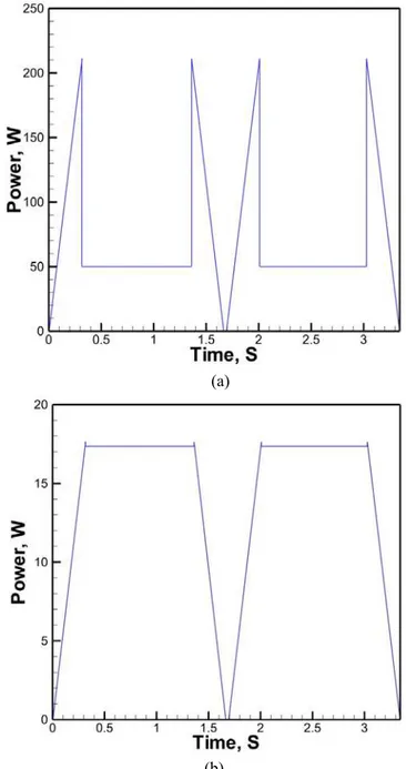
(1) The symbols ρ, c, k and T mean the density, specific heat, thermal conductivity, and temperature of the ball screw shaft and nut, respectively. Here the temperature T is a function of the spatial coordinates (x, y, z) and time. The ρ, c, k values for computations are 7750kg/m3, 480J/kg-oC and 15.1W/m-oC. Figure 3 exhibits the heat generation by the nut and bearing for a period of 3.43s. The friction effect between the balls and raceways of the nut and bearings is the most important cause for temperature increase.
(a)
(b)
Fig. 3. Heat generation by (a) nut and (b) bearing for a period of 3.43s TABLEI
MAIN COMPONENT PARAMETERS OF THE BALL SCREW FEED DRIVE SYSTEM
Ball screw shaft Ball screw nut
Total Length(mm) 1715 Type FDC
Thread Length(mm) 1295 Length(mm) 143.4
LEAD(mm) 20 Diameter(mm) 70
BCD(mm) 41.4
Outer diameter(mm) Inner diameter(mm)
40
12.7 Bearing
Line number 2 Type TAC
Contact type 4 points OD(mm) 30
Given that the load of the nut contains two parts: the preload and dynamic load,Gnut, the heat generation by the nut (in W), can be described as [11,12]:
. 12
.
0 f0 0nM
Gnut
(2)Here f0 is a factor determined by the nut type and lubrication method; v0is the kinematic viscosity of the lubricant (in m2/s); n is the screw rotating speed (in rpm); M is the total frictional torque of the nut (in N-mm). In this research, Gbearing is the heat generated by a bearing (in W), defined as below [13].
. 10 047 .
1 4nM
Gbearing (3)
The variables n is the rotating speed of a bearing and M is the total frictional torque of bearings, including the frictional torque due to the applied load and the frictional torque due to lubricant viscosity.
The convective heat transfer coefficient h (in W/m2-oC) is computed [14] by
. /d Nuk
h fluid (4)
Here Nusselt number Nu= 0.133Re2/3Pr1/3, while the variables Re and Pr represent Reynolds number and the Prandtl number. The sign kfluid is the thermal conductivity of the surrounding air and d is the outer or inner diameter of the screw shaft (mm). More detailed information can be found in Ref. 15.
In this study, the ball screw is modeled using a linear elasticity approach and assumed as the elastic, homogeneous, and isotropic material. The governing equations for the ball screw deformation are as follows:
. 2 2 x zx yx x x g z y x t
v
(5) . 2 2 y zy xy y y g z x y t v
(6) . 2 2 z yz xz z z g y x z tv
(7) The variablesv
,
and
symbolize the displacement, stress and strain vectors (tensors).
th
D
(8)The symbol εth
is the thermal strain. Given the assumption of a linear elastic response, the stress-strain relationship is given by
D
, where D has the form G G G G G G D 0 0 0 0 0 0 0 0 0 0 0 0 0 0 0 0 0 0 2 0 0 0 2 0 0 0 2 (9)
2 11
E
,
1 2
E
G
(10)
Tth
T
,
,
,
0
,
0
,
0
,
(11)D is the elasticity matrix consisting of the material properties, whereas the properties of E, ν and αare the Young’s modulus, the Poisson’s ratio and the coefficient of thermal expansion (CTE). In this investigation, the values of Young’s modulus, Poisson’s ratio and CTE of the ball screw are set to be 1.93× 10¹¹Pa, 0.31 and 1.16×10⁻⁵m/m-oC. The term ∆T= T-Tref, Tref, is the initial temperature of 27oC. A finite element method was used to solve the ball screw model in accordance with the principal of virtual work. For each element, displacements were defined at the nodes and the associated displacements within the elements were subsequently obtained by means of interpolation of the nodal values by the shape functions. The strain-displacement and stress-strain equations for structure were solved with the Gaussian elimination method for sparse matrices [10].
IV. EXPERIMENTAL MEASUREMENTS
Experimental measurements were conducted to determine the time-dependent distributions of temperature, temperature rise and thermal deformation for validation of the thermal model by FEM and evaluate the performance of the cooling system. Figure 4 illustrates a schematic diagram of the experimental set up, containing the ball screw, driving unit, LNC controller, thermal/laser detection system for measuring temperature/deformation and linked data acquisition system. A continual forward and backward movement of ball screw ensued in a 900-mm range, having 20 mm lead, 41.4 mm BCD and 1715 mm total length. The data processing module consisted of four thermal couples as well as a high-precision Renishaw XL-80 laser system with the test data recorded for every 600s.
Fig. 4. Schematic diagram of the experimental set up
V. RESULTS AND DISCUSSION
of balls as a coil-like circular band fully filled the interior surface of raceways between the screw and nut. Figure 5 displays the numerical grids for system simulations. The mesh setup had three unstructured sections, such as the bearings, shaft and coil-like circular band. Finer grids were paced in the areas near the grooves and the solid surfaces. The average cell length was approximately 0.0015m with the least spacing of 0.0006m to resolve the steep variations of thermal properties near heat sources. The predictions of transient temperature distributions on the surface of the ball screw with different grids and time steps suggested that grid independence could be attained using a mesh setup of 1367867 grids with a time step of 5s.
Fig. 5. Numerical grids of ball screw shaft
In simulations, the reciprocating movements of the nut was at a top speed of 40m/min respecting to the screw shaft with a 3.43-s period. The analysis was based on the rotational speed of 3000 rpm and the initial temperature of 27oC. During the continual operations, Fig. 6 illustrates the temperature and thermal deformation distributions along the axial distance of solid and hollow ball screw shafts at t= 3600s. The frictional heat produces the temperature rise with high temperatures occurred in the core areas of the ball screws for both the solid and hollow ball screws. Owing to the enhanced air cooling performance for the hollow shaft with a larger inner surface of the ball screw as compared to the state of the solid shaft, it can be obviously observed that the temperature rise profile for the former case is relatively lower than that of the latter case.
In the structure analysis, the left side of the ball screw was treated as the free end with the right side maintained as the fixed-end condition. The thermal loads from the temperature distribution predictions were then input to solve the thermal deformation. The predicted results indicated relatively larger local thermal deformations near the high temperature regions occurred at the center of the shaft in general. The thermal deformation distributions showed a great reduction in thermal expansion for the hollow shaft at the left end of the screw. However, for the solid shaft, the thermal deformation can be up to 140 μm near the core region for lack of enhanced air cooling from the inner surface of the screw shaft.
(a)
(b)
Fig. 6. (a) Temperature and (b) thermal deformation distributions of solid and hollow ball screw shafts at t= 3600s
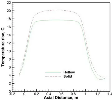
Figure 7 illustrates the temperature distributions along the axial distance of solid and hollow ball screws at 3600s. Since the nut was modeled as a fixed heat source imposed on the ball screw shaft, the high temperature region was located in the core of the shaft (with the axial distance ranging from 0.15 to 0.95m) in response to the thermal loads resulting from the high-speed friction between the nut and ball screw. The steady-state temperature distributions along the axial axis at 2/3 radius from the centerline indicated a reduction in temperature rise up to 16.1% for the hollow shaft because of the enhanced air cooling from the inner surface of the ball screw shaft.
Fig.7. Temperature rise distributions along the axial distance of solid and hollow ball screws at t= 3600s
temperature variations less than 2.1% for reaching toward their steady-state temperature profiles after 3500s.
Monitoring Point
Fig. 8. Time history of predicted temperature rises of monitoring point for solid and hollow ball screws
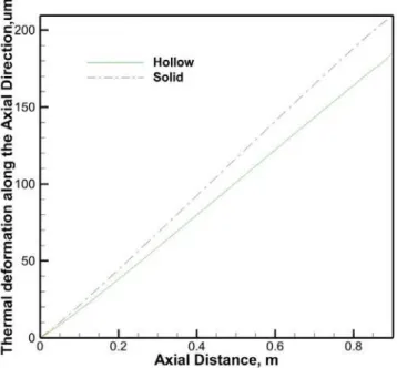
Figure 9 illustrates the thermal deformation distributions along the axial distance of solid and hollow ball screws at t= 3600s. Considering the ball screws fixed in the right bearings of both cases, the temperature rise distributions were utilized to solve the thermal deformations in the axial direction. The computed results indicated that the greatest deformation of the solid ball screw at the axial distance of 0.9m was 209μm, while the deformation of the hollow shaft was 184μm due to a better cooling effect.
Fig. 9. Thermal deformation distributions along the axial distance of solid and hollow ball screws at t= 3600s
The above computational investigations indicate that the ball screws using the solid or hollow design can substantially
affect the thermal deformation results. The simulations show that the hollow shaft design has larger cooling surfaces to achieve a better air-cooling performance, and thereby reduce temperature increase and thermal deformation of a ball screw system. Henceforth, the hollow ball screw was selected as the baseline test platform to validate the current theoretical model for simulation of the associated thermal expansion process. Figure 10 illustrates a comparison of the prediction with the measured temperature rise data along the axial axis of hollow ball screw at t= 3600s. The calculated temperature rise distribution was compared with the measurements of different positions. Overall, the results clearly indicated that the FEM model relatively over-predicted the temperature increase (i.e. 17.7 oC in the central area of the shaft)with the discrepancy within approximately 18.7% in the axial distance of 0.15 to 0.4m, showing that the simulation software may reasonably simulate the thermal expansion phenomenon.
Fig. 10. Comparison of prediction with measured temperature rise data along the axial distance of hollow ball screw at t= 3600s
As far as the transient developments of temperature rises are concerned, Fig. 11 illustrates a comparison of time history of the predictions with measured temperature rises at three locations for the hollow ball screw. At the pre-specified axial distances of 0.05, 0.68 and 1.62m, all three temperature rise profiles grew quickly in the early stage and tended to level off toward their steady-state values of 2.73, 17.2 and 2.66 oC for the test points of 1, 2 and 3, respectively, at t= 3600s. Due to massive heat generated in continuing operations, both the predicted measured results of the test point 2 show a higher temperature rise with the difference under 1.93%, revealing the accuracy of the FEM simulations.
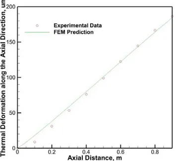
deformation was noted with a large error appeared at the axial distance of 0.1m owing to the over-estimation of temperature rise in this associated area.
#3 #2 #1
Fig. 11. Comparison of the time history of the predictions with measured temperature rises at three locations for hollow ball screw
Fig. 12. Comparison of the prediction with measured thermal deformation data along the axial distance of hollow ball screw at t= 3600s
VI. CONCLUSIONS
The position error of a feed drive system was primarily caused by the thermal deformation of a ball screw shaft. A high-speed ball screw system can generate massive heat after long-term operations, with greater thermal expansion formed, and thereby unfavorably impact the positioning accuracy of the feed drive mechanism. In this study, the computational approach was applied using the FEM to simulate the thermal expansion development for solving the deformation of solid and hollow ball screws. In simulations, we implemented the multi-zone heat loads to treat the heat generation sources
from the frictions between the nut, bearings and the ball screw shaft to emulate reciprocating movements of the nut at a top speed of 40m/min relative to the shaft in a time period of 3.43s. We also employed a three-dimensional unsteady heat conduction equation to determine the steady and transient temperature distributions, as well as temperature rises for calculating the thermal deformations of solid and hollow ball screws. The simulated results reveal that the ball screw shafts using the solid or hollow design can substantially influence the thermal deformation results. The hollow shaft design has relatively larger cooling surfaces to achieve a better cooling outcome for bringing temperature equilibrium of the ball screw quicker, and thereby decreases thermal deformations for improving the positioning accuracy of a ball screw system. Adopting the hollow ball screw shaft as the baseline test platform, both the FEM predictions and measurements demonstrate the temperature rise of 17.7 oC appeared in the central region of the shaft for reaching its steady state at around 3600s. The corresponding thermal deformation along the axial direction can be up to 184μm in operating situations.
ACKNOWLEDGMENT
This study represents part of the results under the financial support of Ministry of Economic Affairs (MOEA) and HIWIN Technologies Corp., Taiwan, ROC (Contract No. 100-EC-17-A-05-S1-189).
REFERENCES
[1] R. Ramesh, M. A. Mannan, A. N. Po, “Error compensation in machine tools—a review. Part II : thermal error,” Int. J. Mach. Tools Manuf., vol. 40, 2000, pp. 1257–1284.
[2] W. S. Yun, S. K. Kim, D. W. Cho, “Thermal error analysis for a CNC lathe feed drive system,” Int. J. Mach. Tools Manuf., vol. 39, 1999,pp. 1087–1101.
[3] J. Bryan, “International status of thermal error research,” Ann. CIRP39, vol. 2, 1990, pp. 645–656.
[4] R. Ramesh, M. A. Mannan, A. N. Po, “Thermal error measurement and modeling in machine tools. Part I. Influence of varying operation conditions,” Int. J. Mach. Tools Manuf., vol. 43, 2003, pp.391–404. [5] J. S. Chen, “A study of thermally induced machine tool errors in real
cutting conditions,” Int. J. Mach. Tools Manuf., vol. 36, 1996, pp. 1401–1411.
[6] S. Li, Y. Zhang, G. Zhang, “A study of pre-compensation for thermal errors of NC machine tools,” Int. J. Mach. Tools Manuf., vol. 37, 1997, pp. 1715–1719.
[7] C. H. Lo, J. Yuan, J. Ni, “An application of real-time error compensation on a turning center,” Int. J. Mach. Tools Manuf., vol. 35, 1995, pp. 1669–1682.
[8] M. Xu, S. Y. Jiang, Y. Cai, “An improved thermal model for machine tool bearings,” Int. J. Mach. Tools Manuf., vol. 47, 2007, pp.53-62.
[9] S. Koda, T. Murata, K. Ueda, T. Sugita, “Automatic compensation of thermal expansion of ball screw in machining centers,” Trans. Jpn. Soc. Mech. Eng. Part C, vol.21, 1990, pp. 154–159.
[10] ANSYS, 13 User Guide, ANSYS Inc., Canonsburg, PA, USA, (Web site: www.ansys.com) 2010
[11] Solution for Heating of Ball Screw and Environmental Engineering, World Manufacturing Engineering and Market, vol. 3, 2004, pp.65-67. [12] A. Verl, S. Frey, Correlation between feed velocity and preloading in
ball screw drives, Ann. CIRP59 2, 2010, pp.429–432.
[13] T. A. Harris, Rolling Bearing Analysis, Wiley & Sons, New York, 1991, pp. 540–560.
[14] H. Li, Y. C. Shin, “Integrated dynamic thermo-mechanical modeling of high speed spindles, part I : model development,” transaction of the ASME, J. Manuf. Sci. Eng.,vol. 126, 2004, pp. 148–158.