Abstract
This paper aims to set up the ball systematic slipping model and analyze the slipping characteristics caused by different factors for a ball screw operating at high speeds. To investigate the ball screw slipping mechanism, transformed coordinate system should be established firstly. Then it is used to set up mathematical modeling for the ball slipping caused by the three main reasons and the speed of slipping can be calculated. Later, the influence of the contact angle, helix angle and screw diameter for ball screw slipping will be analyzed according to the ball slipping model and slipping speeds equation and the slipping analysis will be obtained. Finally, curve of slipping analysis and that of mechanical efficiency of the ball screw analysis by Lin are compared, which will indirectly verify the correctness of the slipping model. The slipping model and the curve of slipping analysis established in this paper will provide theory basis for reducing slipping and improving the mechanical efficiency of a ball screw operating at high speeds.
Keywords
Ball screw; slipping; contact angle; helix angle; slipping analysis.
Modeling and Analyzing the Slipping of the Ball Screw
Nomenclature
1 projection of the i-axis on the t b plane
5 the axis passes through origin o and forms an angle a fromzaxis
,
A B contact point between the ball and the nut, the contact point between the ball and the screw.
1, 2
A A horizontal and vertical distance between A and B'
1, 1 A A
a b half length of the major and minor axis of the elliptical contact area A caused by the ball spin
1, 1 B B
a b half length of the major and minor axis of the elliptical contact area B caused by the ball spin
2, 2 A A
a b half length of the major and minor axis of the elliptical contact area Acaused by orbit motion of the ball
2, 2 B B
a b half length of the major and minor axis of the elliptical contact area Bcaused by orbit motion of the ball
'
B the contact point between the ball and the screw affected by the axial and centrifugal
,
C D the ball spin axis in the ball is formed the two points on the ball surface m
d twice length of rm
,
E F the direction of the slipping angular velocity in the contact points Nannan Xua WenCheng Tangb
School of mechanical Engineering, Southeast University, Nanjing 211189, China.
Corresponding author:
http://dx.doi.org/10.1590/1679-78251292
Latin A m erican Journal of Solids and Structures 12 (2015) 612-623
a
F force applied to the nut in the axial direction
, ,
i j k the spin coordinate system
m,n the contact points between the balls
o origin of the global coordinate system
'
o center of ball
''
o center of ball affected axial force and centrifugal force b
r ball radius m
r projection length of oo'
, ,
t n b the Frenet-Serret coordinate system
1, 1 SA SB
V V the differential slipping velocity at the contact point A and B
2 , 2 Sm Sn
V V the absolute value of slipping speed in the point contact m and n
3, 3
SA SB
V V the absolute value of slipping speed caused by the ball spin in the point contact A and B
4, 4
SA SB
V V the absolute value of slipping speed caused by orbit motion of the ball in the point contact A andB , ,
x y z the global coordinate system screw helix angle
the gyroscopic angle between the i-axis and the 1-axis
' the gyroscopic angle between the 1-axis and the b-axis
,
A B the contact angle between the ball and the nut and between the ball and the screw 1, 2 the elastic deformations in the influence of axial force and centrifugal force N
f ,fS radius of curvature of the nut and screw respectively angular velocity of the rotating screw
m angular velocity of ball revolution along the screw surface R spinning angular velocity of a ball
, ,
t n b components of spinning angular velocity in t-, n- and b-directions, respectively 1, 2, 3 angular velocity of three balls
4, 5 slipping angular velocity produced by the ball rotation on the contact point A and B, respectively 6, 7 slipping angular velocity produced by the ball orbit on the contact point A and B, respectively
1 INTRODUCTION
Due to the relatively low cost and insensitivity to inertia variation and external forces, more and more ball screws are used in the positioning machine tool Wei and Lai (2011). With the increasing application of high-speed and high-precision ball screw, the influence of the ball slipping for the precision and the mechanical efficiency have been widely concerned. Therefore, in recent years, the dynamics of ball screw issues are studied in the process of by many researchers, the influence of slipping for dynamics under the condition of high rotational speeds are slowly realized cannot be ignored Mu and Feng (2011).
Latin A m erican Journal of Solids and Structures 12 (2015) 612-623
and Lin (2003). Jones (1960) introduced the raceway control theory in the process of studying dynamics for the ball bearing. Harris (1984) proposed that raceway control theory is generally valid for high-speed ball bearing and analyzed the slipping behavior of the ball in ball bearing between the balls and the inner raceway, who believed that the slipping is generated by the pressure on the surface of the ball and deemed this slipping behavior would lead to the destruction of the ball bearing. On the basis of the research of Harris, Lin et al. (1994) set up a systematic theoretical method to investigate the kinematics of the ball screw using Frenet–Serret Coordinates. In his study, on the basis of describing the motion of a ball in a ball screw system, he analyzed the slipping between the ball and screw (or the nut) and established the analytical equation, which proved the assumption of no slipping between ball and raceway in the previous is unattainable (Levit, 1963; Drozdov, 1984). Wei et al. (2009) inherited the previous researchers and described the slipping behavior arising at two contact areas between the ball and screw (or nut), while considering variable contact angles and elastic deformations under the running condition. Also, in a later work they (Lin et al., 1994) introduced an analysis method to evaluate the mechanical efficiency of the ball screw and obtained its curve in a closed system. Due to the increasing application of high-speed and high-precision ball screw, Wei et al. (2009); Mu and Feng (2011) set out to establish the analysis model of transmission efficiency for a preload ball screw operating at high speeds, and Mu and Feng (2011) proposed the slipping of ball screw would be effected by the centrifugal force under the high speed state. However, the centrifugal force how to influence on the ball screw slipping hasn’t been further analyzed. Then, Chen and Tang (2014). investigate the dynamic contact stiffness characteristics of a double-nut ball screw operating at high speeds. Then, Wei et al (2009). further analyzed the slipping between the ball and screw (or the nut) considering the effect of pre-load and lubrication.
After the above description, we find that most of the studies on slipping only considered that between the ball and screw (or the nut) in the ball screw. This analysis of slipping can well meet the requirement of the engineering practice for the low and medium speed of ball screw, but the slipping caused by the centrifugal force and between the balls cannot be ignored at high-speed. Harris analyzed the slipping of balls in ball bearing operating at the high-speed. The advantages are that he considering the influence of centrifugal force and spin, but he gave no details of the derivation and theoretical proof and did not consider the slip between the balls.
Latin A m erican Journal of Solids and Structures 12 (2015) 612-623
2 THEORETICAL ANALYSIS
In order to better analyze the modeling and slipping for the ball screw, the establishment of the three coordinate system to describe three degrees of freedom and the contact behavior is necessary. The global coordinate system, ( , , )x y z the Frenet-Serret coordinate system, ( , , )t n b used by Wei and
Lin is decided to be adopted. Meanwhile some changes of kinematics model by Wei are necessary to facilitate the analysis of a ball slipping model, which can be shown in Figure 1.
Figure 1: The slipping analysis model of a ball. Figure 2: Location of contact points on the b n plane.
2.1 Differential slipping
According to the working principle of ball screw and the characteristics of the Frenet-Serret Coordinates, it can be obtained that the ball can only move in thet direction and the ball is
confined along the screw’s (or nut’s) raceway on the b n plane. Physically, the two contact points
between the ball and raceway must be located on the b n plane too, as shown in Figure 2. The
point A represents the contact point between the ball and the nut, as well as the point B represent
the contact point between the ball and the screw. A and B represent the contact angle between the ball and the nut and between the ball and the screw, respectively. rb is the radius of the ball.
According to the study of Wei et al (2009), the absolute value of the differential slipping velocity at the contact point A and B is given as:
2 2
1 ( ) ( cos sin )
SA b t m b b A n A
V r d r (1)
2
2 2
1 ( sin ) ( ) [( cos )cos sin ]
SB b t m b b B n B
V r d r 2)
where, cos
m
d r
,
: angular velocity of the screw
m: the ball’s angular velocity of revolution, which can be obtained by the study of Wei et al. (2009)
t , n , b : angular velocity components in the t , n , and b directs by R and t cos sin '
R , b Rcos cos ', n Rsin .
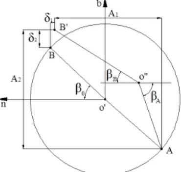
Aand B calculation is as follows and shown in Figure 3.
Latin A m erican Journal of Solids and Structures 12 (2015) 612-623
Figure 3: A model for calculating the contact angle. Figure 4: Slipping conditions between the balls.
According to the orbit control theory, ball screw in the motion state was affected by the axial force and centrifugal force, the contact point B and center of ball O' occur deviation (After deviation B', and O'' respectively), which led to the A and B have changed. AB' the length of the and axis are divided into A1 and A2. Geometric analyses can be given:
1
'' cos A ' '' cos B
AO B O A (3.a)
2
'' sin A ' '' sin B
AO B O A (3.b)
1
'' 2 (N 0.5)b
AO f r (3.c)
2
' '' 2 (S 0.5)b
B O f r (3.d)
1 cos 0 1
A AB (3.e)
2 sin o 2
A AB (3.f)
where
N
f ,fS: radius of curvature of the nut and screw respectively,
1, 2: the elastic deformations in the influence of axial force and centrifugal force
The solutions for above equation can be obtained the contact angles A and B.
2.2 Slipping between the Balls
Figure 4 shows three balls will be rotation clockwise at a rate of 1 , 2 and 3 respectively under the action of friction when the screw rotates anticlockwise with angular velocity for . If the direction of screw rotation does not change, no matter how to change the speed of 1, 2 and 3, the contact point m , n will produce the relative slipping angular speed of ( 1 2) and
2 3
( ), respectively. Analysis of ball movement characteristics can be obtained that 1 2
2 3 2( R m). Therefore, the absolute value of slipping speed VSm2 and VSn2 in the point
contact and are stated as(3)
2 2
2 2 ( )
Sm Sn b R m
V V r (4)
Latin A m erican Journal of Solids and Structures 12 (2015) 612-623 2.3 Slipping caused by gyroscopic effect
The ball do spin movement and orbit around the axis of screw when ball screw is working, and it will be subject to the effect of gyroscopic moment, which will cause the ball slipping. According to the causes of gyroscopic effect two aspects - spin and orbit motion, it will be a detailed analysis of them in this section, respectively.
2.3.1 Slipping caused by the ball spin
As elastomer of ball movement in the raceway of the elastomer screw and nut, as shown in Figure 3, the contact points A and B will become a small plane under radial and axial loads, respectively.
According to the principle of Hertzian contact, the contact plane can be considered as an ellipse. The ball rotation angular velocity R will produce slipping angular velocity 5 and 4 on the contact point A and B, respectively, as shown in Figure 5. Ball spin axis in the ball is formed the
two points on the ball surface are defined as C and D .The direction of the slipping angular
velocity in the contact points is formed by centered at C and D.
(a) (b)
Figure 5: (a) Spin slipping of ball-nut contact. (b) Spin slipping of ball-screw contact.
According to the geometric relations of Figure 5, 5 and 4 calculation is as follows:
5
sin
cos cos
R n
B B
(5.a)
4
sin
cos cos
R n
A A
(5.b)
Therefore, the absolute value of slipping speed VSA3 and VSB3 in the point contact and are
stated as:
2 2
2 2 2
3 5
2 sin
( ) sin
2 cos
B R
SA b
B
Latin A m erican Journal of Solids and Structures 12 (2015) 612-623
2 2
2 2 2
3 4
2 sin
( ) sin
2 cos
A R
SB b
A
V BD r (6.b)
2.3.2 Slipping caused by orbit motion of the ball
As shown in Figure 6, the intersection of n axis and 5 axis set as E and F. The ball orbit angular
velocity m will produce slipping angular velocity 7 and 6 on the contact point A and B ,
respectively. The direction of the slipping angular velocity in the contact points is formed by centered on E and F.
(a) (b)
Figure 6: (a) Orbit slipping of ball-nut contact. (b) Orbit slipping of ball-screw contact.
According to the geometric relations of Figure 6, 7 and 6 calculation is as follows:
7 Bsin B mcos sin B (7.a)
6 Asin A ( m)cos sin A (7.b)
where, the angular velocity of the nut (or screw) relative to the ball is defined to be B( A) cos
B m , A ( m)cos .
Therefore, the absolute value of slipping speed VSA4 and VSB4 in the point contact A and B are
stated as:
2
2
2 2 2
4 ( ) 7 2 cos cos sin
2 2
m m
SA b b B m B
d d
V EA r r (8.a)
2
2
2 2 2
4 ( ) 6 2 cos cos sin
2 2
m m
SB b b A m A
d d
V FB r r (8.b)
( ) ( )
Latin A m erican Journal of Solids and Structures 12 (2015) 612-623
3 RESULTS AND DISCUSSION
Because the slipping is closely linked to mechanical efficiency of ball screw, the slipping analysis of model in this paper with mechanical efficiency analysis by Lin can be compared and validated. There are many factors which can affect the slipping of ball screw. Now the main performance parameters of ball screw that greatly influence the slipping to the ball screw are chosen. They are the contact angle, helix angle, screw diameter. In this section these factors are analyzed and discussed respectively.
3.1 The influence of the contact angle to ball screw slipping
The change of contact angle in contact surface of ball and raceway directly affects the slipping of ball screw. It is an important geometric parameter which will influence the properties of ball screw pair. So the change of contact angle is carried into the analysis and discussion for ball screw slipping at first. To analyze the impact of the contact angle on the slipping of ball screw, other parameters affecting ball screw slipping are presupposed as constant value, as shown in Table 1.
Parameters Value Units
Ball diameter (Dw) 6 mm
screw diameter (dm) 40 mm
helix angle ( ) 10 degree
screw angular velocity ( ) 5000 rpm
preload (Fa) 2000 N
Table 1.
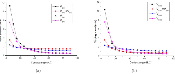
The range of A for 0-90 and the fixed value B for 45 are taken. The parameters in Table 1 are plugged in Eq.(1), Eq.(4), Eq.(6a) and Eq.(8a), respectively, which lead to A of ball screw slipping analysis results, as shown in Figure 7(a).
(a) (b)
Latin A m erican Journal of Solids and Structures 12 (2015) 612-623
In a similar way, the range of B for 0-90 and the fixed value A for 45 are taken. The parameters in Table 1 are plugged in Eq.(2), Eq.(4), Eq.(6b) and Eq.(8b) respectively, which can result into B of ball screw slipping analysis as shown in Figure 7(b).
Figure 7 shows that all kinds of slipping speed of the ball are going down gradually with the increase of contact angle. This is consistent with the conclusion got from the efficiency curve by Lin, which indirect verifies the correctness of the slipping model. From Figure 7 can be found that the change of the contact angle has great influence on differential slipping and slipping caused by orbit motion of the ball, but has less effect on the slipping between the balls and that caused by the ball spin. For the relationship between differential slipping and slipping caused by orbit motion of the ball and the change of contact angle has higher sensitivity, discovered by Eq.(1) and Eq.(8a). According to the structure of the ball screw, it can be obtained that the centrifugal force of contact point Ais greater than the contact point B ,which is consistent with the slipping caused by orbit
motion of contact point A is greater than the contact point B displayed in Figure 7. Therefore, in
order to reduce the ball slipping, ball screw pair should properly increase the contact angle in the design process, while at the same time we should pay attention to the growth of slipping of the contact angle after more than evident 40 degrees is obviously decreasing.
3.2 The influence of the helix angle to ball screw slipping
To analyze the influence of the helix angle to the slipping of ball screw, other parameters affect ball screw slipping are presupposed as constant value which similar to analysis method in the previous section, as shown in Table 2. As centrifugal force will increase contact angle of ball-nut side and decrease contact angle of ball-screw side at the same time at screw rotational speed 5000 rpm. In order to accord with real industry application, A = 50, B= 40 are assumed.
Parameters Value Units
Ball diameter (Dw) 6 mm
screw diameter (dm) 40 mm
contact angle ( A) 50 degree
contact angle ( B) 40 degree
screw angular velocity ( ) 5000 rpm
preload (Fa) 2000 N
Table 2.
In the contact point A of the ball and the nut and the contact pointB of the ball and the screw
is different, so should be separately analyzed and discussed. The range of for 0-90 is set. The parameters in Table 2 are plugged in Eq.(1), Eq.(4), Eq.(6a) and Eq.(8a) respectively, which can get slipping analysis results of the contact pointA.In a similar way, the parameters in Table 2 are
plugged in Eq.(2), Eq.(4), Eq.(6b) and Eq.(8b) respectively, which can get slipping analysis results of the contact point B, as shown in Figure 8.
Latin A m erican Journal of Solids and Structures 12 (2015) 612-623
degrees, differential slipping and slipping caused by orbit motion of the ball rise rapidly, this is due to that the helix angle has greatly limited the ball rolling. This is also consistent with the curve of the efficiency of the conclusion by Lin, which further demonstrates the correctness of the slipping model. From the Figure 8, we can find if we want to raise the efficiency and reduce the ball slipping, the helix angle in the design process should be increased but the same time below the 75 degrees. In addition, more attentions should be paid to that the growth of slipping is obviously decreased after the contact angle is more than 10 degrees.
(a) (b)
Figure 8: (a) Helix angle for contact point Aslipping analysis. (b) Helix angle for contact point Bslipping analysis.
3.3 The influence of the screw diameter to ball screw slipping
To analyze the influence of the screw diameter to the slipping of ball screw, similar to analysis method in the previous section, other parameters affecting ball screw slipping are presupposed as constant value, as shown in Table 3.
Parameters Value Units
Ball diameter (Dw) 6 mm
helix angle ( ) 10 degree
contact angle ( A) 50 degree
contact angle ( B) 40 degree
screw angular velocity ( ) 5000 rpm
preload (Fa) 2000 N
Table 3.
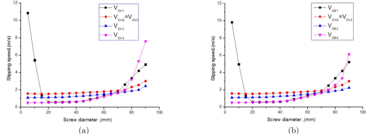
The range of dm for 0-90 is set. The parameters in Table 3 are plugged in Eq.(1), Eq.(4), Eq.(6a)
and Eq.(8a) respectively, which can get slipping analysis results of the contact point A.In a similar
way, the parameters in Table 3 are plugged in Eq.(2), Eq.(4), Eq.(6b) and Eq.(8b) respectively, which can get slipping analysis results of the contact point B, as shown in Figure 9.
Latin A m erican Journal of Solids and Structures 12 (2015) 612-623
diameter, the ball received by centrifugal force and orbital trajectory is expanding, which lead to the increase of slipping. If the diameter of the screw is smaller than the ball, the ball in the ball screw cannot work properly, so differential slipping will produce large slipping during the initial position in the x-axis of Figure 9. But with the increase of screw diameter (to the location of the 20
or so), differential slipping is get normal. Then, as the screw diameter continues to increase, slipping began to rise. By this time the increase of differential slipping with other slipping has the same reason (the ball received by centrifugal force and orbital trajectory is expanding). Therefore, in order to raise the efficiency and reduce the ball slipping, ball screw pair should try to reduce the diameter of the screw in the design process on the premise of meet the working strength.
(a) (b)
Figure 9: (a) Screw diameter for contact point slipping analysis. (b) Screw diameter for contact point slipping analysis.
4 CONCLUSIONS
1 All kinds of slipping speed of the ball is getting down gradually with the increase of contact angle, but at the same time we should pay attention that the growth of slipping of the contact angle after more than 40 degrees is obviously decreased. This is not only consistent with the curve of the efficiency of the conclusion by Lin, which indirect verify the correctness of the analysis of the slipping mode, but also provides an idea how to choose the proper contact angle to reduce the slipping.
2 All kinds of slipping speed of the ball is getting down gradually with the increase of helix angle until the helix angle to reach 75 degrees, at the same time we should pay attention that the growth of slipping of the contact angle after more than 10 degrees is obviously decreased. However, with the increase of helix angle to 75 degrees, differential slipping and slipping caused by orbit motion of the ball rise rapidly. This is also consistent with the curve of the efficiency of the conclusion by Lin, which further verifies the analysis of the slipping model.
Latin A m erican Journal of Solids and Structures 12 (2015) 612-623
reduce slipping and improve the work efficiency of the screw should be reduce the differential slipping and slipping caused by orbit motion of the ball.
Acknowledgements
The authors would like to thank for the continuous funding support of the National Science and Technology Major Project of the Ministry of Science and Technology of China (2013ZX04008011).
References
Chen, Y., Tang, W., (2014). Dynamic contact stiffness analysis of a double-nut ball screw based on a quasi-static method. J. Mech. Mach. Theory 73: 76–90.
Drozdov, Y.N., (1984). Calculating the wear of a screw and nut transmission with skidding friction. J. Soviet Engineering Research 4(5): 1–12.
Harris, T.A., (1984). Rolling Bearing Analysis 2nd ed, New York: John Wiley.
Jones, A.B., (1960). A general theory for elastically constrained ball and radial roller bearings under arbitrary load and velocity conditions. J. ASME Journal of Basic Engineering 12(2): 309–20.
Levit, G.A., (1963). Recirculating ball screw and nut units. J. Machines and Tooling, XXXIV (4): 3–8.
Lin, M.C., Ravani, B., Velinsky, S.A., (1994). Design of the Ball Screw Mechanism for Optimal Efficiency. J. Mech. Des. 116: 856–861.
Lin, M.C., Ravani, B., Velinsky, S.A., (1994). Kinematics of the ball screw mechanism. J. Mech. Des. 116: 849–855. Mu, S.G., Feng, X.Y., (2011). Study of the dynamic characteristic of high-speed ball screw. J. Hunan Univ. (Nat. Sci.) 38: 26–29.
Wei, C.-C., Lai, R.-S., (2011). Kinematical analyses and transmission efficiency of a preloaded ball screw operating at high rotational speeds. J. Mech. Mach. Theory 46: 880–898.
Wei, C.C., Lin, J.F., (2003). Kinematic analysis of the ball screw mechanism considering variable contact angles and elastic deformations. J. Mech. Des. 125: 717–733.