THE STUDY OF SHIPS BEHAVIOR DURING PORT MANEUVERING WITH TUGS
Alecu TOMA 1 Valentin ONCICA2 Dinu ATODIRESEI3
1
Asistent professor, Eng., PhD, „Mircea cel Batran” Naval Academy, Constanta, Romania,
Asistent professor, Eng., PhD, „Mircea cel Batran” Naval Academy, Constanta, Romania,
Advanced instructor, Eng., PhD, „Mircea cel Batran” Naval Academy, Constanta, Romania,
Abstract: Most of the time, during the turning, the motion of the ship is not a perfect circle because there are several forces acting on the ship and these forces change continuously. In this paper we study the real motion of the ship when a transverse force is applied by a tug at the different points of the moving or stationary ship. The pivot point is useful by seafarers to visualise the rotation of a ship during its combined rotation/translation movement. It is the result of all forces acting on the ship and its position changes continuously during the ship’s displacement, depending on the forces involved.The centre of drift is the point at which the resultant of all hydrodynamic forces acts: underwater resistance, lift and drag as a function of speed and drift angle. The underwater resistance force exists both for pure headway or sternway motion and for all lateral motions. It induces flow velocities below and beside the hull. On a real turning circle the heading is not completely constant as it undergoes small variations due to small changes in the forces acting on the ship: local variations in water depth, variations in distance from the shore line, local currents or wind gusts.
Keywords: ship behavior,tug, manoeuvring, pivot point
Introduction
The shipping industry has always been concerned with safe towing and mooring practices and with making sure that shipboard staff are aware of the hazard associated with these operations. Nowadays port maneuvers are executed almost entirely by tugs that have become more efficient and capable of exerting forces that are well in excess of the necessary mooring forces. Using tugs for escorting, station keeping, and unberthing is becoming a widely used method of risk management at ports and harbours worldwide. Harbour tugs may be used in towing mode as well as a pushing and appropriate push points normally located near a transverse bulkhead. We note that with the escorted vessel unerway, and the tug applying a towing force at the angle to the ship’s heading, the water flow against the hull and the tug’s own displacement will generate hydrodinamic forces. When combined with the propulsion forces these may give a resultant force which influence ship maneuvering.
Wider acceptance of recomandations in both towing and mooring will furder ensure that operations of tugs with ships can be carried out safely and efficiently.
1. Shiphandling theory
The 1st Newton’s law of motion says that unles acted upon by an external force a ship in motion tends to stay in motion due to her momentum, a ship at rest tands to stay at rest due to her inertia. The 2nd Newton’s law is given by the mathematical relationship: F = m x a, where: F is force (Newton), m is mass (kg), and a is acceleration of mass (m/s2).
In the mathematical relationship mass m includes the ship’s displacement and the “added mass” which reprezents the force needed to change the ship’s velocity. The added mass is related to the ship’s accelerations and ship’s decelerations. It is not negligible as it may amount to around 10% of the ship’s displacement. The added mass is nil when the ship is at rest, and greater when the ship is involved in oscillatory motions.
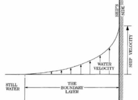
The boundary layer is located (Fig. 1) between the hull and the still water area. Due to friction of the hull on the water body and owing to viscosity, the large flow velocity gradient and the shear stress induce turbulence.
109 DOI: 10.21279/1454-864X-16-I2-017
Fig. 1 Water velocity depending on distance to the hull in the boundary layer
The 3rd Newton’s law distinguishes between actions such as those generated by wind, current, propeller, rudder, tug, and reactions such as underwater resistance.
We difine the ship neutral point as a physical point whose position depends on the centre of gravity, the centre of buoyancy, the centre of the underwater area (shape of the hull, trim), and of the pressure field around the hull (dead in the water, headway or sternway).
If the ship is dead in the water, the neutral point is close to the centre of gravity and to the centre of wet area. If the ship is making headway, the neutral point is shifted forward. If the ship is making sternway, the neutral point is shifted backwards.
The underwater resistance force (UWR) exists for headway motion or sternway motion and for all lateral motions tipes. It induces flow velocities below and beside the hull and justifies the use of Bernoulli's law.
When the rudder is put over to port (Fig. 2), it makes an angle with the water flow and so acts as a foil to generate a sideways force that swings the ship head to port. In doing so, higher pressure builds up against the starboard side of the hull and the entire hull form will be acting as a foil that makes the ship follow a circular track to port. The ship moves under the combined effect of three forces, acceleration of masses (including added mass), viscous dissipation (friction), hydrostatic forces.
Fig. 2 Forces acting on a ship when the rudder is put over to port
The pivot point (PP) is the point with no drift angle (described by the British Admiralty), and is used to visualise the rotation of a ship during its combined rotation movement. It is the result of all forces acting on the ship and its position changes continuously during the ship’s displacement, depending on the numerous and variable forces involved. The pivot point is positioned on the other side of the neutral point, at a distance depending on the length of the lever arm and the intensity of the force. When the tug comes closer to the neutral point, the lever arm is reduced: less rotation, more translation.
The position of the PP can be computed for any track of the ship as a geometrical matter by means of a vector approach using the bow and stern of two successive ship positions. The connecting line between these 2 components (bow 1 to bow 2, stern 1 to stern 2) will cross the ship axis at PP.
The position of PP is shown as a percentage of the ship length, starting from the bow. The position is positive if it is behind the bow, and negative if it is in front of the bow. PP is located around 35% for most of the time but for exemple with tug action, PP can be behind the stern (> 100%) if drift < 0°.
2. The use of tugs in ships maneuvering
Because actual ships that operate in the ports are very high, even if they are very maneuverable, harbor towage is mandatory in almost all the world's ports. Tow boats are used in a variety of ways all over the world. To hold a ship stopped in a broadside current or broadside wind, the tug force must equal the lateral forces of current and wind on the ship. To increase or decrease a vessel's movement, the tugs must also overcome the vessel's inertia. To turn a vessel when stopped, the tugs must overcome lateral resistance and rotational inertia.
2.1 Approaching a berth
To approach a vessel berth side, the tug have to push very close to the ships pivot point in the desired direction of movement in conjunction with full rudder and short kicks ahead by the ship. In this position it is working on a turning lever that is either very small, or negligible and as a consequence it will be relatively poor at assisting the ship to develop rate of turn or swing. By working close to the ship's PP it will be most effective in assisting the ship to develop lateral movement of the ship (Fig. 3).
110 DOI: 10.21279/1454-864X-16-I2-017
Fig. 3 Approaching a berth
With the tug being used in this position, there is a similarity to driving a ship with a bow thruster, but with the advantage of much greater power over a 360° arc of operation.
2.2 Turning a vessel
To turn a ship the tug have to push some distance from the ship's PP, working on a substantial turning lever and placed to help increase or decrease the ship's rate of turn (Fig. 4).
Fig. 4 Turning a vessel
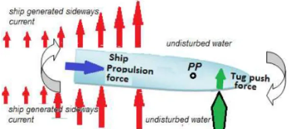
During the lateral movement of the ship, she creates a vacuum which in turn drags a mass of water towards the shipside. The outer shipside also pushes a mass of water away. This phenomenon has been called ship generated sideways current.
3. The effect of the sideway current on the ship moving ahead
The ship, with its rotational inertia, keeps on turning, but the rate of turn will reduce due to water friction. The ship generated sideways current with its own inertia, will catch the stern and continue to push it sideways, while the forward part of the ship is in undisturbed water. This force, acting more or less sideways on the stern contributes in moving the PP more forward.
The ship generated sideways current effect is relatively more important on ships with high draft. The rotation effect will be more noticeable on smallest draft ships (Fig. 5).
Fig. 5 The behavior of a ship moving ahead pushed sideways by a forward tug
If the ship is moving ahead, and the forward escort tug will start pushing in order to direct the bow to port, the ship will have sideways motion and a rotation to portside, since the force is acting forward of the centre of lateral resistance.
Fig. 6 The behavior of a ship pushed sideways by a forward tug
As the ship moves ahead, the bow will come in an undisturbed water. The stern will be affected by the ship generated sideways current that has started to develop, causing a turning moment that will reduce the port swing and can even initiate a starboard swing. When the ship starts a starboard swing, the stern, due to the rotation, keeps on generating more sideways current than the forward part of the ship, thus amplifying the turning moment (Fig. 6).
5. Case study - interaction between a 82000 DWT oil tanker and a tug
5.1 Scenario of the simulation
In this section we will present a qualitative assessment of the interaction between a oil tanker ship type and a tug during the port maneuvers. Tests were conducted in the NTPRO 5000 Ship simulator of „Mircea cel Batran” Naval Academy.
111 DOI: 10.21279/1454-864X-16-I2-017
Fig. 7 Weather information (screen capture)
Hydrometeorological conditions (Fig. 7) during the tests - calm and without current marine.
Fig. 8 Oil tanker – overall picture (screen capture)
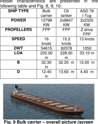
Vessel characteristics are presented in the following table and Fig. 8, 9, 10:
Fig. 9 Bulk carrier – overall picture (screen capture)
Fig. 10 78 t Tug – overall picture (screen capture)
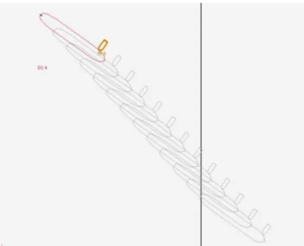
5.2 Test 1: Tug starts to push when the bulk carrier is drifting
Stage 1. Time 00.00
- Bulk carrier: drifting, engine RPM 0 (Rotations Per Minute), COG 900 (Course Over Ground), SOG 0 knots 0 (Speed Over Ground).
- Tug standby in portside, prepared to push the bow with full power.
Fig. 11 Tug prepared to push the bow with full power (screen capture)
Stage 2. Time 00.01
- Bulk carrier drifting, RPM 0, COG 900 increasing trend, SOG 0 knots.
- Tug pushing the bow with full power in portside of the Bulk carrier.
Fig. 12 Tug pushing the bow with full power in portside of the Bulk carrier (screen capture)
Stage 3. Time 00.03
- Bulk carrier driftind, RPM 0, COG 930 increasing trend, SOG 0 knots.
SHIP TYPE Bulk carrier
Oil tanker
ASD 78 t Tug POWER 12799
KW
2x9847 KW
2x2320 KW PROPELLERS FPP FPP Z drive
FPP
SPEED 16
knots
15.2 knots
13 knots
DWT 54615 82078 1050
LOA 220.00
m
228.00 m
33.10 m
B 32.30
m
32.20 m 12.00 m
D 12.40
m
13.60 m 4.40 m
112 DOI: 10.21279/1454-864X-16-I2-017
- Tug pushing the bow with full power in portside of the Bulk carrier.
Fig. 13 Tug pushing the bow with full power in portside of the Bulk carrier
Stage 4. Time 00.10
- Bulk carrier on the way, RPM 105, COG 125 fast increasing trend, SOG 0 knots,
increasing.
- Tug pushing the bow with full power in portside of the Bulk carrier.
Fig. 14 Tug pushing the bow with full power in portside of the Bulk carrier
Stage 5. Time 00.12
- Bulk carrier on the way, RPM 105, COG 1300 decreasing trend, SOG 3 knots, increasing.
- Tug pushing the bow with full power in portside of the Bulk carrier.
Fig. 15 Tug pushing the bow with full power in portside of the Bulk carrier
Stage 6. Time 00.15
- Bulk carrier on the way, RPM 105, COG 1150 decreasing trend, SOG 6 knots, increasing.
- Tug pushing the bow with full power in portside of the Bulk carrier.
Fig. 16 Tug pushing the bow with full power in portside of the Bulk carrier
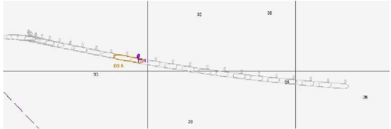
6.3 Test 2:Tug starts to push when the oil tanker ship is on the way
Stage 1. Time 00.00
- Oil tanker: on the way, engine RPM 96, COG 900, SOG 0 knots increasing.
- Tug standby in portside, prepared to push the bow with full power.
Fig. 17 Tug standby in portside, prepared to push
113 DOI: 10.21279/1454-864X-16-I2-017
Stage 2. Time 00.03
- oil tanker on the way, RPM 96, COG 900, SOG 3 knots fast increasing.
- Tug on the way to push the bow with full power in portside of the ship.
Fig. 18 Tug pushing the bow with full power in portside of the oil tanker.
Stage 3. Time 00.05
- oil tanker on the way, RPM 96, COG 930 slow increasing trend, SOG 6 knots increasing.
- Tug pushing the bow with full power in portside of the ship.
Fig. 19 Tug pushing the bow with full power in portside of the oil tanker
Stage 4. Time 00.07
- oil tanker on the way, RPM 96, COG 950 increasing trend, SOG 7 knots, increasing.
- Tug pushing the bow with full power in portside of the ship.
Fig. 20 Tug pushing the bow with full power in portside of the oil tanker
Stage 5. Time 00.12
- oil tanker on the way, RPM 96, COG 980, SOG 9 knots, increasing
- Tug pushing the bow with full power in portside of the ship
Fig. 21 Tug pushing the bow with full power in portside of the oil tanker
Stage 6. Time 00.15
- oil tanker on the way, RPM 96, COG 970 very slow decreasing trend, SOG 12 knots, increasing
- Tug pushing the bow with full power in portside of the ship
Fig. 22 Tug pushing the bow with full power in portside of the oil tanker
Stage 7. Time 00.15
- oil tanker on the way, RPM 96, COG 970 very slow decreasing, SOG 12 knots, increasing
- Tug pushing the bow with full power in portside of the ship
114 DOI: 10.21279/1454-864X-16-I2-017
Fig. 22 Tug pushing the bow with full power in portside of the oil tanker
CONCLUSIONS
In the first test, COG increase over time, with the tug pushing up to a maximum value of the 1300. After 12 min, COG value stabilizes, with slow increasing vessel speed, then begins to decrease continuously and the ship returns to port enrolling on a curve yaw (Fig. 11-16).
In the second test, COG increase over time but up to a maximum value 980 value at which stabilizes but the COG trend is to slow decrease (Fig. 17-22).
The explanation for the difference observed in the two tests is the right pitch propeller which, unlike chemical tanker ship that has two propellers, will increase the yaw moment of the vessel to port because of the propeller turning moment.
BIBLIOGRAPHY
[1] Clark, I. C., Ship dynamics for mariners, Nautical Institute, 2005
[2] Hugues Cauvier, THE PIVOT POINT, Editorial in The pilot, october 2008, nr. 295
[3] Van Hilten, Max [2001], “Unpredictable behaviour; example of a reason to reconsider the theory of manoeuvring for navigators”, Proc. of IMSF Annual General Meeting Genova.
[4] *** Recommendations for ships’ fittings for use with tugs with particular reference to escorting and other high load operations, ISBN 1856092216, bublished by Witherby & CO LTD London, England
[5]Andrei Pocora, Sergiu Lupu, Cosmin Katona – Simulated propeller walk on a 13.300 TEU container ship, “Mircea cel Batran” Naval Academy Scientific Bulletin, Volume XVIII – 2015 – Issue 2, pag 55-59 ISSN 1454-864X, Constanța 2015
115 DOI: 10.21279/1454-864X-16-I2-017