ISSN 1546-9239
© 2007 Science Publications
Corresponding Author: Ali Bonakdar, Tactile Sensing and Surgical Robotics Lab, Department of Mechanical and Industrial Engineering, Concordia University, EV 04-139, 1515, St. Catherine west, Montreal, Quebec, Canada H3G 2W1
Investigations on the Grasping Contact Analysis of Biological Tissues
With Applications in Minimally Invasive Surgery
Ali Bonakdar, Javad Dargahi and Rama Bhat
Tactile Sensing and Surgical Robotics Lab, Department of Mechanical and Industrial Engineering Concordia University, EV 04-139, 1515, St. Catherine west, Montreal, Quebec
Canada H3G 2W1
Abstract: Analytical and finite element methods are employed to determine the contact pressure on
the surface of a tissue being grasped by an endoscopic grasper, in Minimally Invasive Surgery (MIS). Normally, an endoscopic grasper is corrugated (teeth-like) in order to grasp slippery tissues. It is highly important to avoid damage to the tissues while grasping and manipulation during endoscopic surgery. Therefore, it is essential to determine the exact contact pressure on the surface of the tissue. To this end, initially a comprehensive closed form, finite element and experimental analysis of grasping contact pressure on viscoelastic materials which have similar properties as that of biological tissues is studied. The behavior of a grasper with wedge-like teeth, when pressed into a linear viscoelastic material is examined. Initially, a single wedge penetrating into a solid is studied and then is extended to the grasper. The elastic wedge indentation is the basis of the closed form analysis and the effects of time are included in the equations by considering the corresponding integral operator from viscoelastic stress-stain relations. In addition, a finite element analysis is carried out in Ansys-10 software. Finally, the experimental results are presented to validate both analytical and FEM results. The results of this study provide a closed form expression for grasping contact pressure force and contact area along with the variations of stress in tissue obtained through FEM analysis. The variation of contact pressure and the rate of growth of the contact area with time are presented.
Keywords: Grasping Analysis, Finite Element, Viscoelastic, Tissue, Minimally Invasive Surgery
INTRODUCTION
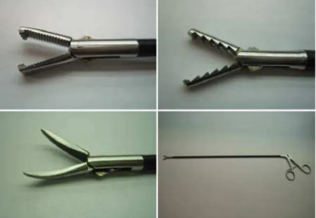
Minimally invasive surgery (MIS), also called endoscopic surgery, is regarded as a powerful technique that facilitates a faster patient recovery [1]. MIS is a procedure carried out by a surgeon through a small incision using specialized surgical equipment like endoscopic tools or other visualization devices, not requiring direct access. The endoscopic tools have a teeth-like grasper for easy grasping of various slippery tissues. Figure 1 shows some typical endoscopic graspers. This surgical device is of great use during manipulation tasks such as grasping the internal organs, gentle load transfer during lifting, suturing and removing tissues [2]. This surgical approach offers several advantages over traditional open surgery such as reduced trauma, less pain, and shorter recovery times for the patient. For many operations, post-operative pain is significantly reduced and leads to faster discharge from the hospital, and a more rapid return to normal activities [3,4].
Despite some advantages of MIS compared to the traditional surgery, almost complete lack of sense of
touch that may cause damage to the tissue is a major drawback of this technology. In order to prevent any damages on the organ and tissues, determining the contact pressure and force between grasper and organ is very important. Comprehensive theoretical analysis as well as measurements using electromechanical sensors can be employed to determine the contact pressure and force on tissues.
the contact pressure and force between tissue and grasper explicitly. Moreover the state of stress in the tissues is also an important problem which has not been studied well so far.
Fig. 1: Typical endoscopic tools and graspers
Grasping contact analysis is mainly affected by material behavior, shape of the indenter and friction between the grasper and object. Since the tissues are viscoelastic, our analysis is based on the theory of contacts on viscoelastic models. The theoretical studies of linear viscoelastic bodies in contact, became active since 1950s by the work of Read [14], Lee [15], Radok [16], Lee and Radok [17], Hunter [18], Graham [19,20] and Ting [21,22]. In recent years, a number of authors have extended the early work to the analysis of indentation measurements in viscoelastic solids using either conical or spherical indenters [23-26]. Bonakdar et al [27,28] recently studied the grasping contact pressure for both elastic and viscoelastic materials with different shapes of graspers analytically. In the present paper, we investigate teeth-like contact grasping in linear viscoelastic materials using analytical and finite element methods. Finally, the experimental tests will be carried out to validate our analysis.
MATERIALS AND METHODS
1. Viscoelastic Contact Analysis
We will use an idealized viscoelastic material, which demonstrate the effect of delayed elasticity (Kelvin Model). This model includes a spring of modulus g1 parallel to a dashpot of viscosityη, which are in series with another spring with modulus g2. For this material, the creep response to a step change in stress s0 is expressed as [29],
0 1 2
1 0
1 [1 exp( )]}
1 1 { ) ( 5 . 0 )
( tT s
g g s t J t
e = = + − − (1)
where e(t) is time dependent strain, J1(t) is the creep compliance and T1=η g2. The response to a step change of strain e0 is written as,
0 2 1 2 2 1 1
0 [ exp( )]}
) ( 2 )
( g g tT e
g g g e t G t
s + −
+ =
= (2)
where s(t) is time dependent stress, G(t) is the shear relaxation function or time dependent shear modulus and T2 =η (g1+g2).
In the present paper, a rigid and frictionless wedge which is indenting normally into the viscoelastic solid, as shown in figure 2, is considered. The problem is solved based on the linear theory of viscoelasticity and the solid is assumed to be isotropic and homogeneous.
The contact pressure between a wedge and an elastic solid is expressed as [30],
) ( cosh ) 1 ( cot ) ( 1 2 x a E x p − − = ν π
α (3)
where E, ν and a are Young’s modulus, Poisson ratio and contact area respectively. Using equation (3) the changes of the contact pressure against x can be plotted. This is shown in figure 3. It can be seen that for an elastic object the contact pressure gradually reduces at the tip of the wedge.
Fig. 2: Rigid wedge in Fig. 3: Variation of contact contact with a solid pressure along transverse direction (G=235 Mpa,
a=1mm, α=60°, ν=0.5) When the material is viscoelastic, contact pressure and area vary with time and hence, following Radok’s suggestion [16], the Poison ratio is considered time independent and E(t) is replaced by2G(t)(1+
υ
). Consequently equation (3) is expressed as,t d t x t a t t G t x
p t ′
′ ∂ ′ ∂ ′ − −
=
∫
( ) cosh−( ( ) )) 1 ( cot 2 ) , ( 1 0 υ π
α (4)
) ( cosh cot ) ( 4 ) , ( 1 x a t G t x
p = −
π
α (5)
For the elastic contact, the relationship between contact area, a, and force, F, is given by,
) 1 ( cot 2 ) ( υ α − = =
∫
− aG dx x p F a a, where p(x) is taken from equation (3) and F is force per unit of length. Then,
α ν cot 2 ) 1 ( G F
a= − (6)
When the Poison ratio is assumed to be 0.5 for a viscoelastic material, equation (6) can be written as,
t d t t F t t J t
a t ′
′ ∂ ′ ∂ ′ − =
∫
( ) ( ) cot 4 1 ) ( 0 1α (7) Under a step load, a(t) becomes,
F t J t
a ()
cot 4 1 ) ( 1 α
= (8)
By considering the delayed elasticity material and using equations (5) and (8) we can express the contact pressure as, ) ( cosh ) ( cot )] exp( [ 2 ) , ( 1 2 1 2 1 2 1 x a g g T t g g g t x p − + − + = π
α (9)
and, ))] exp( 1 ( 1 1 [ cot 2 ) ( 1 2 1 T t g g F t
a = + − −
α (10)
Figure 4 shows the changes in contact pressure against time and location. It is seen that at the constant value of the strain contact pressure decreases rapidly and reduces towards a constant value which is the steady state.
Fig. 4: Variation of contact pressure in delayed elasticity material against time and along transverse direction (g1 = 235 Mpa, g2= 26
Mpa, α=60°, T2=1sec, a=1mm)
2. Grasping contact analysis: For the purpose of
analysis, the contact stresses around the single tooth are assumed to be concentrated close to the contact area and decrease rapidly in intensity with distance from the
point of contact. Thus the region of interest lies close to the contact. Provided the dimensions of the tissue are large compared with the dimensions of the contact area, the stresses in this region are not critically dependent upon the shape of the tissue distant from the contact area. On the other hand, since the linear viscoelastic theory is considered, the superposition principle can be evoked to analyze the grasping contact problem.
Considering figure 5 which shows the schematic of grasper, and equation (8), the grasping contact force per unit length on the top of the delayed elasticity material for constant indentation area can be written as,
) ( cot )] exp( [ 2 ) ( 2 1 2 1 2 1 g g T t g g Nag t F + − +
= α (11)
where N is the number of teeth of the grasper.
Fig. 5: Schematic of grasper with wedge teeth
Considering equation (10) for a constant indenting load, the creep of the contact area would be,
))] exp( 1 ( 1 1 [ cot . 2 ) ( 1 2 1 T t g g N F t
a = + − −
α (12)
Equation (12) expresses the variation of contact area with force and time. As shown in figure 6, total force applied to the grasper decreases with time for a constant value of contact area.
Fig. 6: Decay of total force against time for the grasping contact with wedge teeth grasper (g1 =
235 Mpa, g2= 26 Mpa, α=60°, T2=1sec,
In figure 7, increase in the contact area with time is shown. In MIS when a surgeon uses the graspers, it is imperative to understand that contact area and consequently contact depth will increase under a constant load. Otherwise, there is a possibility of causing damage to the organs.
Fig. 7: Increase of contact area with time in delayed elasticity material against force (T1=10, g1 =
235 Mpa, g2= 26 Mpa, α=60°, number of the
teeth: 8).
3. Finite Element Analysis: A comprehensive finite
element analysis is conducted using Ansys 10. In this analysis a 20 mm thick tissue is grasped by two jaws of a tooth-like endoscopic grasper. Figure 8 shows the grasper-tissue model. A viscoelastic Plane-182 element has been considered for the model. This element is the most suitable choice for viscoelastic materials in two dimensions.
Fig. 8: Ansys model for tissue and grasper (tip to tip distance of the teeth: 5 mm, semi-angle of each tooth: α=60°, thickness of the tissue: 20 mm)
The boundary conditions for this model are shown in the figure 9. Because of the symmetry, tissue is fixed at symmetry line along the tissue length. A uniformly distributed load is applied to the grasper which is fixed along x-axis in its one side.
In this analysis the shear modulus of the tissue is obtained using equation (2). Table 1 shows the values of time dependent shear modulus used in this analysis.
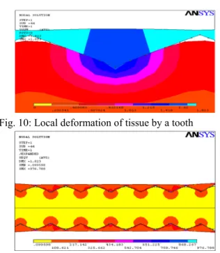
Fig. 9: Meshing and loading of semi-model Table 1: Time dependent shear modulus
t (sec) 0 1 2 3 4 5
G(t) Mpa
117.5 50.6 26.2 17.1 13.7 12.4
When the teeth of the grasper is indented into the tissue, deformation of the tissue, Von Mises stress, stresses in x, y (normal stresses) and y-x directions (shear stress) are obtained and shown in figures 10-14.
Fig. 10: Local deformation of tissue by a tooth
Fig. 11: Von Mises stress in tissue
Fig. 13: Normal stress in x-axis
Fig. 14: Shear stress in xy-axis
Following relations are employed to calculate pressure in the contact surfaces:
j i ij x t nn s
t x
p( , )= ( , ) (13)
where, ni or nj are the normals to the contact surfaces and sij are the values of stresses on the surface of the contact area. For the grasper with semi angles of 60°, normal to the surface is given as:
j i
n=−0.5 +0.866 , for the right side of teeth (14)
j i
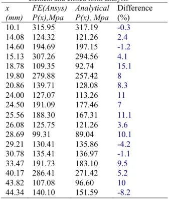
n=0.5 +0.866 , for the left side of teeth (15) Substituting the values of stresses resulting from FEA in equation (13), we can calculate the contact pressure. It has been found that a close agreement exists in the contact pressure obtained from FEM and that by closed form solution. In general, the FEA yielded higher values than those by closed form analysis except in a few isolated cases without any identifiable trends. The magnitudes of contact pressure under the same loading and situation of the analytical part are outlined in the table 2.
4. Experimental tests: Experimental tests have been
performed on two typical elastometric materials. These materials possess characteristics similar to these tissues. Piezoelectric polymer Polyvinylidene fluoride (PVDF) films have been used as the sensing elements on the grasper to obtain force and contact pressure.
Table 2: Comparison of contact pressures by finite element and closed form analysis* x
(mm)
FE(Ansys) P(x),Mpa
Analytical P(x), Mpa
Difference (%)
10.1 315.95 317.19 -0.3
14.08 124.32 121.26 2.4
14.60 194.69 197.15 -1.2
15.13 307.26 294.56 4.1
18.78 109.35 92.74 15.1
19.80 279.88 257.42 8
20.86 139.71 128.08 8.3
24.00 127.07 113.26 11
24.50 191.09 177.46 7
25.56 188.30 167.31 11.1
26.08 125.75 121.26 3.6
28.69 99.31 89.04 10.1
29.21 130.41 135.86 -4.2
30.78 135.41 136.97 -1.1
33.47 191.73 183.10 9.5
40.17 286.41 271.42 5.2
43.82 107.08 96.60 10
44.34 140.10 151.59 -8.2
*Initial and boundary conditions: a=2mm, t=0, G(0)=117.45 Mpa
Initially we designed, fabricated and calibrated an array of 25µ thick uniaxially drawn PVDF sensor. PVDF films are arranged to form parallel strips of sensing elements. Four strips of uniaxially drawn metalized on both sides of PVDF films are glued onto a prototype grasper (figure 15). In gluing of the PVDF films, care was taken to ensure that the strips of the films were glued uniformly with a thin layer of non-conductive glue. It is important to note that PVDF is more sensitive in the drawn direction. The piezoelectric coefficient in the drawn direction is ten time higher than that in the transverse directions. To this end, all the strips of the PVDF films were glued on the grasper in such a way that the drawn directions of the films were aligned towards the depth of the teeth. This would ensure that all of the sensing elements have the same sensitivity.
contact area. Therefore, the ratio of the voltages shows the ratio of the contact forces and pressures on the specified contact areas.
Fig. 15: Schematic of four strips of PVDF film glued on a single prototype tooth
Fig. 16: Block diagram of the experimental setup
Fig. 17: Experimental setup
The schematic diagram of the experimental measurement setup, developed to analyze the performance of the sensor, is shown in figure 16.The complete experimental set up with all the electronic
components and the display unit is shown in the figure 17.
Since the tooth of grasper is symmetrical about the line passing through the tip, only two voltage signals that are produced by sensing areas on one side of tooth are analyzed. Figure 18 show the four teeth macro type fabricated grasper. The purpose of the tests is to find the contact pressure ratio between the two areas on single side of a tooth for four teeth of the grasper.
Fig. 18: Macro type grasper and press unit
Figure 19 and 20 show the responses of the sensors under a step load-unloading for two different samples. The sensor outputs of Material 1 are shown in figure 19 which is harder than Material 2 whose output is shown in figure 20. Channels 1 to 4 are related to the sensors which are close to the tip of the teeth and channels 5 to 8 are connected to the sensors that are fixed in the lower sides of teeth. 50 Hz main frequency was superimposed on the transient signals. During the experimental analysis, this frequency was filtered.
contact force and pressure decrease which shows the effect of viscoelasticity of the materials.
Fig. 19: Sensor output under a step load for Material 1 (E = 32 Mpa)
Fig. 20: Sensor output under a step load for Material 2 (E=7 Mpa)
Table 3: The average force ratios obtained from ten times signal capturing between the sensing areas close to tip with the lower sensing areas
Experimental Closed
form
Finite Element Material
1
2.06 2.15 2.27
Material 2
1.93 2.17 2.21
CONCLUSION
The closed form analysis provides relations between total force, contact area, and relaxation and creep modulus for linear viscoelastic grasping contact with a corrugated wedge-like profile. Comparison of the results in finite element with closed form analysis shows that the assumption that the contact stresses are close to the contact area, is correct. Therefore we could use the superposition principle for the closed form grasping analysis. In addition, the finite element results agree with the results of the closed form analysis at different times during application of the load.
The study shows that under a constant load the contact area increases exponentially. Thus, fast unloading is essential for preventing any damage to tissues especially when the endurance pressure is applied to the tissues. On the other hand, the total force applied to the grasper decreases with time for a constant contact area. Another result of this study is that by increasing the number of the teeth, the rate of change of contact area reduces. In other words, to prevent any possible damage to the tissue, the number of the teeth must be increased. The experimental analysis is shown to support the closed form and FEA results.
REFERENCES
1. Dong, S.K. and Y.W. Ki, 1998. Microsurgical Telerobot System: Proc. of the IEEE/RSJ Int. Conf. on Intelligent Robotics and Systems, 945- 950.
2. Melzer, H.H., M.O. Schurr and W. Kunert, 1993. Intelligent Surgical Instrument System: Endoscop Surg Allied Techno,1: 165-170.
3. McGinty, J.B., S.S. Burkhart and R.W. Jackson, 2002. Operative Arthroscopy: Lippincott Williams & Wilkins Philadelphia.
4. Dargahi, J. and S. Najarian, 2004 Analysis of a Membrane Type Polymeric Based Tactile Sensor For Biomedical and Medical Robotic Applications: Sensors Material, 16: 25-41.
5. Dargahi, J., 2002. An Endoscopic and Robotic Tooth-like Compliance and Roughness Tactile Sensor: J. Mech. Design,124: 576-582.
6. Dario, P., D. De Rossi, C. Domenici and R. Francesconi, 1984. Ferroelectric Polymer Tactile Sensor With Anthropomorphic Features: Proc. IEEE Inter.Conf. on Robotics Atlanta GA, 332-340.
7. Gary, B.L. and R.S. Fearing, 1996, A Surface Micromachined Microtactile Sensor Array: Proc. of IEEE Int. Conf. on Robotics and Automation Minneapolis Minnesota, 1-6.
8. Fearing, R. S., G. Moy and E. Tan, 1997. Some Basic Issues in Teletaction: IEEE International Conference on Robotics and Automation: Albuquerque USA, 3093-3099
9. Sokhanvar, S., M. Packirisamy and J. Dargahi, 2007. A Multifunctional PVDF-Based Tactile Sensor For Minimally Invasive Surgery: Smart Mater. Struct. 16(4): 989-998.
11. Shikida, M., T. Shimizu, K. Sato and K. Itoigawa, 2003. Active Tactile Sensor For Detecting Contact Force and Hardness of an Object: Sensors and Actuators A., 103: 213-221.
12. Dargahi, J., 2004. A Three Sensing Element Piezoelectric Tactile Sensor For Robotic and Prosthetic Applications: Sensors Actuators A Phys., 80(1): 23-30.
13. Narayanan, N.B., A. Bonakdar, J. Dargahi, M. Packirisamy and R. Bhat, 2006 : Design and Analysis of a Micromachined Piezoelectric Sensor For Measuring Viscoelastic Properties of Tissues in Minimally Invasive Surgery: Smart Material and Structures, (15): 1684-1690
14. Read, W.H., 1950. Stress Analysis For Compressible Viscoelastic Materials: Journal of Applied Physics,21: 671-674.
15. Lee, E.H., 1955: Stress Analysis in Viscoelastic Bodies: Quarterly of Applied Mathematics, (13): 183-190.
16. Radok, J. R. M., 1957. Viscoelastic Stress Analysis: Quarterly of Applied Mathematics. 15: 198-202.
17. Lee, E. H. and J. R. M. Radok, 1960. The Contact Problem For Viscoelastic Bodies: Journal of Applied Mechanics. 27: 438-444. 18. Hunter, S. C., 1960. The Hertz Problem For a
Rigid Spherical Indenter and a Viscoelastic Half-space: Journal of the Mechanics and Physics of Solids, 8: 219-234
19. Graham, G. A. C., 1965. The Contact Problem in the Linear Theory of Viscoelasticity: International Journal of Engineering Science, 3: 27-46
20. Graham, G. A. C., 1967. The Contact Problem in the Linear Theory of Viscoelasticity When the Time Dependent Contact Area Has Any Number of Maxima and Minima: International Journal of Engineering Science, 5: 495-514
21. Ting, T. C. T., 1966. The Contact Stresses Between a Rigid Indenter and a Viscoelastic Half-Space: Journal of Applied Mechanics, 33: 845-854
22. Ting, T. C. T., 1968. Contact Problems in the Linear Theory of Viscoelasticity: Journal of Applied Mechanics, 35:248-254
23. Cheng L, X. Xia, W. Yu, L. E. Scriven and W. W. Gerberich, 2000. Flat Punch Indentation of Viscoelastic Material: Journal of Polymer Science: Polymer Physics 38: 10-22
24. Shimizu, S., M. Yanagimoto Yand Sakai, 1999. Pyramidal Indentation Load-Depth Curve of Viscoelastic Material: Journal of Materials Research, 14: 4075-4086.
25. Sakai, M., 2002. Time-Dependent Viscoelastic Relation Between Load and Penetration For an Axisymmteric Indenter: Philosophical Magazine A. 82: 1841-1849.
26. Oyen, M., L and R. F. Cook, 2003. Load-Displacement Behavior During Sharp Indentation of Viscous-Elastic-Plastic materials: Journal of Materials Research, 18: 139-150. 27. Bonakdar, A., J. Dargahi and R. Bhat 2006
Grasping Contact Analysis of Viscoelastic Materials With Applications in Minimally Invasive Surgery: Proc. of ASME Int. Mech. Eng. Congress and Exposition Chicago Illinois. 28. Bonakdar, A., M. Molavi, J. Dargahi, R. Bhat,
2007. Grasping Contact Analysis of Tissues With Semi-Cylindrical Teeth Grasper For Minimally Invasive Surgery Application: ASME Bioengineering Conference Keystone Colorado. 29. Mase, G. T. and G. E. Mase, 1999. Continuum
Mechanics for Engineers (2nd edn): CRC Boca Raton.