A R C H I V E S
O f
F O U N D R Y E N G I N E E R I N G
Published quarterly as the organ of the Foundry Commission of the Polish Academy of Sciences
ISSN (1897-3310) Volume 9 Issue 1/2009
65-68
15/1
Operating characteristics of turbine mixers
based on the analysis of power demand of
the mixer’s drive
A. Fedoryszyn a*, Cz. Rudyb
a
Wydziaá Odlewnictwa AGH, Reymonta Str. 23, 30-059 Kraków, Poland
b
PPP TECHNICAL, Zielonogórska 1A. Str, 67-100 Nowa Sól, Poland *Corresponding autor. E-mail address: [email protected]
Received: 26.02.2009; accepted in revised form: 30.03.2009
Abstract
Optimisation of the turbine mixer’s performance during the preparations of the sand mix still remains an important issue as this mixer type is now in widespread use. Monitoring techniques of the system sand mixing include the analysis of electric power demand by the mixer’s drive based on measurements of power components. This study shows the operating characteristics of turbine mixers as the function of electric power demand by the drive system.
Keywords: sand processing, rebonding of moulding sand, roller and turbine mixers
1. Power demand of roller mixer’s
drive
Mixing processes involve the blending of silica sand, bentonite, coal dust (or mixture) and water. The purpose of mixing is to homogenise the mixture and ensure that the rebonding agent should be uniformly distributed over the grains. This unit was designed for separating casts from the runner system. the number of casts in a batch ranges from 1 to 4 on the given level, there are 1-48 of them on 1-12 levels. The mass of the batch varies from 5 to 12 kg.
Mechanical mixing is an energy-consuming process since grain displacements due to the motions of the mixer’s working parts are accompanied by friction and other reaction forces. Roller mixers are widely used for preparing
synthetic system sand with bentonite. This is so when the sand mix is made from fresh components. In roller mixers the rebonding agent is distributed during the repeated cycles of compaction and loosening, while the acting forces must be greater than cohesion. For that reason kneading and spreading operations are performed by the roller systems, involving rolling and slipping
.
Power demand of a mixing system in a roller mixer is shown in Fig 1. During the mixing cycle the power demand increases with an increase in the surface area of grains covered with clay-water slurry, accompanied by an increase in the sand mix resistance. The mixing cycle involves: I- idle run, II- charging of mix components; III- homogenisation; IV- water dosing; V- mixing of wet mix, VI- emptying the mixer.
2. Operating characteristics of turbine
mixers
Rebonding of sand mix is a common practice in foundry engineering. The sand mix contains used sand whose grains are already coated with the rebonding material. Rebonding of the used sand [3,4] involves disintegration of grain agglomerates and uniform distribution of the rebodning agent in the entire volume of the sand mix batch, coating of sand grains with the rebonding agent and activation of thus formed coating. Turbine (rotor) mixers are now in widespread use as they feature high efficiency and short mixing cycles.
Fig 1. Power demand of the roller mixer’s drive system [2]
The characteristic of power demand by the mixer’s drive is based on the current intensity patterns. In the case of electric-powered devices, current intensity is a key parameter quoted alongside their power ratings.
The control object was a turbine mixer MTP-500, with the capacity of 500 kg in one charge, the mixer pan being inclined at Į=30o. Measurements were taken during the tests aimed to select the rotors with the optimal blade design in terms of their range and inclination angle [3]. Removable rotors were used in which the inclination angle of the screw line was Ȗ=8o and the screw line was inclined in either of the two directions: left- and right-handed rotors. Blade inclination angles were ȕ=10o, 15o, 30o. The experimental facility included:
a continuous –control unit to regulate the rotor rpm (i.e. a frequency converter AMD-F0150/RN53A with the nominal power ratings 75 kW,
the device for measuring the loading of the rotor’s drive’s motor- a PLC controller GE FANUC complete with the IC693ALG221 module,
software tools: PROFICY MACHINE EDITION v5.6 for graphic recording of the motor loading
Process parameters are summarised in Table 1 and the motor loading variations are shown in Figs 2÷4.
Castings are sectioned manually, by swinging movements of the displacement lever in the vertical (Fig 2). The holder of an abrasive wheel is capable of horizontal displacement, so the castings can be sectioned on both sides of the main gate.
Table 1. Operating parameters of a mixer MTP-500 with the tested rotor units [3]
Rotor type A B C
Mixing time tm, s 170 90 170
Rotor rpm nw,1/min 571 571 571
Milled blades ß,0 15* 15* 10*
Sand mix moisture,
predetermined wk,% 5 5 5
Used sand moisture wp,% 2,24 2,31 2,31
Temperature of used
sand Tp,0C 15,5 15,4 13,7
Water dose mw,l 14,3 13,9 13,7
Idle current intensity I0,A 14,5 14,4 14,5
Maximal current
intensity Imax,A 52,0 49,2 67,0
* left-handed rotor ** right-handed rotor
Duration times of particular stages involved in the mixing process are indicated on the graphs. Water was dosed at the rate 1 m3/s and the water dosing stage was over after 33 seconds from the beginning of the cycle. It appears that several patterns can be followed to reach the maximum current level, corresponding to the predetermined degree of the grain coating with the rebonding agent. The time required to reach the maximum current level Imax was: t=85.3 s (A), t=74.4s (B) and t=112.1 s (C) respectively, for the cycle times being: tc=170
s (A), tc=90s (B) and tc=170s (C). The mixing time (from
the instant the water dosing was over to reaching the maximum current level) was: tm=52.1 s (A), tm= 54.4 s(B),
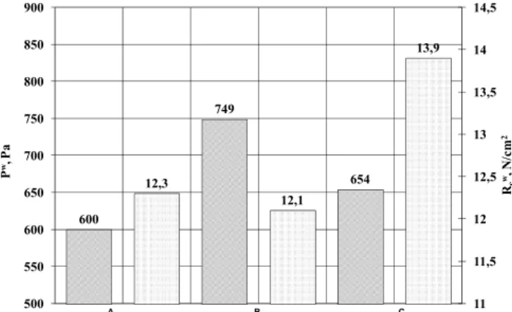
tm= 75.0 s(C). Measurements of the current intensity of the
driving system were taken alongside the standard tests of process parameters of the sand mix [3]: permeability Pw, compression strength Rcw and compactibility. The results
are compiled in Fig 5.
Fig 2. Power consumption by a mixer drive A, in a turbine mixer [3]
Fig 3. Power consumption by a mixer drive B, in a turbine mixer [3]
Fig 4. Power consumption by a mixer drive C, in a turbine mixer [3]
600 749 654 12,3 12,1 13,9 11 11,5 12 12,5 13 13,5 14 14,5 500 550 600 650 700 750 800 850 900 Rc
w, N
/c
m
2
P
w, P
a
A B C
Fig 5. Process parameters of system sand rebonded in a turbine mixer MTP-500
The average sand mix compactibility was: Z=51.1 %(A), Z=50.2% (B) and Z= 52.5% (C).
Comparison of the operating characteristics of the mixers and process parameters of the sand mix suggests that the rebonding time of 90s was fully sufficient. It was found out that the rotor design B and its operating parameters (direction and rpm) appeared most favourable.
4. Conclusions
Power demand of the mixer’s drive reveals the mixer’s operating characteristics and reliable monitoring of the mixing processes involving the evaluation of power consumption affords us the means to select the optimal process parameters and to maximise the efficiency of sand mix preparation.
Current intensity is the key parameter governing the power consumption by the driving unit. Variations of current intensity best illustrate the sand preparation processes. The recorded current levels yield the
characteristics of the mixing unit, supported by monitoring and control schemes.
Recording of current levels allows for effective monitoring of the sand mix preparation processes and for optimising the solutions of the mixing systems, which is corroborated by the present study, providing an evaluation of the rotor’s performance depending on the blade design.
Acknowledgements
This paper is supported through the AGH-UST research grants no 10.10.170.315.
References
[1] BodzoĔ L., DaĔko J., ĩurawski L.: Podstawy teorii maszyn
odlewniczych. Maszyny do przygotowywania materiaáów i
mas formierskich. Fundamentals of Foundry Machines Theory. Machines for Preparation of Moulding Sands and Moulding Materials. Skrypt AGH nr 919. Kraków, 1984. [in Polish]
[2] Gorskij A.I.: Rasczet maszin i mechanizmow awtomaticzeskichlinij litejnogo proizwodstwa. Calculations for machines and mechanisms of automatic process lines in foundries Maszinostrojenie. Moskwa, 1978
[3] Rudy Cz.: Rozprawa doktorska - Manuskrypt. Doctoral
dissertation – manuscript. Wydziaá Odlewnictwa AGH.
Kraków, 2008
[4] Smyksy K., Wrona R., Zióákowski E.: Monitoring of power
demand of foundry machinery, using the example of paddle mixers. Archives of Foundry Engineering. Nr.1., Vol. 8, 2008, p. 177
[5] Sztefko F.: Analiza mocy napĊdu krąĪników w mieszarkach
typu Simpson. Analysis of rollers’ drive power in Simpson mixers. Zeszyty Naukowe AGH. Metalurgia i Odlewnictwo, z.125, nr. 1271, Kraków 1989, s. 245
[6] Smyksy K., Zióákowski E., Wrona R.: Selected aspects
involved In operations of monitoring system for moulding sand preparation process. Archives of Foundry Engineering. Vol. 8, issue 2, 2008, p. 183
![Table 1. Operating parameters of a mixer MTP-500 with the tested rotor units [3]](https://thumb-eu.123doks.com/thumbv2/123dok_br/18321211.349806/2.954.100.428.430.647/table-operating-parameters-mixer-mtp-tested-rotor-units.webp)
![Fig 2. Power consumption by a mixer drive A, in a turbine mixer [3]](https://thumb-eu.123doks.com/thumbv2/123dok_br/18321211.349806/3.954.201.777.169.463/fig-power-consumption-mixer-drive-turbine-mixer.webp)