Vol-7, Special Issue-Number2-April, 2016, pp1245-1251 http://www.bipublication.com
Research Article
High frequency ballast algorithm simulation base on
square error optimize on MATLAB
Hassan Moslemi
''Engineering and Technical College Department,
Esfarayen University of Technology, North Khorasan, Esfarayen, Iran" H.moslemi@esfarayen.ac.ir
ABSTRACT
In this paper we study Design of the High pressure electronic ballast algorithm for sodium vapor lamp in MATLAB that regulate power by variable frequency despite of voltage variations and characteristic lamp gnawing in total time of lamp longevity. Electronic ballast structure and algorithm of design it, is explained and its design with mathematic model is described. Design process using offer plan in such that in addition of dominant to voice resonance variable frequency and voltage variations keep lamp power to nominal power. Design process performed by consideration characteristic of 250 W sodium vapor lamp. Theory studies ratification with MATLAB.
Keywords: resonance inverter, sodium vapor, trapezoid diagram, ballast structure, high variable frequency
1. INTRODUCTION
Electronic ballasts have an noticeable advantage into magnetic ballast, include of higher power factor and efficiency, lower THD, stability of output power in spite of voltage variations, melting of lamp electrode less accomplish therefore lamp longevity be longer, But Electronic ballasts is consumed lower because of higher cost. Electronic ballast include of high frequency and low frequency ballasts. low frequency ballast(under 400 HZ), using square current wave[1], due to instantaneous power of wave form is steady can prevent of voice resonance[2].but basic problem is difficult manufacture and high primary cost. Today high pressure sodium vapor lamp due to long longevity and higher optic gain using for population light widely. But for junction and light this lamps need to (a middle element) ballast, which due to negative impedance characteristic using for limit lamp current. High frequency electronic ballast have higher efficiency and longevity, lower volume and weigh [3]. voice resonances appearance and increment of steady pressure waves in plasma,
design, in (4) section survey simulation result.High frequency with variable frequency ballast algorithm design coming in (5) and finally show ratification of this algorithm by simulation in (6), and review most results in (7).
2. Important parameter of high pressure sodium vapor lamp
In time, voltage and number of pulse in one period be in allowable limit is very important. Starting time of lamp is consider as important element that depend to lamp power, starting time of lamp should not operate sooner than ballast because of lamp longevity decrement. Also starting current attain to 1.5 nominal current. Most of sodium vapor lamp needing to ignition circuit that provide high voltage for lamp starting. Over than allowable limit pulse
decrease lamp longevity, starter pulse have
about 3.5~5.5 kV voltage and 1 µs time. Lamp
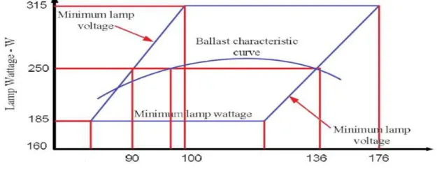
starting time is an important element that depend to lamp power. Most important element in ballast design is trapezoid diagram, that in fig. 1, 250 W sodium vapor lamp trapezoid diagram base on C78,42 ANSI standard and EN60662 is showing[4,5]. That showing power variationfrom minimum to maximum when lamp voltage from new lamp varied to old lamp. Lamp voltage in effect of blacking vacation pipe and decrement of sodium, for each 2000 hour work increase about 4~8 V [4]. That for 250 W lamp in nominal power lamp voltage varied from 100 to 175 V. This variation due to gnawing effect on lamp power clearly. Offer electronic ballast in this paper delivered regulated power to lamp in total lamp longevity.
Fig. 1:250 W sodium vapor lamp trapezoid diagram
Value of allowable CF for current is the other sodium vapor lamp effective parameter in ballast design; that is equal to ratio of maximum current to effective current. Allowable CF base on standard for sodium vapor lamp is 2.2. Increment over than this value cause to decrease lamp longevity. Longevity and less light characteristic are other element. Base on IESNA standard lamp longevity are hours that half of one major group of one kind of lamp will be demolish, i.e. lampoptic fluxwill less than %1 from nominal optic flux. Studies show longevity of vapor sodium lamp is 36000 hours and optic flux of them in end of lamp longevity about %85 of start longevity's that by proper electronic ballast design must compensate lamp
power in end of longevity’s till optic flux in end and start of longevity is equal. Variation limit of frequency is another important element for sodium vapor lamp that work by high frequency, with tent to kind of 250 W sodium vapor lamp, if this variation limit of frequency be under 45 KHz could prevent of voice resonance (AR) in this type of lamp.
2-1. electronic ballast structure
with consideration to effect current, input current peak, input instantaneous current and input voltage peak. But most important section is power factor compensate (PFC) and inverter section. The other section is lateralballast inverter in a ballast output. Fire circuit that used for lamp ignition not consider in ballast design because of it is not effect on steady state
behavior and ballast efficiency. PFC section is an additive converter that receivedrectified voltage of net and delivered the DC voltage (constant Vb) to inverter in output. As well PFC
keeping power factor near one. True operate of PFC section is very effective in quality of ballast elements.
Fig. 2: Electronic ballast structure
3. Important element in ballast design
Design is based on lamp input power; then lamp power variation amplitude and elements that effect on lamp power for design and offer algorithm for simulation must have been detected. Design method has been selected based on 250 W sodium vapor lamp, because wide using of this lamp in population light. For optimize ballast characteristic, operating and standard parameter is considered.
3-1. switching frequency
Voice resonance is main problem of high frequency electronic ballast. If switching frequency be over than 30 KHz and lower than 45 KHz, with tent to used distinct sodium vapor lamp kind could prevent from voice resonance. Therefore using (30-45) KHz frequency limit in ballast design. We can waver from switching lost in off time in Electronic ballast showing in fig. 2, Therefore it is not discussed in select maximum frequency because operate in voltage zero in ON time in switching. As high frequency decrease ballast volume and value, if voice resonance and lamp characteristic allow we can increase variation frequency limit.
3-2. resonance inverter voltage
PFC section that showing in fig. 2, is anadditive converter that have a higher output voltage into
input voltage. PFC could not have correct operate when PFC input voltage near to output voltage [6, 7]. In possible limit in optimum design Vbconsider small for decrease cost.
Select %85 to %110 range of nominal voltage cause to proficiency and reliability, which is in ballast design Vb=400 V is considered and
Vb(max)=400 V, because of Vb(max) increment over
than limit cause to increase using capacitor and mosfets cost and have higher lost[1].
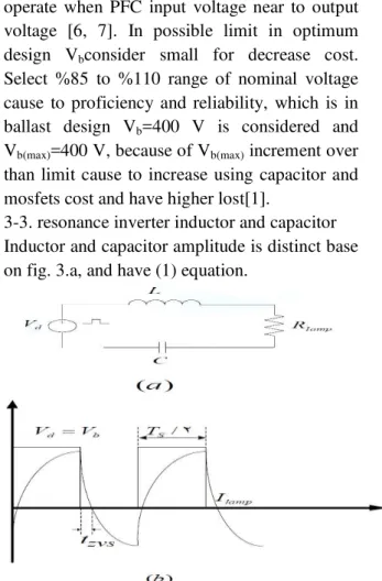
3-3. resonance inverter inductor and capacitor Inductor and capacitor amplitude is distinct base on fig. 3.a, and have (1) equation.
(1)
(2)
From fig. 4, can see that for constant K value of decreased when WsCRLAMP increased, in
the other hand with big capacitor we needing to smaller inductor, therefore inductor and capacitor have nearly relationship.WsCRLAMP
Must bebigger than 4; butWsCRLAMP increment
over than 40 not effect on inductor and only cause to cost increment. Capacitor variation amplitude must be selected in bellow limit because of select sodium vapor lamp power and inverter frequency.
(3) With notice to (3) when fs(35~45)KHz ,
RLAMP(min)=32.4 Ω, RLAMP(max)=97.3, Capacitor
variation amplitude for 250 W sodium vapor lamp electronic ballast is 0.082≤ C ≤ 4.75µF therefore standard capacitor that used in this limit is :
C { 0.082 0.1 0.15 0.22 0.27 0.33 0.39 0.47 0.56 0.68 0.82 1.0 1.5 2.2 3.3 4.7 }
µF (4)
Self-variationamplitude describe as:
(5)
(6)
Using (5), (6) when fs(35~45)KHz ,
RLAMP(min)=32.4 Ω, PLAMP=50, RLAMP(max)=97.3 Ω, Vb(max)=400 V, Vb(min)=360 V, therefore
inductor variation amplitude is 41≤ L≤1114 µH for sodium vapor lamp electronic ballast[1]. In fig. 4, showing WsL/RLAMP into WsCRLAMPfor
variant value of K. For K=0 surface under diagram distinctoperation point that switching zero voltage in time of ON is not achieved. ThenWsCRLAMP is such selected that resonance
happen distance from under k=0 diagram surface.
Fig. 4: WsL/RLAMP into WsCRLAMPvariation 3-4. lamp power
Keeping lamp power near to nominal power cause to optic flux is be steady and lamp longevity is increased as base on standard lamp power over than 1.45 nominal power cause to decrease in lamp longevity and if power be lower than 0.5 of nominal cause to undesirable output light.
3-5. lamp resistance
Minimum and maximum of lamp resistance is 42.2, 98.4 respectively. As showing in fig. 1, minimum and maximum lamp voltage in 250 W nominal power is 100 and 175 respectively for sodium vapor lamp. Sodium vapor lamp in high frequency showing resistance model.
4. Survey Input lamp power methods
ballast is design based on input lamp power, therefore lamp power achieved from steady state model; fig 3.a, showing equivalent circuit of electronic ballast equilibrium state, that Vd is
inverter input voltage and L,C is resonance element and RLAMP is sodium vapor lamp. Input
lamp power is achieved from 2 method include of time domain (TD) and frequency domain (FD) analysis.
4-1. Time domain analysis (TD)
PLAMP = RLAMPI2LAMP(rms)
(7)
ILAMP(rms) is lamp effective current that be
achieved from equation that show mathematic inverter model. In half wave inverter Vb(t)
generated voltage source achieved from (8), [8, 9].
(8)
4-2. frequency domain analysis (FD)
Fig. 3.b, showing lamp current and inverter input voltage steady state waves, lateral resonance inverter has two work state, top switch is OFF and bottom switch is ON then input voltage to inverter is zero top switch is ON and bottom switch is OFF then input voltage to inverter is Vb.
Vbis an inverter voltage, Ws=2πFs, Fs is
switchingfrequency, C and L are resonance inductor and capacitor respectively [5]. By using sinus approximation for lamp current, delivery power to lamp is:
(9)
Base on (9), Vb, fS, L, C, RLAMP are effective
parameter into lamp input power that described later.
5. Offer Electronic ballast algorithm
By using offer algorithmVb, fS, L, C and RLAMP
are detected that delivery power to lamp is depend to them.
Lamp power have minimum variation into nominal power by optimum value of parameter, therefore lamp gnawing effect has minimum variant on nominal power. Lamp power is function of lamp resistance when this parameter is optimum and constant. Number of effective elements in design is decrease and only Vb, L,
RLAMP is remaining by select standard capacitor
and frequency variation limit. In next stage
optimum value for L, Vbis selected by minimum
square error optimize. Lamp power will have minimum error into nominal power in time of lamp longevity because lamp power Plamp (Ri)
achieved by high accuracy in TD [1].
(10)
Ri is lamp resistance and R0 = Rlamp (min),
Rn=Rlamp (max), it is important that tent to Ri is a
parameter with high variation in lamp longevity time. In bellow one method for achieved optimum Ri is mentioned because of select Ri is
very important and effective on select optimum value. Let us assume that per 2000 hours' work we have 3 V increment in lamp voltage, lamp resistance from (11) is calculated.
(11)
That 0 ≤ I ≤ (Vlapm(max)- Vlapm(min))/3 and
Vlapm(max) and Vlapm(min) is maximum and
minimum of lamp voltage in nominal power respectively.
With tent to trapezoid diagram in fig. 1, for 250 W sodium vapor lamp Vlapm (max) =175 v and
Vlapm (min) =100 v. In this state time parameter in
optimize is considered and nominal power very near to nominal value of itself in lamp longevity time. Weshould tent to bellow qualification for optimize art characteristic in algorithmdesign [1].
Zero voltage second in time of ON must be guaranty for increased reliability and decrease switching lost. Therefore (tzvs) zero voltage second showing in fig. 3.a, must be over 1µs in
lamp longevity time. Lamp current CF moreover 2.2 for sodium vapor lamp, significant decreased lamp longevity.
total lamp longevity and near to nominal power. Table 1, showing algorithm simulation results.
Table 1: optimum value achieved from electronic ballast of variation frequency sodium vapor lamp
(SE)1/2 C (µF) LOPT(µH)
62.5 0.082 639
62.9 0.1 581
63.7 0.15 581
64.4 0.22 439
64.8 0.27 417
65.2 0.33 400
65.5 0.39 388
65.8 0.47 377
65.9 0.56 368
66.2 0.68 360
66.5 0.82 353
66.7 1.0 347
66.9 1.5 339
67.1 2.2 334
67.2 3.3 331
67.2 4.7 328
Table 1, showing possible chooses base on suggested algorithm.Column 2 is standard capacitor can show process for 250 W sodium vapor lamp electronic ballast. Column 3 showing optimized value of inductors. Biggercapacitor cause to inductor be small base on table 1, column 1 showing square root of error indicator base on (12). Lower (SE)1/2 have minimum lamp gnawing effect on nominal power.
(12)
Base on table 1, (SE)1/2 is steady for every select and not effect on select optimum design. Therefore with notice to inductor and capacitor costs and negative relationship between this two parameter using of bellow value for electronic ballast design:
LOPT = 334 µH COPT = 2.2 µF
(13)
6. Survey design from simulation
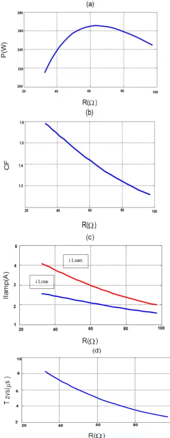
In this section operation of 250 W sodium vapor lamp electronic ballast design base on simulation with MATLAB performed. Simulation is based on optimized values. Base on (5-3) section 250 W sodium vapor lamp resistance variation amplitude is 32.4 ≤ R ≤ 97.3 fig 5.a, showing delivery power to lamp into lamp resistance. Lamp power is about 250 W regulated on 32.4 ≤ R ≤ 97.3. Then delivery power to lamp is near to nominal power in total lamp longevity. Fig. 5.b, showing current lamp
CF in lamp longevity time. Fig. 5.c, showing lamp current in lamp longevity time, that blue curve showing lamp effective current and red curve showing lamp current peak. Lamp current using for inductor design and select inverter switches.
Fig. 5.d, showing tzvs in total lamp longevity
time.tzvsas show bigger than 1µF. Then
tzvscondition in start achieved.
7. CONCLUSIONS
In this paper high frequency electronic ballast for 250 W sodium vapor lamp with variation frequency is described. Electronic ballast design algorithm base on optimize minimum square error achieved design parameter. Designed electronic ballast have intrinsic regulation power capability. And keep power delivery to lamp near to nominal power. If frequency be constant with lamp gnawing because of lamp resistance variation it is possible that voice resonance is happens. But if in limit frequency be variant could by change to frequency achieve to stable area distance from voice resonance. MATLAB’s result showing that designed ballast has good performance in total time lamp longevity.
8. REFERENCES
1. M. A. D. Costa, T. B. Marchesan, J. S. da Silveira, A. R. Seidel. R. N. do Prado, J. M. A. Alvarez, “Integrated Power Topologies to Supply HPS lamps: A Comparative Study,”IEEE Trans. On Power Electronics, Vol. 25, No. 8, 2010
2. Chhun, L.; Maussion, P.; Bhosle, S.; Zissis, G.; Durrieu, O.;”Injection of adjacent frequency signals for acoustic resonance avoidance in HPS lamp”, Industrial Electronics, 2009. IECON '09. 35th Annual Conference of IEEE, 2009, pp: 3537-3544. 3. Chin, S.M.; Sheng, Y.T.; Ching, R.L.; Jia, H.;
“Investigation into High-Frequency Operating Characteristics of Metal-Halide Lamps.” Plasma Science, IEEE Transactions, on Volume: 37, 2009, pp: 2234 – 2240. 4.IEC, “High-Pressure sodium Vapor lamps,”
European Standard N60662, June 1990. 5. NEMA, “ANSI C78.42 2004 for Electric
lamps, High Pressure sodium lamps,” American National Standard Lighting Group, 2004.
6 .G, R. Sincero, A. J. Perin, “High Pressure Sodium Lamp High Power Factor Electronic Ballasts Using AC-AC Converters,” IEEE
Trans. Power Electron.Vol. 22, No. 3, pp. 804-814, 2007.
7. Hiralal M. Suryawanshi, Vijay B. Borghate. Manojkumar R. Ramteke, Krishna L. Thakre, “ electronic Ballast Using a Symmetrical Half-Bridge Inverter Operating at Unity-Power factor and High Efficiency.” Journal of Power Electronics, Vol. 3, No. 3, pp. 175-184, 2003.
8. L. R. Nerone, “A mathematical model the class D converter for compact fluorescent ballasts,” IEEE Trans. On Power Electronics, Vol. 10, No. 6, pp.708-715, 1995.