A New Method of Reference Signal Generation Applied To
UPQC-PHEV For Grid Integration of WECS-SCIG
Girish B M
*, Prof. Anguraja R
***(PG Scholar, Dept of EEE, DBIT, VTU, Bengaluru. E-mail: [email protected])
** (Associate Professor, Dept of EEE, DBIT, VTU, Bengaluru.
E-mail: [email protected]
)ABSTRACT
In this paper a new reference signal generation control technique is proposed for integration of Unified Power Quality Conditioner (UPQC) with Plug-in Hybrid Electric Vehicle (PHEV) for overcoming voltage sag and other voltage fault conditions on wind farms which is connected to grid. The interaction of wind generators and grid causes increased short circuit current which leads to instability during fault conditions. The new control technique which generate reference signals for series active power filter (Series APF) and shunt active power filter (Shunt APF) of UPQC by using PHEV as an Energy Storage System (ESS) which will take care of all types of voltage faults occurred in the system and provide energy storage to DC link between Series APF and Shunt APF parts of UPQC. The control scheme proposed also maintains transaction of active and reactive power of Wind Energy Conversion System based on Squirrel Cage Induction Generators (WECS-SCIG) and grid. The fuzzy logic provides fast and dynamic response to clear faults occurred in the system.
Keywords:
UPQC; Reference signals generation; PHEV; Voltage Sag; Fuzzy Logic Controller; GridIntegration.
I.
INTRODUCTION
In the last few years, large-scale integration of wind energy has become a fact due to social and geopolitical concerns [1]. As the penetration of large scale wind turbines into the electric power grid increases, connection codes are requiring turbines ride through a short-term low or zero voltage event at the point of common coupling (PCC) [2]. In electrical terms, the evolution from short-circuit induction generators and wound rotor induction generators with super synchronous cascade has reached its end with the introduction of doubly fed induction generators (DFIGs, or doubly fed asynchronous generators) with bidirectional and partially rated power inverters[2]. Many wind turbines are connected in weak areas where heavy unsymmetrical loads, unsymmetrical transformer windings, or Transmission impedance and transient faults (voltage dip) will be typical sources of unbalanced operation mode. In this condition DFIG may lead to loss of control due to high power demands for inverters. Presently, variable speed wind turbine generator system (WTGS) is becoming more popular than that of fixed speed Induction generators. The fixed speed wind generator due to their superior characteristics such as brushless and rugged construction, low cost, maintenance free, and operational simplicity, but they require large reactive power to recover the air gap flux when a short circuit fault occurs in the power system [3] unless otherwise the induction generator becomes unstable due to the large difference between electromagnetic and
mechanical torques, and then it requires to be disconnected from the power system. A shutdown of large wind farm may have a serious effect on the power system operation. Voltage sag and other voltage disturbances will decrease the electrical torque of Squirrel-Cage Induction Generators (SCIG); consequently, the active power of Wind Energy Conversion System based SCIG (WECS-SCIG) will be reduced [4].Whereas, the mismatch between mechanical and electrical power make increasing the speed of rotor of SCIG. By increasing of rotor speed, the wind farm absorb more reactive power that can cause more depression in voltage magnitude. After clearing the fault, if the rotor speed does not over its critical speed, SCIG can get the equilibrium point. Otherwise, if the wind generators unable to withstand against faults, it must be disconnected from the grid and it may cause a cascading voltage collapse and the breakdown of the rest of wind farm generators [14].
In order to overcome above mentioned problems, normal operation wind turbine is necessary, for that new grid integration codes are passed, which will improve stability of WECS-SCIG under fault conditions occurring in the power system
II.
MODEL
OF
THE
PROPOSED
SYSTEM
The power generated by wind turbine PW
and speed ratio is given in below equations
) , ( v 2
1 3
p
W S C
P (1)
v R /
(2)
Where ρ is air density, S is the swept area, Ω is the
rotor speed, v is the wind speed, and Cp is the power
coefficient, λ is the speed ratio and β is the pitch
angle.
Fig 1 shows the wind farm based SCIG connected to the grid with UPQC-PHEV
Fig 1 The configuration of proposed system with UPQC-PHEV
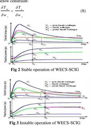
A. Effects of voltage sag or voltage faults on SCIG In fig 2 which shows electrical torrque-slip and reactive power-slip charactersistics of Squirrel Caged Induction Generator(SCIG) under voltage sag on stable condition. During this at point A1, when V1
decrese to V2, slip incresed to S2 until fault clear at
C1. During fault time, the generator draws more
resactive power by increasinng of slip speed and it may cause the voltage of generator not to restore even after the fault is cleared. The voltage of generator can be restored by find of equilibrium point at A1. Fig 3 shows instability condition. For
obtaining constraint and margin stabiliity of SCIG;
dt dw J T
Tm e r (3)
Where Tm and Te are mechanical torque and
electrical torque respectively. Also wr is angular
velocity of rotor. On solving
dt w d J T
Tm e ( r)
(4)
For small changes, the torque-slip curve can be taken as straight lines thus;
r r m m w w T
T
& r
r e
e w
w T
T
(5)
Substituting eq. (5) in eq. (4) we get:
dt w d J w w T w T r r r e r
m ( )
(6)
By solving differential eq. (6) resultant eq. (7)
k e w w r e r m w T w T J
r
] ) [( 1 0 (7)
Where k and w0 are constant parameters and
obtained initial conditions.
Hence, stability equilibrium point should have the below constraint: r e r m w T w T
(8)
Fig 2 Stable operation of WECS-SCIG
Fig 3 Instable operation of WECS-SCIG
From fig 2 and fig 3 the margin point of stability of WECS-SCIG is the pull-out point of electrical torque. If the fault continued in so that electriccal torque reach over the pull-out point , SCIG will become insatble and may lead to complete system collapse and it have to be disconnected from grid [5].
On other hand, from fig 2 when the fault is cleared, Point of Common Coupling (PCC) voltage will return to equillbrium point. Since the rotor slip is not able to change instaneously due to mechanical momentum inertia, a larger amount of reactive power is absorbed by SCIG and slope of electrical
torque-speed curve
r w e T will be greater than slope
of mechanical torque-speed curve r w Tm
. By this
Fig 4 Voltage magnitude of wind farm without UPQC
Fig 5 shows the rotor speed of SCIG without UPQC. In this when the fault is cleared at t=1 sec, rotor speed increase extensively and thus wind generator should be disconnected from the grid.
Fig 5 Rotor speed of SCIG without UPQC
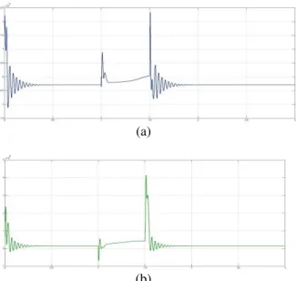
Fig 6 shows active power (p) and reactive power (q) are shown seperately. Increse in reactive power cause the magnitude of voltage to collapse and when the fault is cleared at t=1 sec, active power generated by wind farm will be zero.
Thus considering Spanish grid code integration requirements, the wind farm performances can be improved and will make better results under low voltage or fault events
(a)
(b)
Fig 6 (a) Active power and (b) Reactive power of SCIG without UPQC
III.
CONTROL STRATEGY OF UPQC
The conventional control strategy of UPQC are based on PI controller. In this control strategy Series APF and Shunt APF are parts of UPQC which are used to overcome voltage sag issues [6-9]. The series APF control/regulate the bus voltage through stored energy from PHEV voltage in DC link through Shunt part. The Shunt APF controls the voltage DC-link by using PHEV and control of the reactive power via control of current.
A. Series part of Control Strategy
The effective control strategy for Series APF is UPQC-P and UPQC-Q for voltage sag compensation [7-9]. This control is based on Unit Vector Templates from the distorted supply. The series APF is such that it injects voltages (VCa, VCb,
VCc), which cancel out distortions and unbalance
present in the supply voltage. (VSa, VSb, VSc) thus
making the voltages at the load terminal (VLa, VLb,
VLc) perfectly balanced and sinusoidal with the
desired amplitude. Thus the sum of supply voltage and the injected series APF voltage makes the desired voltage at load terminals. The control strategy for series APF is shown in Fig 7. Since the supply voltage is unbalanced or distorted, a Phase Locked Loop (PLL) is used to achieve synchronization with the supply. To generate injected voltage, supply voltage signals are compared with the reference signals and these signals are then given to hysteresis controller along with the sensed series APF output voltages. The hysteresis controller generates the switching signals such that the voltage at the load becomes the desired sinusoidal output voltage. The injected voltage across the series transformer through the ripple filter cancels out the harmonics and unbalance present in the supply voltage.
B.Shunt part of Control Strategy
The instantaneous reactive power (p-q) theory is used to generate reference signal for shunt APF. The control block diagram is shown in Fig 8. The instantaneous three phase voltages and currents
are transformed to α-β-0 coordinates as shown in Equation (9) and (10)
(9)
(10)
Equation (11) shows calculation of instantaneous real power (p), imaginary power (q), and zero sequence power (p0) components drawn by the load
(11)
where (12) Where, the ˜ sign points to the alternating
term and ̅sign points to the direct component of each
active and reactive power. In general, each one of the active and reactive instantaneous power contains a direct component and an alternating component. The direct component of each represents the power of the fundamentals of current and voltage. The alternating term is the power of the harmonics of currents and voltages.
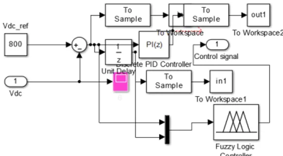
DC-link voltage regulator is designed to give both good compensation and an excellent transient response. The actual DC-link capacitor voltage is compared by a reference value and the error is processed in a proportional-integral (PI) controller, which is employed for the voltage control loop since it acts in order to minimize the steady-state error of the DC-link voltage to zero.[12]
Fig 8 Control scheme of shunt APF
IV.
PHEV MODEL FOR UPQC
A Plug in Hybrid Electric Vehicle is a one that uses rechargeable batteries, or another energy storage device , that can be recharged by plugging it
in to an external source of electric vehicle. PHEV’s
give a way to design its bi-drectional charger as UPQC converters.PHEV’s provide a way for storing of electric wind energy and solar photovoltaic energy at times of excess generation and use it as an ubiquitious power grid whenever needs for improvement of power stability and quality of those resoucres[10]
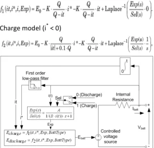
To develop an appropriate model for PHEV, a dynamic and versatile model of rechargeable battery has chosen where the elements of battery are variable, as they depend on electrolyte temperature as well as State Of Charge (SOC) [15]. Fig 10 shows a sample model of Nickel-Metal Hydride battery (Ni-MH). Compared to other battery chemistries, the primary advantage of Ni-MH is its life cycle and overall history of safety.
Discharge model (i*> 0)
Charge model (i* < 0)
Fig 9 Equivalent circuit of battery
ti t dt
Q SOC
0 ( ) 1 1 100
Where,
Ebatt = Nonlinear voltage in V
E0 = Constant voltage in V
Exp(s) = Exponential zone dynamics in V Sel(s) = represents the battery mode 0 during battery discharge 1 during battery charging
K = Polarization constant (Ah-1) or Polarization resistance (Ohm)
i* = Low frequency current dynamics (A) i = Battery current (A)
Q = Maximum battery capacity (Ah) A = Exponential voltage (V) B = Exponential capacity (Ah)-1
The Exp(s) transfer function represents the hysteresis phenomenon for the Lead-Acid, Ni-CD and Ni-MH batteries during charge and discharge cycles [16]. The exponential voltage increases when battery is charging, no matter the SOC of the battery. When the battery is discharging, the exponential voltage decreases immediately
Fig 10 A sample model of Ni-MH battery
In this it is 200V, 6.5Ah Ni-MH (Nickel Metal Hydride) battery connected to a constant load of 50A. The DC machine is connected in parallel with the load and operates at no load torque. When the State Of Charge (SOC) of the battery goes under 0.4 (40%), a negative load torque of 200 Nm is applied to the machine so it acts as generator to recharge the battery. When the SOC goes over 80%. The load torque is removed so only the battery supplies the 50amps load. The battery is discharged by the constant DC load of 50A. When the SOC drops under 0.4 a mechanical torque of -200 Nm is applied so the machine acts as generator and provides a current of 100A. Hence, 50A goes to load and 50A goes to recharge the battery. When the SOC goes over 0.8, the mechanical torque is removed and the machine operates freely and then cycle restarts.
Similarly for varying voltage fluctuations in WECS-SCIG and grid connected system it will provide necessary power required and absorb excessive power during varying conditions of the system [15].
By using PHEV the energy for injection into Shunt APF part is accessible and there is no shortage of energy under deep voltage sag.
V.
UPQC-PHEV BASED ON FUZZY
LOGIC CONTROLLER (FLC)
Recently, Fuzzy Logic Controllers (FLC) have gained great deal of interest in various applications and have been applied in the power electronics and FACTS devices. The advantages of FLC over the classic PI controller are that they do not require an accurate mathematical model; they can work with
imprecise inputs, can handle nonlinearity and robust than classic controller. [11]
The configuration of fuzzy controller consists of attractive features such as simplicity, fast dynamic response, and automation, while using a low cost hardware and software implementation.
FLC are formed by simple rule based on “If x and y then z”. These rules are defined by taking help from person’s experience and knowledge about
the system behavior. The performance is improved by the correct combinations of these rules. Each of the rules defines one membership which is the function of FLC. More sensitivity is provided in the control mechanism of FLC by increasing the number of membership functions.
In the present model a two input and one output FLC is taken which is shown in Fig 11. The input signals for the FLC are the DC-link voltage variations in the shunt APF that obtained from active powers of series APF, shunt APF and PHEV. Also the deviations in the PCC voltage are the inputs signals for FLC in the series APF.
Fig 11 FLC used in the present model
It consists of fuzzification part, fuzzy inference part, and defuzzification/constant outputs. The numeric input-variable measurements are transformed by fuzzification part into fuzzy linguistic variable, which is clearly defined boundary with a crisp. The inference part consists of membership functions and rule bases which are obtained from an understanding of the UPQC-PHEV behavior and using of system procedure. These are modified and tuned by system performance. A triangular membership function has the advantages of simplicity and easier implementation and is chosen for the present model. In the defuzzification process, the controller outputs represented as linguistic variables by a fuzzy set are converted to the real control signals.
and control the magnitude of the injected voltage based on these rules. Table 1 shows 49 linguistic rules which will directly process three phase supply voltages to improve response time of UPQC-PHEV. Table 1 The rule table of FLC
VI.
SIMULATION RESULTS
Fig 12 to fig 16 shows the comparison of UPQC-PI controller and UPQC-PHEV-FLC. The figure shows that fuzzy logic provide fast and dynamic response for the fault occurred in the wind farm which improve transient stability and life cycle of wind farm.
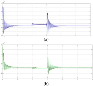
Fig 12 shows comparison of rotor speed variation during fault occurred between 1 to 1.5 sec. In this rising time of UPQC-PHEV-FLC is very small than that of UPQC-PHEV and thus oscillation of speed of rotor at fault time is very low.
Fig 12 Comparison of rotor speed of SCIG without UPQC, UPQC with PI controller,
UPQC-PHEV-FLC
(a)
(b)
Fig 13 Active (a) and Reactive Power (b) of SCIG without UPQC
(a)
(b)
Fig 14 Active (a) and Reactive Power (b) of SCIG with UPQC
Fig 13 and Fig 14 shows the active power (p) and reactive power (q) of SCIG by using without UPQC and UPQC-PHEV-FLC respectively
(b)
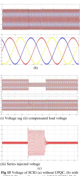
(i) Voltage sag (ii) compensated load voltage
(iii) Series injected voltage (c)
Fig 15 Voltage of SCIG (a) without UPQC, (b) with UPQC-PI controller, (c) with UPQC-PHEV-FLC
Fig 15 shows the voltage magnitude and voltage angle phase of SCIG (a) shows deep voltage sag between 1 to 1.5 sec without UPQC compensation (b) voltage sag occurred during this is compensated with UPQC and conventional PI controller (c) in this when voltage sag occurs between 1to 1.5 sec and series APF will provide necessary compensation which is shown in fig. For to do necessary compensation the reference signals have been by FLC and thus UPQC-PHEV-FLC provides compensation in very fast and dynamic way so that stability of the system is maintained and also power quality and other voltage disturbances are compensated.
Fig 16 DC-link voltage variation by using PHEV
VII.
CONCLUSION
In this paper a Unified Power Quality Conditioner (UPQC) has been investigated for power quality enhancement and voltage faults/disturbances which occur in wind farm (WECS-SCIG) connected to grid. UPQC is an hybrid filter and it is combination of Series APF and Shunt APF which is used to compensate voltage disturbances and current distortion respectively. The real and reactive power compensation is provided by UPQC-PHEV. This control is achieved by generation of new reference signals which are generated by Fuzzy Logic Controller (FLC). The voltage sag occurs]in time interval between 1 to 1.5 sec which is compensated by Series APF part of UPQC. FLC will provide fast and dynamic response whenever fault occurs in system. Thus proposed system UPQC-PHEV-FLC improves power quality and voltage disturbances issues in grid connected WECS-SCIG and also compensation of active and reactive power.
REFERENCES
[1]. The European Wind Energy Association, EWEA Publications, 2005.[Online]. Available: http://www. ewea. org/.
[2]. S. M.Muyeen, R. Takahashi, T. Murata, and 1. Tamura, "A variable speed wind turbine control strategy to meet wind farm grid code requirements, " IEEE Trans. Power Syst. , vol. 25, no. 1, pp. 331-340, Feb. 2010.
[3]. S. K. Salman, and AL. J. Teo, "Windmill modelling consideration and factors influencing the stability of a grid-connected wind power based embedded generator", IEEE Trans. Power Syst. , vol. 18, no. 2, pp. 793- 802, 2003.
[4]. P. S. Flannery and G. Venkataramanan, "A fault tolerant doubly fed induction generator wind turbine using a parallel grid side rectifier and series grid side converter, " IEEE Trans. on Power Electronics, vol. 23, no. 3, pp. 1126 - 1135, May 2008. [5]. Lie Xu, Senior Member, IEEE, Liangzhong
[6]. M. Molinas, 1. A Suul, and T. Undeland, " Low Voltage Ride Through of Wind Farms With Cage Generators: ST ATCOM Versus SVC", IEEE Trans. on Power Elec. , vol. 23, no. 3, pp 1104-1117, May 2008. [7]. A E. Leon, M. F. Farias, P. E. Battaiotto,
"Control Strategy of a DVR to Improve Stability in Wind Farms Using Squirrel-Cage Induction Generators", IEEE Trans. on Power Sys. , vol. 26, no. 3, pp. 1609-1617, Aug. 2011. 241
[8]. N.G. Jayanti M Basu M.F. Conlon K. Gaughan, "Rating requirements of the unified power quality conditioner to integrate the fixed speed induction generator-type wind generation to the grid" IET Renew. Power Gener. , Vol. 3, Iss. 2, pp. 133-143, 2009.
[9]. M.F. Farias, P. E. Battaiotto, M. G. Cendoya, "Investigation of UPQC for Sag Compensation in Wind Farms to Weak Grid Connections" , Journal of Electrical Engineering: Theory and Application, Vol .1, no. 3, pp.174-181, 2011.
[10]. M. Basu, S.P. D as, G. K D ubey. 'Comparative evaluation of two models of UPQC for suitable interface to enhance power quality', Electr. Power Syst. Res. , vol. 77, no. 7, pp. 821-830, 2007.
[11]. T.1.Ross,"FuzzyLogic with Engineering Applications", John Wiley & Sons Ltd, 2004.
[12]. V. Khadkikar and A Chandra, "A New Control Philosophy for Unified Power Quality Conditioner (UPQC) to Co-ordinate Load Reactive Power Demand Between Shunt and Series Inverters". IEEE Trans. On Power Delivery, vol. 23, no. 4, p. 2522-2534, 2008.
[13]. M. H. 1. Bollen, "Understanding Power Quality Problems-Voltage Sags and Interuptions", IEEE Press, 2000.
[14]. P. Kundur, Power system stability and control, McGraw-Hill Inc., 1994.
[15]. M. Aryanezhad, M. Joorabian and E. Ostadaghaee, "Modeling and Simulation of PHEV as a Virtual UPQC Based on Vehicle to Grid Technology", International Review on Modelling and Simulations (I.RE. MO.S.), vol. 5, no. 4, Aug. 2012 [16]. H. G. Zhang, X. B. Li, W. G. Qian,
"Modeling and Simulation of the Ni-Mh Battery", Advanced Materials Research, Vols. 602-604, pp. 1040-1043, 2013
AUTHORS
Girish B M- Received B.E in Electrical and Electronics Engineering from University BDT college of Engineering, Davanagere in 2014
He is currently pursuing M.Tech in Power System Engineering from Don Bosco Institute of Technoloy. Here research includes power system, renewable energy.
Anguraja R- Received B.E in Electrical and Electronics Engineering from Bharathidasan University, Tirunchirapalli and M.Tech in High Voltage Engineering from SASTRA university, Thanjavur and currently pursuing Ph.D in High Voltage Engineering from Jain University.