ISSN 1941-7020
© 2009 Science Publications
Corresponding Author: Zulkarnain Lubis,Faculty of Electrical and Automation Engineering Technology, TATi University College, Malaysia
Mathematical Modeling of the Three Phase Induction Motor Couple to DC
Motor in Hybrid Electric Vehicle
1,2
Zulkarnain Lubis,
2A.N. Abdalla,
2Mortaza and
1,2Ruzlaini Ghon
1
Faculty of Electrical and Automation Engineering Technology,
TATi University College, Malaysia
2
Faculty of Electrical and Electronic Engineering, University Malaysia Pahang,
Kuantan, Malaysia
Abstract:Problem statement: With emphasis on a cleaner environment and efficient operation, vehicles today rely more and more heavily on electrical power generation for success. Approach: Mathematical modeling the components of the HEV as the three phase induction motor couple to DC motor in hybrid electric vehicle was introduced. The controller of Induction Motor (IM) was designed based on input-output feedback linearization technique. It allowed greater electrical generation capacity and the fuel economy and emissions benefits of hybrid electric automotive propulsion. Results: A typical series hybrid electric vehicle was modeled and investigated. Conclusion: Various tests, such as acceleration traversing ramp and fuel consumption and emission were performed on the proposed model of 3 phase induction motor coupler DC motor in electric hybrid vehicles drive.
Key words: Hybrid electrical vehicle, induction motor, DC machine
INTRODUCTION
With the oil price shocks of the past few decades, as well as an increasing awareness of the emissions of air pollutants and greenhouse gases from cars and trucks, the interest to investigate alternative vehicle propulsion systems has grown. This challenge of fuel economy standards is promoting optimized and sometimes novel vehicle power-train architectures, which combine the traditional Internal Combustion Engine (ICE) with various forms of electric drives. The different types of the Hybrid Electric Vehicles (HEV) are real competitors of the classical ICE driven cars.
In an all-Electric Vehicle (EV) there is no ICE, but all other components exist including batteries with excessive power. EVs and HEVs are studied by numerous authors in the past, one comprehensive study is that of Chan[1]. First full-scale hybrid vehicle work in Turkey is Doblo/Tofas example realized at Marmara Research Centre[2]. There have been university theses and an industry project constitutes the basics of this study[3-7]. One of the main contribution is that of Gokce[4], energy conservation and energy balance method is adopted. The input-output feedback linearization technique combined with an adaptive backstopping observer in stator reference frame the induction motor[5] using in series hybrid electric vehicle is controlled[8].
This study focus on a new HEV modeling to make a couple two electric motor IM and DCM close loop sinusoidal PWM inverter to control the speed of a three phase induction motor. This compact inverter had its hardware reduced to a minimum through the use of a Programmable Integrated Circuit (PIC) micro-controller (PIC16C73A). In this sense a microcomputer interface was avoided. At the end, a typical HEV is modeled and investigated. Simulation results obtained show the IM and other components performances for a typical city drive cycle.
MATERIALS AND METHODS
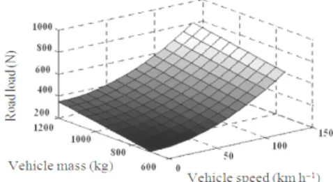
The performance of an electric vehicle: The first step in vehicle performance modeling is to write an equation for the electric force. This is the force transmitted to the ground through the drive wheels and propelling the vehicle forward. This force must overcome the road load and accelerate the vehicle as shown in Fig. 1.
The rolling resistance is primarily due to the friction of the vehicle tires on the road and can be written as:
froll = fr Mg (1)
Where:
M = The vehicle mass
Fig. 1: Basic of forces on a vehicle
The aerodynamic drag is due to the friction of the body of vehicle moving through the air. The formula for this component is as in the following. Dynamic modeling and simulation of an induction motor with:
fAD = 1
2 ξ CD AV 2
(2)
The gravity force due to the slope of the road can be expressed by:
fgrade = Mg. sin α (3)
where, α is the grade angle.
In addition to the forces shown in Fig. 3, another one is needed to provide the linear acceleration of the vehicle given by:
facc = Mα = M dv
dt (4)
The propulsion system must now overcome the road loads and accelerate the vehicle by the tractive force, Ftot , as follows:
Ftot = froll + fAD + fgarde + facc (5)
A typical road load characteristic as a function of the speed and mass of a vehicle is shown in Fig. 2. Wheels and axels convert Ftot and the speed of vehicle to torque and angular speed requirements for differential as follows:
Twhell = Ftot rwheel, ωwheel = V/ rwheel (6) where, Twhell , rwheel and ωwheel are the tractive torque, the radius and the angular velocity at the wheels, respectively.
The angular torque velocity and torque of the wheels are converted to motor rpm and motor torque requirements using the gears ratio at differential and gearbox as follows:
ωm = Gfd Ggb ωwheel, Tm = Twhell/Gfd Ggb (7)
where, Gfd and Ggb are respectively differential and gear box gears ratios.
Fig. 2: Summary of forces on a vehicle
Fig. 3: Power assembly diagram of HEV
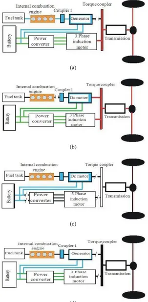
Proposed method: A Hybrid Electrical Vehicle (HEV) may consist of an Internal Combustion Engine (ICE), Electric Motor (EM), Electric Generator (EG), power electronic circuits, advanced Electronic Control Units (ECU), a complex mechanical transmission and a battery bank.
Figure 3 shows the structure of drive assembly of a hybrid electric car (There are electrical machines, generator and starter (M/G), starter and the main Motor (M)). G/M is an Integrated Started and Generator (ISG) which connects with the Internal Combustion Engine (ICE) using a couple. The starter is a standby one. The M, which is subject of this study, is called main motor. It connects with the wheels through the final gear. Main motor is a three phase asynchronous Motor. The battery pack is a 288 V, 10 Ah NiH one (Fig. 3).
(a)
(b)
(c)
(d)
Fig. 4: Operation of 3 phase induction motor coupler DC motor in electric hybrid vehicles drive. (a): Car run normal condition; (b): Car run in hybrid electric; (c): Car standby (OFF); (d): Starting 3 phase induction motor
RESULTS
First the system is simulated for DCM+IM test cycle. Due to the electric motor has been modeled dynamically in SIMULINK. The data for IM and EV is in the appendix. Figure 5 shows the simulation block diagram. The drive cycle gives the required vehicle speed then the torque and speed requested from the electric motor. The current drawn from IM power supply shows the battery performance.
Fig. 5: Block diagram of hybrid electric induction motor
Fig. 6: Simulation block diagram
The dynamic behavior of the IM in the DCM+IM drive cycle is shown in Fig. 4a and b. Figure 4a shows Power assembly diagram of HEV Normal Condition the ECE drive cycle. Figure 4c and d show the IM torque and average torque, power assembly diagram of HEV in Hybrid Electric.
Results is explained by the pact that, in experimental test were observed a strong influence of motor inductance in coupler to DC motor, more precisely, in the power system, however in the simulation such influence was not considered and also non-linearity and additional losses. Figure7 shows optimal torque in hybrid electric vehicle with Thee phase Induction motor coupled with DC motor TIM+DCM. Figure 8 shows results comparison-couple the Three phase Induction Motor and DC Motor.
DISCUSSION
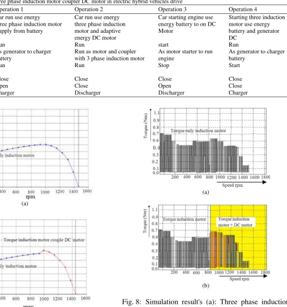
Table 1: Operation of three phase induction motor coupler DC motor in electric hybrid vehicles drive
Equipment Operation 1 Operation 2 Operation 3 Operation 4
Car run use energy Car run use energy Car starting engine use Starting three induction
three phase induction motor three phase induction energy battery to on DC motor use energy
Supply from battery motor and adaptive Motor battery and generator
energy DC motor DC
Engine Run Run start Run
DC machine As generator to charger Run as motor and coupler As motor starter to run As generator to charger
battery with 3 phase induction motor engine battery
Three phase Run Run Stop Start
Induction motor
Coupler 1 Close Close Close Close
Torque coupler 2 Open Close Open Close
Battery Charger Discharger Discharger Charger
(a)
(b)
Fig. 7: Experimental torque of (a): Thee phase induction motor; (b): Thee phase induction motor coupled with DC motor TIM+DCM
In the regenerative brake mode shown in Fig. 4d, the M/G and the main motor work in generator mode to charge the battery. These will decrease the fuel consumption.
The three-phase induction motor speed control was couple to DC motor in close loop schematic, as shown Fig. 5 and 8 Torque data was acquired through a Hall Effect sensor, with a torque relation speed for each 0.1 Nm shown in scale we have 1500 rpm as resulting speed.
(a)
(b)
Fig. 8: Simulation result's (a): Three phase induction motor Tmax IM = 0.7 M Nm−1 (b): Couple three phase induction motor and DC motor TIM+DCM
CONCLUSION
tools have been developed for the design and analysis of electric and hybrid electric vehicles. Simulation results have also been shown the IM and IM+DCM, maximum torque in graph Fig. 7 and 8.
ACKNOWLEDGEMENT
The researchers thank the Faculty of Electrical and Electronic Engineering, of WHO that funded the project with resources received for research from university Malaysia Pahang.
REFERENCES
1. Chan, C.C., 2002. The state of art of electric and hybrid vehicles. Proc. IEEE, 90: 247-275. http://cat.inist.fr/?aModele=afficheN&cpsidt=1355 4416
2. Chen, K., A. Bouscayrol, A. Berthon, P. Delarue, D. Hissel and R. Trigui, 2008. Global modeling of different vehicles using energetic macroscopic representation. Proceedings of the Vehicle Power and Propulsion Conference, Sept. 3-5, IEEE Xplore
Press, Harbin, pp: 1-7. DOI:
10.1109/VPPC.2008.4677728
3. Gao, D.W., C. Mi and A. Emadi, 2006. Modeling and simulation of electric and hybrid vehicles.
Proc. IEEE, 95: 729-745. DOI:
10.1109/JPROC.2006.890127
4. Yimin G., S.E. Gay, M. Ehsani, R.F. Thelen and R.E. Hebner, 2003. Flywheel electric motor/generator characterization for hybrid vehicles. Proceedings of the IEEE 58th Vehicular Technology Conference, VTC 2003-Fall, Oct. 6-9, IEEE Xplore Press, USA., pp: 3321-3325. DOI: 10.1109/VETECF.1286291
5. Singh, B. and J. Ravi, 2006. Modified direct torque control of matrix converter fed induction motor drive power electronics, drives and energy systems. Proceedings of the International Conference on Pedes, Dec. 12-15, IEEE Xplore Press, USA., pp: 1-7. DOI: 10.1109/PEDES.2006.344383 6. Yuan Z. and Xu Longya, 2006. Application of dual
mechanical port machine in hybrid electrical vehicles. Proceedings of the Vehicle Power and Propulsion Conference, Sept. 6-8, IEEE Xplore
Press, Windsor, pp: 1-5. DOI:
10.1109/VPPC.2006.364304
7. Kuo, K.S., L.J. Shang, H.Z. Chen and K.W. Jwo, 2004. Flux compensated direct torque control of induction motor drives for low speed operation power electronics. IEEE Trans., 19: 1608-1613. DOI: 10.1109/TPEL.2004.836618